HAL Id: hal-02149149
https://hal-upec-upem.archives-ouvertes.fr/hal-02149149
Submitted on 6 Jun 2019
HAL is a multi-disciplinary open access
archive for the deposit and dissemination of sci-entific research documents, whether they are pub-lished or not. The documents may come from teaching and research institutions in France or abroad, or from public or private research centers.
L’archive ouverte pluridisciplinaire HAL, est destinée au dépôt et à la diffusion de documents scientifiques de niveau recherche, publiés ou non, émanant des établissements d’enseignement et de recherche français ou étrangers, des laboratoires publics ou privés.
Ferrero
To cite this version:
Jean-Emmanuel Chambe, Olivier Dorival, Christophe Bouvet, Jean-François Ferrero. Crushing of composite tubular structures and energy absorption for aircraft seat development. 18th European Conference on Composite Materials, Jun 2018, Athènes, Greece. �hal-02149149�
Jean-Emmanuel Chambe, Olivier Dorival, Christophe Bouvet, Jean-François Ferrero
Jean-Emmanuel Chambe , Olivier Dorival , Christophe Bouvet, Jean-François Ferrero
1
Université de Toulouse, Institut Clément Ader, UMR CNRS 5312, INSA/UPS/ISAE-SUPAERO/Mines Albi,
3 rue Caroline Aigle, F-31400 Toulouse, France
Email: jean-emmanuel.chambe@isae-supaero.fr, www.institut-clement-ader.org/ pageperso.php?id=jechambe
Email: christophe.bouvet@isae-supaero.fr, www.institut-clement-ader.org/pageperso.php?id=cbouvet Email: jean-francois.ferrero@univ-tlse3.fr, www.institut-clement-ader.org/pageperso.php?id=jfferrero
2
ICAM Site de Toulouse, 75 avenue de Grande-Bretagne, CS 97615, F-31076 Toulouse Cedex 3 Email: olivier.dorival@icam.fr, www.institut-clement-ader.org/pageperso.php?id=odorival
Keywords: Crushing, Composite tubes, Energy dissipation, Specific Energy Absorption, Aeronautics
Abstract
The purpose of this study is to evaluate and compare the ability of diverse composite structures to dissipate the energy generated during a crash. To this end, composite tubes were tested in compression in order to identify their behavior and determine their absorbing capabilities using the Specific Energy Absorption (SEA) (energy absorbed per unit weight). Various composite tubular structures with different materials and architectures were tested, including hybrid composition of carbon-aramid and hybrid configuration of 0/90 UD with woven or braided fabric. Several inventive and experimental trigger systems have been tested to try and enhance the absorption capabilities of the tested structures. SEA values up to 140 kJ.kg-1 were obtained, achieving better than most instances from the literature, reaching around 80 kJ.kg-1. Specimens with 0°-oriented fibers coincidental with the direction of compression reached the highest SEA values while those with no fiber oriented in this direction performed poorly. Compression tests were also monitored by means of thermal imaging cameras in order to compare and evaluate the energy dissipated into thermal effects. Although an increase in temperature was clearly noted, the data spectrum was overall insufficient to lead to the SEA value.
1. Introduction
Two main failure mechanisms for composite tubular structures have been identified as either catastrophic or progressive failure [1, 2]. (Figure 1). For the latter failure mode, a distinction can be made as the composite tube may undergo progressive folding or progressive crushing [3]. (Figure 1). During the first case, composite tube walls progressively fold under successive local buckling (similar to shell buckling) when loaded in axial compression. The extremity of the tube yields in buckle mode, leading to hinge formation and progressive folding; the folded zone then grows progressively down the tube wall. For the second case, the tube collapses as a result of successive brittle fractures. The extremity of the tube breaks leading to the splaying of the tube wall and fragmentation. Local fracture occurs at the crush front; splaying and micro-fractures then propagate down the tube [3]. Such rupture tends to generate random sized debris.
In progressive crushing mode, damage mechanisms may be summed up into three types: (i) splaying, (ii) fragmentation and (iii) debris creation and accumulation [4]. (Figure 2).
Jean-Emmanuel Chambe, Olivier Dorival, Christophe Bouvet, Jean-François Ferrero
Figure 1. Catastrophic (a) and progressive (b) failure [2], progressive folding (c) and crushing (d) [3].
Figure 2. Main features and major damage mechanisms occurring at the crush zone (adaptedfrom[3]).
Fragmentation might occur at two levels: under the tip of the plies (due to micro-buckling of fibers for 0° plies and to multiple shear micro-cracks for 90° plies) or within the plies as intra-laminar failure, fiber breakage and matrix cracks (due to a combination of compression, bending and shear) [4]. (Figure 2). The localized fragmentation at the tip of the plies is pointed as the mechanism leading to the definition of the ply Mean Crushing Stress (MCS) [4].
Recent studies focus on Mean Crushing Stress (MCS) characterization [5, 4] on standalone plies and within laminates as well as the influence of fibers orientation, or braided structure [6–10] and mix or hybrid materials [11].
One means to characterize and compare the absorbing capability of materials is through the Specific Energy Absorption (SEA). The SEA value is given by the following equation (Eq.1):
(1)
where EA is the energy absorbed in J (given by the area under the force-displacement curve), divided by the mass of the crushed mater. F is the crushing load in N, s the crushing distance in m, is the density of the material in kg.m-3 and V the crushed volume of material in m3.
It can be established that the SEA value can be very closely approximated as an instant value using the crushing stress in MPa divided by the density of the crushed material.
Jean-Emmanuel Chambe, Olivier Dorival, Christophe Bouvet, Jean-François Ferrero
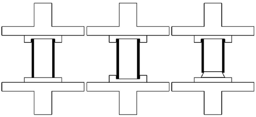
were tested for crushing initiation and hopeful enhancement. Tubular structures were clamped and encased at one end, while several options were tested for the other. For instance, they were (a) let free on a plane surface, (b) also encased, (c) positioned on a conic plug initiator. Figure 3 presents these three configurations.
Figure 3. Experimental set-ups with one end free (a), encased (b) and on a conic plug initiator (c).
2.2. Specimens and materials
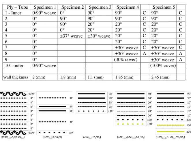
Five specimens with different structure and of different composition were tested in various crushing modes. Structural and material basis for the specimens include 12K HR carbon fibers and polymer Epoxy resin. Fibers orientation and laminate stratification differ from one specimen to another as shown in Figures 4 and 5 and summarized in Table 1. Provided tubular structures were machined and shaped in tubes of 100 mm length as pictured in Figure 4. Outer diameter was set at an average of 50 mm, with inner diameter varying from one sample to another due to stratification differences. Stratification layout and tube wall thickness are summarized in Table 1 for each sample.
Jean-Emmanuel Chambe, Olivier Dorival, Christophe Bouvet, Jean-François Ferrero
A duplicate set of specimens with identical dimensions was prepared; tubes in this set were filled to a fifth of their height with Epoxy resin, in the hope to achieve inner stabilization and therefore reach higher crushing stress values. In addition, this helps control which end will the crushing initiate from.
Table 1. Tube specimen stratification.
Ply – Tube Specimen 1 Specimen 2 Specimen 3 Specimen 4 Specimen 5
1 - Inner 0/90° weave 0° 90° 90° C 90° C 2 0° 90° 90° 90° C 90° C 3 0° 90° 20° 20° C 20° C 4 0° 0° 20° 20° C 20° C 5 0° 37° weave 30° weave 20° C 20° C 6 0° 20° C 20° C 7 0° 30° weave C 30° weave C 8 0° 30° weave A 30° weave A 9 0° (30% cover) 30° weave A
10 - outer 0/90° weave (100% cover)
Wall thickness 2 (mm) 1.8 (mm) 1.1 (mm) 1.85 (mm) 2.45 (mm)
Figure 5. Schematic representation of the five tube specimens by their stratification.
2.3. Experimental results
2.3.1 Visual observations and behavior
Although some specimens underwent catastrophic failure, breaking down from a midpoint zone of their wall length and not from their extremity, none underwent progressive folding, the majority following a progressive crushing scheme. Nevertheless, a clear difference was observed in the spreading array of damaged wall parts depending on the tests configurations (cf. Figure 3).
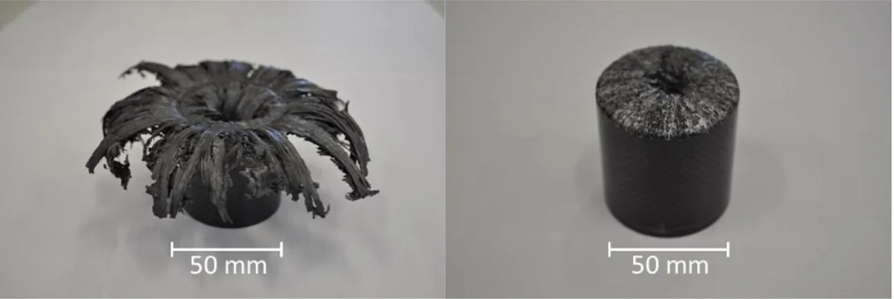
As an example, the pictures in Figure 6 present the difference in crushing behavior for the same CFRP tube specimen submitted to axial crushing under the first two different configurations presented in Figure 3. Both underwent progressive crushing. The first (left) corresponding to configuration type (a) presents inner and outer spreading of splayed parts, whereas the second (right) corresponding to configuration (b), have the whole bundle of splayed parts that folds towards the inside of the tube. Configuration type (c), with a cone-shaped plug initiator, does not differ much from configuration type (a) apart from the fact that the entire splayed bundle spreads on the outside.
Jean-Emmanuel Chambe, Olivier Dorival, Christophe Bouvet, Jean-François Ferrero
Figure 6. Crushed CFRP tubes showing outer spreading (left) and inner folding (right).
Figure 7 highlights major occurring damage resulting from progressive crushing instigated by quasi-static axial compression load for specimen 1 through the means of tomographic imaging for two different crushing modes ((a) and (b) when referring to Figure 3). Inner (a, b) and outer (b) splaying of fragmented or un-fragmented parts are clearly visible, as well as debris accumulation.
The crushing plane surface is schematized by a discontinued line on both pictures on Figure 7. It is strongly suspected that for each tube samples, folded plies at the end of the tube walls between the sane part of the tubes and the crushing surface moved back downward when the crushing force was unloaded, due to a spring back effect. Hence an estimated positioning of the crushing surface appearing to be situated within the tube and entering inside the tube structure.
Figure 7. Tomographic images of crushed CFRP tubes showing major damage for two configurations.
For the first configuration, a pyramidal-shaped debris accumulation can be observed at the center under the tube wall, between the tube section and the crushing surface, where the laminate plies spread towards the inside or the outside of the tubular structure. This debris accumulation forms from the void created by the plies splaying from the center under the tube wall then subsequently helps further and heighten this splaying.
Jean-Emmanuel Chambe, Olivier Dorival, Christophe Bouvet, Jean-François Ferrero
At the contact surface between the tube circular section and the plane surface, micro-bucking occurs progressively and successively, resulting in matrix and/or fibers fragmentation for the laminate plies that undergo such splaying. This damage increases the debris formation. As observed and mentioned in previous study, the formation and the evacuation or accumulation of debris remains rather random. For the second test configuration, damage mechanisms are similar in type and classification, but are all shifted toward the inside of the tube, since the outer wall is encased, leaving no leeway for splayed plies to spread that way. Incidentally, although major occurring damage are the same, their origin varies somewhat. Bending and folding resulting from the compression generate the splaying of the composite plies, and therefore the fracture and fragmentation for those sustaining a higher stress. Fragmentation still generates an important number of debris that varies in forms and shape, but those are freely evacuated from the crushing zone under the tube section to the inside of the tube. They do not form a tip that parts the laminate wall and split it, as observed with the pyramidal debris accumulation on the first configuration.
At the extremity of the tube wall, where the folding appears, outer plies seem to be more submitted to bending whereas inner plies undergo plain compression and break through intra-laminar fracture.
2.3.1 Specific Energy Absorption
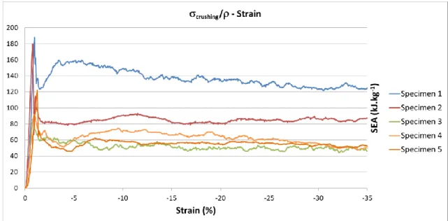
The Specific Energy Absorption was calculated after each crushing test for each specimen for every configuration. Results are presented in Figure 8, which highlights the benefit of specimen 1 in terms of energy absorption with a SEA value well above the others, at around 140 kJ.kg-1, and the good performance of specimen 2, with a SEA value of around 80 kJ.kg-1. It can be seen that specimens 3, 4 and 5 have a similar behavior and identical energy absorbing capability, but lesser than the others.
Figure 8. SEA evolution for 5 CFRP tube specimens submitted to pure axial crushing.
Similarity in behavior and energy absorbing capability for specimen 3, 4 and 5 are not incoherent when referring to Table 1 which shows the same basis structure for these specimens. Outer aramid covering does not improve or worsen the general behavior or energy absorbing capability.
Jean-Emmanuel Chambe, Olivier Dorival, Christophe Bouvet, Jean-François Ferrero
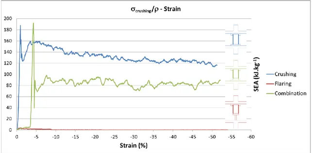
Figure 9. SEA evolution for 3 crushing configurations for the same CFRP tube specimen (n°1).
For each axial compression tests, a stiff peak can be observed on the load-displacement curves or the stress/density-strain curves as showed on Figure 8, when the structure yields before it starts collapsing by progressive crushing at a stable and constant load, as reflected by the continuous plateau level. Ideally the gap between the peak and plateau value has to be reduced to a minimum, as a small gap and constant plateau level means an optimized dissipation of energy for a fixed and given load value. The use of a conic plug initiator to introduce a radial flaring of the tube structure before it is submitted to crushing does not improve the energy absorbing capability, compared to pure and plain crushing, as it is shown in Figure 9. Moreover, this configuration worsens the energy absorbing capability at it significantly lowers the SEA value. At last, the use of the conic plug alone, passing through the tube along its whole length, hardly dissipate any energy.
Finally, no difference in crushing stress value was observed between specimens filled with Epoxy resin and plain hollow tubes.
Jean-Emmanuel Chambe, Olivier Dorival, Christophe Bouvet, Jean-François Ferrero
3. Conclusions
SEA values up to 140 kJ.kg-1 were obtained, achieving better than most instances from the literature, averaging around 30 kJ.kg-1 and reaching up to around 80 kJ.kg-1. (Figure 10).
Specimens with 0°-oriented fibers achieved better in energy absorption than specimens with none. Woven reinforcement on the inner and outer wall structure proved more effective than solid strengthening support such as poured resin in providing and achieving stability of the structure. Furthermore it helps containing 0°-oriented fibers from splaying and flaring too easily.
However, the additional aramid draping was proven needless in term of energy absorbing capacity. Yet this overlapping covering may be valuable in acting as a nest to refrain outer spreading by directing splayed chunks towards the inside and keep brittle parts within the inside of the tubular structure, avoiding expelled debris, as could be required in an aeronautical context.
Acknowledgments
The authors gratefully acknowledge the support of the Region Occitanie in the undertaking and establishment of this project.
References
[1] P.H. Thornton. Energy Absorption in Composite Structures, Journal of Composite Materials, 13(3):247–262, 1979.
[2] P.H. Thornton. The Crush of Fiber-Reinforced Plastics. In: N.P. Cheremisinoff, Ed., Handbook of
Ceramics and Composites Volume 1: Synthesis and Properties, Marcel Dekker Inc., New York,
307–337, 1990.
[3] D. Hull. A Unified Approach to Progressive Crushing of Fibre-Reinforced Composite Tubes.
Composites Science and Technology, 40(4):377–421, 1991.
[4] H.A. Israr, S. Rivallant, C. Bouvet, and J.J. Barrau. Finite element simulation of 0°/90° CFRP laminated plates subjected to crushing using a free-face-crushing concept, Composites Part A:
Applied Science and Manufacturing, 62:16–25, 2014.
[5] H.A. Israr, S. Rivallant, and J.J. Barrau. Experimental investigation on mean crushing stress characterization of carbon–epoxy plies under compressive crushing mode, Composite Structures, 96:357–364, 2013.
[6] X. Xiao, M.E. Botkin, and N.L. Johnson. Axial crush simulation of braided carbon tubes using MAT58 in LS-DYNA, Thin-Walled Structures, 47(6–7):740–749, 2009.
[7] X. Xiao, C.J. McGregor, R. Vaziri, and A. Poursartip. Progress in braided composite tube crush simulation, International Journal of Impact Engineering, 36(5):711–719, 2009.
[8] J.-S. Kim, H.-J. Yoon, and K.-B. Shin. A study on crushing behaviors of composite circular tubes with different reinforcing fibers, International Journal of Impact Engineering, 38(4):198–207, 2011.
[9] C.J. McGregor, R. Vaziri, and X. Xiao. Finite element modelling of the progressive crushing of braided composite tubes under axial impact, International Journal of Impact Engineering, 37(6):662–672, 2010.
[10] C.J. McGregor, R. Vaziri, A. Poursartip, and X. Xiao. Axial crushing of triaxially braided composite tubes at quasi-static and dynamic rates, Composite Structures, 157:197–206, 2016. [11] A. Esnaola, I. Ulacia, L. Aretxabaleta, J. Aurrekoetxea, and I. Gallego. Quasi-static crush energy
absorption capability of E-glass/polyester and hybrid E-glass–basalt/polyester composite structures, Materials & Design, 76:18–25, 2015.
![Figure 2. Main features and major damage mechanisms occurring at the crush zone ( adapted from [3] )](https://thumb-eu.123doks.com/thumbv2/123doknet/12521678.341892/3.893.174.730.388.606/figure-main-features-major-damage-mechanisms-occurring-adapted.webp)