HAL Id: hal-01864517
https://hal.archives-ouvertes.fr/hal-01864517
Submitted on 30 Aug 2018
HAL is a multi-disciplinary open access
archive for the deposit and dissemination of
sci-entific research documents, whether they are
pub-lished or not. The documents may come from
teaching and research institutions in France or
abroad, or from public or private research centers.
L’archive ouverte pluridisciplinaire HAL, est
destinée au dépôt et à la diffusion de documents
scientifiques de niveau recherche, publiés ou non,
émanant des établissements d’enseignement et de
recherche français ou étrangers, des laboratoires
publics ou privés.
Implementation of NISC-based flexible architecture for
MIMO MMSE-IC turbo-equalization
Mostafa Rizk, Amer Baghdadi, Michel Jezequel, Yasser Mohanna, Youssef
Atat
To cite this version:
Mostafa Rizk, Amer Baghdadi, Michel Jezequel, Yasser Mohanna, Youssef Atat. Implementation of
NISC-based flexible architecture for MIMO MMSE-IC turbo-equalization. JNRDM 2014 : 17èmes
Journées Nationales du Réseau Doctoral en Micro-Nanoélectronique„ May 2014, Lille, France.
�hal-01864517�
Implementation of NISC-based flexible architecture for MIMO
MMSE-IC turbo-equalization
Mostafa Rizk
†‡, Amer Baghdadi
†, Michel Jézéquel
†, Yasser Mohanna
‡, Youssef Atat
‡†
Telecom Bretagne; UMR 6285 CNRS Lab-STICC; Electronics Department; Brest, France‡
Lebanese University; Faculty of Sciences; Hadath, LebanonE-mail : mostafa.rizk@telecom-bretagne.eu
Abstract
Many application-specific processor design approaches are being proposed and investigated nowadays. All of them aim to cope with the emerging flexibility requirement combined with the best performance efficiency. Application Specific Instruction-set Processor (ASIP) design approach is among the most explored, and thus in many application domains. However, this concept implies a dynamic scheduling of a set of instructions which generally lead to an overhead related to instruction decoding. To reduce this overhead, other approaches were proposed using static scheduling of datapath control signals. This paper presents a design of a custom architecture for a Minimum Mean Square Error Interference Cancellation (MMSE-IC) Linear Equalizer (LE) used in iterative MIMO turbo receiver using NO Instruction Set Computer (NISC) design approach. The proposed processor has a datapath, memory, and a simple controller with no instruction set or instruction decoder. NISC compiler schedules statically all operations and generates control values that must be driven to datapath components at every clock cycle and loads them in the memory. At runtime the controller only loads the control words and applies them to the datapath.
1. Introduction
Advanced computer architectures for application-specific processor target the accommodation of the emerging flexibility requirement as well as attaining the best performance efficiency. Such combination of flexibility and the ever increasing performance requirements demands design approach that provides better ways of controlling and managing the hardware resources. Low level design at Register Transfer Level (RTL) can lead to efficient architectures but the development time is very high for complex applications. High Level Synthesis (HLS) increases productivity by converting directly high level C language description into an RTL Hardware Description Language (HDL). The designer cannot correlate precisely the effect of application modifications to final implementation quality metrics such as area, power, clock frequency, routable layout, etc. [1]. To improve the quality, the designer can depend only on guess and try work. The result quality is noticeably low compared to manual RTL. A suitable
approach to design custom processors is based on Application Specific Instruction-set Processor (ASIP) concept. It offers a compromise in terms of design productivity and implementation quality. ASIP relies on a few set of pre-defined custom instructions. An instruction decoder should be designed to decode the instructions that are then executed by the corresponding hardware at runtime. The implementation of the instruction decoder leads to a complex controller which increases power and area consumption.
Recently, the idea of a processor dedicated to an application not using an instruction set has been introduced under the name of No-Instruction-Set-Computer (NISC). The main proposal of NISC approach is that there exists no need to use an instruction set when the hardware is programmed by its designers and not by its users. NISC simplifies ASIP approach by removing the complex task of finding and designing “most profitable” custom instructions [1]. The elimination of the instruction set increases the designer productivity and shrinks the time-to-market. The hardware is simplified due to the omitting of instruction decoder what reduces the complexity and improves the performance. All major tasks of typical processor controller (instruction decoding, dependency analysis, instruction scheduling, etc.) are done by the compiler statically [1] at compilation time. The compiler, which is not restricted by die size, chip resources or timing constrains, generates the control words (CWs) that must be applied to datapath components at runtime in every clock cycle and loads them in a control memory. At run time, the controller only loads the CWs and applies them to the datapath.
In this paper, we explore and illustrate the benefits of the NISC approach in design an application-specific processor dedicated to MMSE MIMO equalization.
The rest of the paper is organized as follows. The system model is presented in the next section. Section 3 gives a brief description of the adopted MMSE-IC LE algorithm for turbo equalization. Section 4 explains the used designed approach. Sections 5 and 6 present the proposed architecture and the synthesis and simulation results respectively. The last section concludes the paper.
2. SYSTEM MODEL
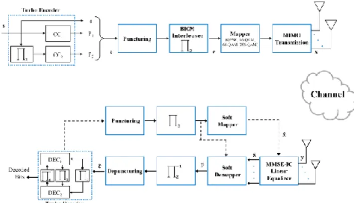
2.1 Transmitter scheme
The Block diagram of the adopted MIMO system is shown in figure 1. The source information bits are encoded by a turbo encoder, which concatenates in parallel two 8-state double binary recursive systematic convolutional (RSC) encoders [2]. The output codeword , made up of the source data and parities, is then punctured to reach a desired coding rate Rc. Bit
Interleaved Coded Modulation (BICM) [3] is used to disperse the obtained coded binary data sequence to assure that no single coded symbol is fully destroyed while passing through a fading channel. Punctured and interleaved bits are then gray-mapped to channel symbols according to the chosen constellation. Spatial multiplexing (SM) technique is then used to transmit the symbols among transmit antennas.
2.2 Receiver scheme
On the Receiver side, different components are linked together to achieve turbo processing by exchanging soft information in between components through both forward and feedback paths.. The MMSE-IC linear equalizer benefits from the a priori information from the feedback path and provides the estimated symbol vector ̃ of the input vector . Utilizing the max-log approximation method, the soft demapper produces the probabilities ̃ on transmit sequence in the form of log likelihood ratio (LLR), which after deinterleaving and depuncturing become the input ̃ to the decoder. The decoder uses Max-log-MAP decoding algorithm [4] and outputs extrinsic information, which after puncturing and interleaving along the feedback path serve as a priori information to the demapper. The soft mapper then provides the a priori information to the equalizer as decoded symbol vector ̂.
Figure 1: Block diagram of adopted MIMO system
3. MMSE-IC LE ALGORITHM
MMSE-IC is a linear filter based technique used to achieve equalization function. The algorithm is divided into two tasks: (1) the computation of filter coefficients and (2) the estimation of symbols.
The input vector of the MIMO turbo receiver shown in Fig.2 is given by the following expression:
(1)
where is vector of size of number of receiver antennas ( ), is a vector of size of number of transmitter antennas ( ), is the MIMO channel matrix of size , and is a vector of additive white Gaussian noise (AWGN) of size . The equalizer treats each of the symbols in vector as being distorted by the channel noise and by the other symbols in due to multiple antenna interference and tries to combat both. At the first iteration, no a priori information is provided by the soft mapper and ̂ is considered 0. Equation 1 can be written in the following form:
∑ (2) where – , hi and hj are the ith and jth
columns of matrix.
Using the Wiener filter ,the estimation of is given by:
̃ ̂ ̂ (3) where , ̂ is the jth element of vector ̂, hj
is the
jth column of matrix and (.)H is the Hermitian operator.
and are defined as follows:
(4) where ̂ (5) , and ̂ are respectively the constellation variance, noise variance, and the variance of the decoded symbols ̂. is identity matrix of size .
̂ (6)
where (7)
Equation 3 can be written as:
̃ ̂ ̂ (8)
where (9)
is the jth element of the bias vector .
4. NISC design approach
NISC represents a design approach of efficient custom processors by allowing the compiler to have low level control of hardware resources. The elimination of the instruction set increases the designer productivity and shrinks the time-to-market. Also the hardware is simplified due to the omitting of instruction decoder what reduces complexity and power consumption. NISC moves as much functionalities to the compiler. All major tasks of typical processor controller (instruction decoding, dependency analysis, instruction scheduling, etc.) are done by the compiler statically at compilation time [5]. The compiler generates the control words (CWs) that must be applied to datapath components at runtime in every clock cycle and loads them in the control memory. At run time the controller only loads the CWs and applies them to the datapath. NISC general architecture design is shown in figure 2.
The architecture description language (ADL) of NISC that is called Generic Netlist Representation (GNR) captures the structural information of NISC architecture. This information is used in the implementation, datapath completion, validation, optimization, and compilation. The datapath is captured in GNR [6] [7] that describes the components, ports, connections and aspects. A component can be a basic RTL component or a module, which is a hierarchical component that can have an internal netlist. Each component has different aspects that describe the behavior of the component for different tools in the approach toolset concerning compilation, synthesis, and simulation [8].
In some applications, the hardware must be controlled directly through specific instructions. Since NISC architectures have no predefined instruction-set, it does not have any assembly code to use specific resources with custom operations. To overcome this limitation, NISC uses pre-bound functions and variables that are mapped by the compiler to specific hardware resources [9]. During code generation, the compiler generates proper control bits to access their corresponding hardware resources. Pre-bound functions have no specific implementation and are treated similar to other operations. Therefore, they can be scheduled in parallel with other operations [9].
Figure 2: NISC general architecture design
5. Architecture design for MMSE-IC LE
The proposed architecture design for MMSE-IC LE supports the MIMO use in 2×2, 3×3, and 4×4 space-time coding for block, quasi-static, and fast fading channel models.5.1 Architecture choices
The equalization process is divided into two non-concurrent tasks: coefficient computation and symbol estimation. Allocating separate resources for each task will result in an inefficient architecture in case of quasi-static and block-fading channel. Hardware resources were shared between the two tasks to ensure efficiency and flexibility related to time selectivity of the channel. To meet flexibility requirements concerning the transmission diversity, complex matrix operations were broken down into real arithmetic ones. The hardware resources were allocated to perform complex operations using basic real arithmetic operators and efficiently reused to accomplish all required computations [10].
5.2 Architecture resources
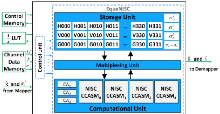
The proposed design, called EquaNISC, consists of three main modules: (1) storage unit, (2) multiplexing unit, and (3) computational unit in addition to a simple control unit. Figure 3 shows EquaNISC block diagram with its inputs and outputs blocks. The storage unit contains three groups of 16-bit registers. Each pair of registers is proposed to store a complex number, one storing the real part and the other the imaginary part. Each group can store one 4×4 complex matrix. The three groups of registers save data loaded from memory blocks or results of intermediate computations. The multiplexing unit is composed of multiplexers that construct a chain between different components of the proposed architecture. It arranges all data transfers in between storage unit, computational unit, input blocks, and output blocks. The computational unit contains all hardware resources that perform the required computations. It is mainly composed of complex adders and four instantiations of a combined complex adder, subtractor and multiplier module called NISC_CCASM [10] that can perform complex addition, subtraction, negation and conjugation. The channel data memory block saves the channel coefficient matrix H, the noise variance , and the received symbol vector y. The control memory block stores all the CWs generated by the compiler. The LUT block is a look-up-table that contains pre-computed positive inverse values used to retrieve the inverse value of the address. At each iteration, the soft mapper supplies EquaNISC with the soft values of the decoded symbol vector ̂ and its corresponding variance ̂. On the other hand
EquaNISC delivers the estimated symbol vector ̃ and
the corresponding bias vector g to the soft demmaper. Note that in all algorithm steps, fixed point arithmetic is used with carefully chosen precisions. All computational values are in signed 2’s complement representation [11].
Figure 3: Block diagram of the proposed architecture
6. Design flow and results
In our architecture, all basic components such as multiplexers, adders, subtractors, registers, shift registers, multipliers, converters, and memory blocks were described by their HDL description (i.e. Verilog). Hierarchical modules such as NISC_CCASM and EquaNISC units described using netlist description using GNR. Pre-bound functions were used to achieve efficient utilization of resources and accurate execution
timing. Different computational operations that can be executed in the same clock cycle were merged to the same pre-bound function to maximize the exploitation of hardware resources and time. Each pre-bound function describes all required control values of all resources used to perform the operation(s) in one clock cycle. Logic synthesis has been conducted targeting a Xilinx Virtex-7 XC7VX485T FPGA. The logic utilization of the design is shown in Table 1.
Table 1: FPGA Synthesis Results Xilinx Virtex-7 XC7VX485T
Slice Registers 2,029 out of 607,200 (0%) Slice LUTs 5,942 out of 303,600 (1%)
DSP48Es 12 out of 2800 (0%)
Frequency 192 MHz
To evaluate the influence of the adopted fixed-point arithmetic and the selected devised quantization the frame-error-rate performance for MIMO SM with 64-QAM was recorded. Figure 4 and figure 5 present the obtained frame-erroe rate (FER) curves compared to the reference floating point curves. The analysis of the results has shown a performance loss below 0.2 dB for 64-QAM and below 0.1 dB for QPSK.
Figure 4: Fig. 1. Floating-point vs. Fixed point-turbo equalization for 4×4 MIMO , 64-QAM , 192 source byte, 1/2 code
rate, fast fading Rayleigh channel
Figure 5: Fig. 1. Floating point vs. Fixed point turbo equalization for 4×4 MIMO , QPSK ,192 source byte , 1/2 code rate, fast fading
Rayleigh channel
7. Conclusion
In this paper, we presented a flexible application-specific processor dedicated for MIMO MMSE-IC linear equalization. The design supports flexibility requirement concerning the channel selectivity and transmission diversity. The processor architecture has been designed using NISC approach. Hardware resources are shared and reused by different computations to provide maximum utilization for different system configurations. The computational operations are organized efficiently, and their corresponding control signals are mapped directly to the hardware resources.
References
[1] M. Reshadi, "No-Instruction-Set-Computer Technology Modeling and Compilation," Thesis desiration 2007. [2] C. Douillard, M. Jezequel, C. Berrou, J. Tousch, N. Pham, and
N. Brengarth, “The Turbo Code Standard for DVB-RCS,” in Proc. of the International Symposium on Turbo Codes and Related Topics (ISTC), 2000, pp. 535–538.
[3] G. Caire, G. Taricco, and E. Biglieri, “Bit-interleaved coded modulation,” IEEE Trans. Inform. Theory, vol. 44, no. 3, pp. 927–946, May 1998.
[4] P. Robertson, P. Hoeher, and E. Villebrun, “Optimal and sub-optimal maximum a posteriori algorithms suitable for turbo decoding,” Eur. Trans. Telecommun. (ETT), vol. 8, no. 2, pp. 119–125, 1997.
[5] Mohammad Reshadi, “No-Instruction-Set-Computer
(NISC) Technology Modeling and Compilation”, PhD dissertation, University of California, Irvine, 2007. [6] B. Gorjiara, M. Reshadi, D. Gajski, "Generic
Architecture Description for Retargetable Compilation and Synthesis of Application-Specific Pipelined IPs", in
Proc. International Conference on Computer Design, ICCD, October 2006.
[7] B. Gorjiara, M. Reshadi, and D. Gajski, "GNR: A Formal Language for Specification, Compilation, and Synthesis of Custom Embedded Processors" in Processor
Description Languages: Applications and Methodologies,
Morgan Kaufmann, 2008.
[8] B. Gorjiara, M. Reshadi, P. Chandraiah, D. Gajski, “Generic Netlist Representation for System and PE Level Design Exploration”, in Proc. International Symposium
on Hardware/Software Codesign and System Synthesis, CODES+ISSS, October 2006.
[9] M. Reshadi, D. Gajski, “Interrupt and Low-level Programming Support for Expanding the Application Domain of Statically-scheduled Horizontally-microcoded Architectures in Embedded Systems”, in Proc. Design
Automation and Test in Europe, DATE’07, April 2007.
[10] M. Rizk, A. Baghdadi, M. Jezequel, Y. Mohanna,
Y. Atat, “Flexible and Efficient Architecture Design for MIMO MMSE-IC Linear Turbo-Equalization”, in Proc. IEEE Int. Conf. on Communications and Information Technology, ICCIT, 2013.
[11] M. Rizk, A. Baghdadi, M. Jezequel, Y. Mohanna,
Y. Atat, “Quantization and fixed-point arithmetic for MIMO MMSE-IC linear turbo-equalization”, in Proc. IEEE Int.