Dimensional Metrology of Non-rigid Parts
Without Specialized Inspection Fixtures
by
Vahid SABRI
MANUSCRIPT-BASED THESIS PRESENTED TO ÉCOLE DE
TECHNOLOGIE SUPÉRIEURE IN PARTIAL FULFILLMENT FOR THE
DEGREE OF DOCTOR OF PHILOSOPHY
Ph.D.
MONTREAL, MARCH 9, 2017
ÉCOLE DE TECHNOLOGIE SUPÉRIEURE UNIVERSITÉ DU QUÉBEC
© Copyright
Reproduction, saving or sharing of the content of this document, in whole or in part, is prohibited. A reader who wishes to print this document or save it on any medium must first obtain the author’s permission.
BOARD OF EXAMINERS
THIS THESIS HAS BEEN EVALUATED BY THE FOLLOWING BOARD OF EXAMINERS
Mr. Souheil-Antoine Tahan, Thesis Supervisor
Department of Mechanical Engineering at École de technologie supérieure
Mr. Xuan-Tan Pham, Thesis Co-supervisor
Department of Mechanical Engineering at École de technologie supérieure
Mr. Roland Maranzana, Chair, Board of Examiners
Department of Automated Production Engineering at École de technologie supérieure
Mr. Henri Champliaud, Member of the jury
Department of Mechanical Engineering at École de technologie supérieure
Mr. Luc Laperrière, External Evaluator
Department of Mechanical Engineering at Université du Québec à Trois-Rivières
THIS THESIS WAS PRENSENTED AND DEFENDED
IN THE PRESENCE OF A BOARD OF EXAMINERS AND THE PUBLIC FEBRUARY 28, 2017
ACKNOWLEDGMENTS
Firstly, I would like to express my sincere gratitude and my special thanks to my advisor Dr. S. Antoine Tahan and my co-advisor Dr. X. Tan Pham, professors in the department of Mechanical Engineering at École de technologie supérieure (ÉTS), for their continues support, great contributions, and encouragement of my PhD thesis, for their patience, trust, and motivation.
I would like to thank the president and the jury members of my PhD examination committee for reading my thesis and offering their insightful comments, suggestions, and encouragement.
Many thanks to our industrial partners, Bombardier Aero and Creaform3D, and also to ÉTS, CRSNG, and MITACS for their financial support and contribution.
Special thanks to my friends and my family: my parents and my sisters for supporting me spiritually throughout writing this thesis and my life in general.
At the end, I would like to express my appreciation to my beloved wife Sara who was always my support patiently in the moments when there was no one to answer my queries.
MÉTROLOGIE DIMENSIONNELLE DES PIÈCES NON RIGIDES SANS GABARIT DE CONFORMATION
Vahid SABRI
RÉSUMÉ
Le contrôle de qualité est un facteur important pour les entreprises manufacturières qui cherchent à prospérer à l’époque de la mondialisation, des pressions du marché et des progrès technologiques. La fonctionnalité et la qualité des produits ne peuvent pas être garanties sans cet aspect important. Les pièces fabriquées possèdent des déviations par rapport à leur forme nominale (CAO) à cause des variations inhérentes des processus de fabrication. Ainsi, l'inspection géométrique est un élément très important dans le contrôle de la qualité des pièces mécaniques. Nous allons nous concentrer ici sur l'inspection géométrique des pièces non-rigides (souples) qui sont largement utilisées dans les industries aéronautique et automobile. Les pièces non-rigides peuvent avoir des formes différentes dans une condition à l'état libre par rapport à leurs modèles nominaux en raison de l’effet des contraintes résiduelles et de la gravité. Pour résoudre ce problème, les gabarits de conformation, dédiés pour l'inspection, sont généralement utilisés dans l'industrie pour compenser le déplacement de ces pièces pour simuler l'état d'utilisation afin d'effectuer les inspections. Ces gabarits de conformité et les processus de l’installation et de l'inspection sont coûteux ; ils prennent beaucoup de temps. Notre objectif dans cette thèse est donc de développer une méthode d'inspection qui élimine le besoin des gabarits spécialisés. Ceci se fait par l’acquisition d’un nuage de points de la pièce à l'état libre en utilisant un appareil de mesure sans contact tel qu'un scanner optique et en le comparant au modèle CAO pour l'identification de déviations. En utilisant une méthode de localisation non-rigide et une analyse d’éléments finis, nous vérifions numériquement le profil d'une pièce non-rigide. Pour ce faire, un déplacement simulé est effectué en utilisant une définition améliorée des conditions aux limites de déplacement pour simuler des pièces non-fixées. Aussi, nous proposons une méthode numérique de métrologie dimensionnelle de pièces non-rigides à l'état libre basée sur la mesure de la longueur d'arc en calculant la distance géodésique à l'aide de la méthode de « Fast Marching » (FMM). Dans le cadre de cette thèse, nous appliquons nos méthodes développées sur des pièces industrielles non-rigides avec des surfaces de forme libre simulées avec différents types de déplacement, de défaut, et de bruit de mesure dans le but d’évaluer les performance métrologique des méthodes développées.
Mots-clés: contrôle de la qualité (QC), inspection géométrique, dimensionnement et
tolérancement géométrique (GD&T), tolérance de profil, localisation, pièce non-rigide / flexible / déformable / souple, conditions d'assemblage, métrologie.
DIMENSIONAL METROLOGY OF NON-RIGID PARTS WITHOUT SPECIALIZED INSPECTION FIXTURES
Vahid SABRI
ABSTRACT
Quality control is an important factor for manufacturing companies looking to prosper in an era of globalization, market pressures and technological advances. Functionality and product quality cannot be guaranteed without this important aspect. Manufactured parts have deviations from their nominal (CAD) shape caused by the manufacturing process. Thus, geometric inspection is a very important element in the quality control of mechanical parts. We will focus here on the geometric inspection of non-rigid (flexible) parts which are widely used in the aeronautic and automotive industries. Non-rigid parts can have different forms in a free-state condition compared with their nominal models due to residual stress and gravity loads. To solve this problem, dedicated inspection fixtures are generally used in industry to compensate for the displacement of such parts for simulating the use state in order to perform geometric inspections. These fixtures and the installation and inspection processes are expensive and time-consuming. Our aim in this thesis is therefore to develop an inspection method which eliminates the need for specialized fixtures. This is done by acquiring a point cloud from the part in a free-state condition using a contactless measuring device such as optical scanning and comparing it with the CAD model for the deviation identification. Using a non-rigid registration method and finite element analysis, we numerically inspect the profile of a non-rigid part. To do so, a simulated displacement is performed using an improved definition of displacement boundary conditions for simulating unfixed parts. In addition, we propose a numerical method for dimensional metrology of non-rigid parts in a free-state condition based on the arc length measurement by calculating the geodesic distance using the Fast Marching Method (FMM). In this thesis, we apply our developed methods on industrial non-rigid parts with free-form surfaces simulated with different types of displacement, defect, and measurement noise in order to evaluate the metrological performance of the developed methods.
Keywords: quality control (QC), geometric inspection, geometrical dimensioning and
tolerancing (GD&T), profile tolerance, registration, non-rigid / flexible / deformable / compliant part, assembly conditions, metrology.
TABLE OF CONTENTS
Page
INTRODUCTION ... 23
CHAPTER 1 REVIEW OF PREVIOUS RESEARCH ... 39
CHAPTER 2 FIXTURELESS PROFILE INSPECTION OF NON-RIGID PARTS USING THE NUMERICAL INSPECTION FIXTURE WITH IMPROVED DEFINITION OF DISPLACEMENT BOUNDARY CONDITIONS ... 45
2.1 Abstract ... 45
2.2 Introduction ... 46
2.3 Review of previous research ... 49
2.4 Proposed approach ... 52
2.4.1 Proposed approach based on the improvement of displacement boundary conditions ... 53
2.5 Case studies ... 56
2.6 Conclusion ... 64
2.7 Acknowledgments... 64
CHAPTER 3 A ROBUST AND AUTOMATED FE-BASED METHOD FOR THE FIXTURELESS DIMENSIONAL INSPECTION OF NON-RIGID PARTS USING AN IMPROVED NUMERICAL INSPECTION FIXTURE ... 65
3.1 Abstract ... 65
3.2 Introduction ... 66
3.3 Review of previous research ... 69
3.4 Proposed approach ... 73
3.5 Case studies, repeatability evaluation, and metrological performance analysis ... 78
3.7 Acknowledgments... 88
CHAPTER 4 A METHOD FOR DIMENSIONAL METROLOGY OF NON-RIGID PARTS BASED ON ARC LENGTH MEASUREMENT AT FREE-STATE CONDITION ... 89 4.1 Abstract ... 89 4.2 Introduction ... 90 4.3 Methodology ... 93 4.4 Case studies ... 96 4.5 Conclusion ... 103 4.6 Acknowledgments... 103 CONCLUSION ... 105 RECOMENDATIONS ... 109 BIBLIOGRAPHY ... 113
LIST OF TABLES
Page
Table 2.1 Displacement of parts in each zone induced by a force during inspection and their compliance behavior ... 49 Table 2.2 Results of defect’s amplitude ... 60 Table 3.1 The ratio δ tol in each zone induced by a force during inspection and
their compliance behaviour ... 69 Table 3.2 Capability and calculation time of corresponding search compared
between the 32b and the 64b versions of the GNIF algorithm ... 81 Table 3.3 Results of defect amplitudes in cases A and B (noise-free), and a
comparison between the original and the automatic method in case B ... 82 Table 3.4 Results of defect amplitudes in cases A and B with added noise for
repeatability evaluation (N 0, σ )** ... 83 Table 4.1 Algorithmic error (e in mm and e (%)) of the FMM in different
cases ... 96 Table 4.2 Case studies with the position and the nominal values of the defects,
and estimated values of the defects by each method ... 99 Table 4.3 Case studies with the position and the nominal values of the defects,
LIST OF FIGURES
Page
Figure 0.1 Special, expensive, heavy, and complex fixtures integrated with CMM for inspection of a flexible plate (Ascione and Polini 2010) ... 24 Figure 0.2 Main challenges in dimensional inspection of flexible parts with
dedicated fixtures in the industry ... 24 Figure 0.3 Measurement methods by (Beraldin 2010) ... 27 Figure 0.4 Registration of the measurement data with the nominal model
(Radvar-Esfahlan and Tahan 2012) ... 28 Figure 0.5 Restrained condition application (ASME-Y14.5 2009) ... 30 Figure 0.6 Comparison between the GNIF method and the Improved Numerical
Inspection Fixture (NIF) approach ... 34 Figure 0.7 Uncertainty of defect’s amplitude (maximum deviation) ... 34 Figure 0.8 The Dijkstra algorithm offers multiple short paths following always
the connections between the nodes. Fast Marching Method finds the optimal diagonal (shortest) path using the interpolation. (Garrido, Moreno et al. 2011) ... 36 Figure 0.9 Flowchart of the methodology in Chapter 4 ... 36 Figure 0.10 The methodology proposed in the cases with hole features. ... 36 Figure 0.11 A set of featured (strategic) points on a free-form part surface as well
as their pairwise geodesic distances along the surface ... 37 Figure 0.12 Thesis organization ... 37 Figure 1.1 Timeline for the simulated displacement methods of fixtureless
non-rigid inspection ... 44 Figure 1.2 Simulated displacement methods of fixtureless non-rigid inspection
based on the displacement direction ... 44 Figure 2.1 A special, expensive, heavy, and complex fixture for the inspection of
a flexible plate, Bombardier Aerospace Inc., left: the fixture without the part, right: the CAD model of the fixture with the part set up on it .... 47
Figure 2.2 Barycentric coordinates ( , , ) on an equilateral triangle ... 53 Figure 2.3 Flowchart of the proposed approach ... 55 Figure 2.4 Definition of boundary conditions (step 3); correspondence points
inside each constraint area and their correspondents on the scanned surface, centres of mass, and a displacement vector are illustrated (case A) ... 56 Figure 2.5 Non-rigid parts, Bombardier Aerospace Inc... 57 Figure 2.6 Simulated parts with different (but known) displacements and
deviations, after pre-alignment and rigid registration (step 1) ... 58 Figure 2.7 Correspondence search by GNIF (step 2) – example: cases A.S.T
(case A, small defects, torsional displacement) and B.S.T (case B, small defects, torsional displacement) ... 58 Figure 2.8 Displacement compensation by finite element analysis with defined
boundary conditions between the CAD model and the rigidly registered surface, in ANSYS® (step 4) – example: cases A.S.T and
B.S.T ... 59 Figure 2.9 Defect amplitudes (mm), positions, and areas, using inspection color
map – case A... 61 Figure 2.10 Defect amplitudes (mm), positions, and areas, using inspection color
map – case B ... 62 Figure 2.11 Defect amplitudes (mm), positions, and areas, using inspection color
map – case B.B.F with Gaussian measurement noise (0, ), = 0.02 ... 63 Figure 3.1 A costly, heavy, and complex fixture dedicatedly installed for the
dimensional metrology of a non-rigid plate mounted on it, Bombardier Aerospace Inc. ... 67 Figure 3.2 Flowchart of the proposed approach ... 75 Figure 3.3 Simulated displacement, identification of profile deviations ( ) and
estimation of maximum profile deviation ( ) on a defect ... 77 Figure 3.4 Non-rigid parts, Bombardier Aerospace Inc.; dimensions (mm) of case
A: 1750 × 1430, and case B: 1153.4 × 38.6; the material is aluminium
Figure 3.5 Simulated parts with different (but known) displacements and deviations, after pre-alignment and ICP rigid registration (step 1) ... 80 Figure 3.6 Correspondence search by the modified GNIF (step 2) – Examples:
ABF and BST ... 80 Figure 3.7 FE-based simulated displacement using Code ASTER® (Cuillière and
Francois 2014) (step 4) – Examples: ABF and BST ... 81 Figure 3.8 Defect amplitudes (mm), positions and areas, using inspection color
map – Case A (original, noise-free)... 84 Figure 3.9 Defect amplitudes (mm), positions and areas, using inspection color
map – Case B (original, noise-free) ... 85 Figure 3.10 Different uncertainty sources in the developed algorithm ... 86 Figure 3.11 Box Plots for the results of the maximum algorithmic error on profile
deviation (%) relative to in the cases A and B ... 87 Figure 4.1 Joint of two sections of a fuselage by considering the arc length
tolerance ... 91 Figure 4.2 Distance preserving property of non-rigid parts ... 93 Figure 4.3 Featured points on a skin panel and their geodesic distances (e.g.
, , ) ... 94 Figure 4.4 Cases A, B, and C; algorithmic error ( in mm and (%)) of the
FMM in plots ... 97 Figure 4.5 Case study applied in the adapted CPD (Aidibe and Tahan 2015); a)
CAD model with the nominal dimensions, and the manufactured part, b) positions of the imposed defects ... 98 Figure 4.6 A skin with free-form surface and hole features ... 101 Figure 4.7 Nominal geodesic distance (mm) – Algorithmic error ( ) (%) ... 101 Figure 4.8 Algorithmic error ( ) (%) in different displacement configurations
induced to a defect-free case ... 102 Figure C.1 Thesis contributions ... 108
LIST OF ABREVIATIONS
2D/3D Two/Three Dimensional Space ACPD Adapted Coherent Point Drift
ASME American Society of Mechanical Engineers
ASTER Analyses des Structures et Thermomécanique pour des Études et des Recherches
CAD Computer Aided Design
CASCADE Computer Aided Software for Computer Aided Design and Engineering CPD Coherent Point Drift
CMM Coordinate Measuring Machine DCS Design Coordinate System
FE Finite Element
FEA Finite Element Analysis
FEM Finite Element Method
FENR Finite Element Non-rigid Registration
FMM Fast Marching Method
GD Geodesic Distance
GD&T Geometrical Dimensioning and Tolerancing
GNIF Generalized Numerical Inspection Fixture GPS Geometrical Product Specifications
ICP Iterative Closest Point
IDI Iterative Displacement Inspection
ISO International Organization for Standardization
LTA Lighter Than Air
MCS Measurement Coordinate System
MDS Multidimensional scaling
NGD Nominal Geodesic Distance
QC Quality Control
RBF Radial Basis Function
RGNIF Robust generalized numerical inspection fixture
RM Rapid Manufacturing
RP Rapid Prototyping
LIST OF SYMBOLS AND UNITS OF MEASUREMENTS
∆ Displacement vector [mm]
⁄ Ratio between maximum profile deviation ( ) and tolerance of profile Profile deviations [mm]
Maximum profile deviation on a defect [mm]
Standard deviation of Gaussian measurement noise [mm] , , Barycentric coordinates ( + + = 1)
A/B.S/B.F/T Case A/B . Small/Big defects . Flexural/Torsional displacement . Average geodesic distance between a pair of holes [mm]
, Corresponding points inside each constrained area j on the CAD surface, and consequently their correspondents on the scanned data
, Set of correspondent pairs between two surfaces , ′ Centre of mass in ,
Deviation metrics, Algorithmic error [mm] or [%] Speed function with positive values
Nominal geodesic distance between two determined points or features on the CAD surface [mm]
Geodesic distance between two corresponding points or features on the scanned part surface [mm]
(0, ) Gaussian measurement noise [mm]
, , Featured points on a skin panel and their geodesic distances [mm]
ℝ m-dimensional Euclidean space
Set of featured points CAD surface
Scanned part surface Shortest traveling time
INTRODUCTION
Thesis problem definition
One of the main aspects for manufacturing companies to survive under globalization, market pressures, and technological developments is the quality control (QC) of products. Without regarding this aspect, it is not possible to be assured of the functionality and quality of products. Due to errors that occur during the manufacturing process, manufactured parts have deviations from their nominal geometry. Therefore, one of the important sections in quality control is the geometric inspection of products. With the help of computers, time and costs can be saved during the geometric inspection process.
Inspection fixtures integrated with coordinate measuring machines (CMM) are widely used in industry for geometric inspection. Non-rigid (or flexible) parts such as aeronautic products, that are the focus of this project, include deformations in the free-state condition due to factors such as weight and residual stress which cannot be completely and exactly quantified. Therefore, non-rigid parts are considered exceptions to the rule stated in standards such as (ASME Y14.5-2009) and (ISO 1101:2004) for Geometrical Dimensioning and Tolerancing (GD&T). These geometric inspections of manufactured parts are performed in a free-state condition. For the geometric inspection of non-rigid parts in industry, special fixtures integrated with CMM are usually used and a reasonable force (≈ 50 N) is imposed on the flexible parts during the inspection to compensate deformations of such parts for simulating the product’s functional state. These dedicated fixtures are very expensive, heavy and complex (Figures 0.1, 2.1, and 3.1), and they should be calibrated regularly. The flexible part needs to be precisely positioned on the inspection fixture. The time required for the fixture setup and the fixation process is typically more than 60 labor-hours. The other challenges are: dedicated and complex fixture design, inspection process and setup planning, and the production line stop (Figure 0.2). The proposed solution and the objective of this thesis, dimensional inspection of non-rigid parts without specialized fixtures (in a free-state condition), will be discussed in the following sections.
Figure 0.1 Special, expensive, heavy, and complex fixtures integrated with CMM for inspection of a flexible plate (Ascione and Polini 2010)
Figure 0.2 Main challenges in dimensional inspection of flexible parts with dedicated fixtures in the industry
Quality control and geometric inspection of mechanical parts
With the developments and improvements in rapid prototyping (RP), rapid tooling (RT), and
rapid manufacturing (RM), it is now possible to design and manufacture products with high
geometric complexity for application in industries such as aerospace and automotive. Therefore, product geometric inspection has an important role in the quality control of mechanical parts just after manufacturing, which usually consumes a large part of production lead time. Geometric specifications and design of a product are specified regarding functionality by means of Geometric Dimension and Tolerance (GD&T) of a product. The
• Material
• Operator & labor • Calibration,…
Cost
• Inspection fixture setup (typical > 60 hours) • Inspection process integrated with CMM • Production line stop,…
Time
• Inspection process and fixture design • Inspection setup planning,…
Difficulties & Complexities
GD&T inspection process is applied to verify the conformity of manufactured parts with the specification defined at the design stage. A reliable, efficient, and automated inspection process will decrease the product life cycle time and cost, improve industrial competition, and increase production efficiency (Gao, Gindy et al. 2006). Although geometric inspection methods and the equipment for rigid parts with regular geometric features have greatly improved and are generally available in the industry (Li and Gu 2005), the geometric inspection of non-rigid parts with free-form surfaces, especially without the use of inspection fixtures, has not been well studied.
Geometrical dimensioning and tolerancing
In mechanical engineering applications, free-form surfaces are assigned a profile tolerance to control surface variations (Li and Gu 2005). The surface profile should be controlled based on the principals and methods established in the standards of (ASME-Y14.5 2009) for GD&T (section 8, Tolerance of Profile). To control form or combinations of size, form, orientation, and position of a feature(s) relative to a true (nominal) profile, a tolerance zone is defined by using profile tolerances. This tolerance zone is a volume (3D), extending along the length and width (or circumference) of the regarded feature(s). The profile tolerance zone indicates a uniform or non-uniform tolerance boundary along the true profile within which the surface or its elements must lie. More details on tolerance zone boundaries, profile application, etc. are explained in the section 8, standards of (ASME-Y14.5 2009) for GD&T. Based on the application, the profile tolerance is defined with/without reference to a datum(s), which is called a related/individual profile tolerance (Li and Gu 2005). Regarding this research’s main objective (fixtureless inspection), tolerances will be defined without reference to a datum(s).
Measurement methods
In traditional methods for obtaining measurement data, skillful operators use particular techniques and equipment such as special gauges; thus these methods require much time and
cost. On the other hand, due to errors resulting from operator and measurement uncertainties they have low accuracy. (Li and Gu 2004)
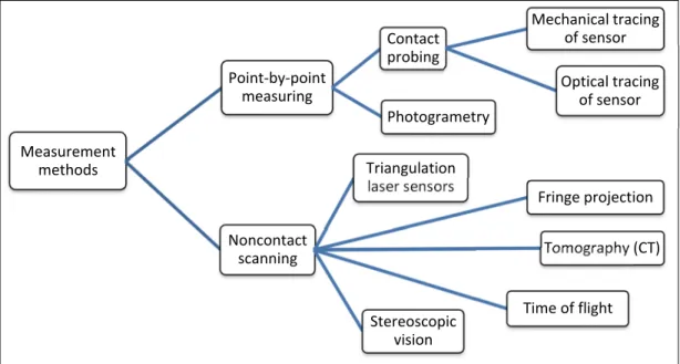
With developments in modern measurement systems, measuring operations have become much more accurate and quicker. Measurement data obtaining systems are divided into two main categories: contact measurement and non-contact measurement. (Savio, De Chiffre et al. 2007) presented a comprehensive review of measuring systems. A comparison of contact and non-contact measurement strategies is done in (Martínez, Cuesta et al. 2010), analyzing the applicability of contact and non-contact systems for measuring and control of tolerances. (Beraldin 2010) proposed a more exact classification (Figure 0.3). Regarding this classification, point-by-point measuring methods are:
• generally more accurate,
• more rapid for controlling a small number of entities and dimensions, • able to measure zones with difficult access more easily,
• not affected by reflectivity or transparency of objects. In contrast, the non-contact measuring methods are:
• much more rapid for measuring a non-prismatic surface,
• more rapid for controlling a big number of entities and dimensions, • able to measure, in some cases, inside and outside of a part,
• recommended for measuring flexible materials to avoid deformation of the part due to making contact.
One can choose an appropriate non-contact measuring method for a specific application regarding requirements such as accuracy, volume, flexibility, reflectivity, resolution, and portability (Beraldin 2010). For performing the fixtureless inspection in the free-state condition, the only option is the non-contact measurement because the contact measurement needs a physical fixture and positioning of the flexible part on it.
Figure 0.3 Measurement methods by (Beraldin 2010)
Registration (localization)
To compare the measurement data (point cloud obtained by a measurement method in the previous section) with the design (nominal, CAD) model for evaluating the deviations (and defects) with respect to the specified tolerance, it is essential to arrange these two surfaces in a common coordinate system. This process is called localization or registration. Traditionally, localization is performed by presenting the part at a favorite position and orientation using special tools, fixtures, etc. for inspection purpose. This kind of process is usually expensive and time-consuming, and needs time and effort to design and manufacture special fixtures. In recent and modern technologies, registration is done by the mathematical determination of a part’s positions and orientations in the design coordinate system (DCS) with respect to the measurement coordinate system (MCS). In application, registration can be done in two steps: finding the point-point corresponding relationship between scanned and nominal surfaces; and, finding an optimal transformation matrix between the DCS and MCS. (Li and Gu 2004), (Abenhaim, Tahan et al. 2011)
Measurement methods Point-by-point measuring Contact probing Mechanical tracing of sensor Optical tracing of sensor Photogrametry Noncontact scanning Triangulation laser sensors Fringe projection Tomography (CT) Time of flight Stereoscopic vision
Figure 0.4 Registration of the measurement data with the nominal model (Radvar-Esfahlan
and Tahan 2012)
Rigid registration (ICP)
(Li and Gu 2004) presented an extensive review of the rigid registration methods. (Besl and McKay 1992) developed the iterative closest point (ICP) algorithm, the most popular method for rigid registration of 3D shapes based on individual profile tolerance (without reference to a datum(s)) (Li and Gu 2005). The registration of two surfaces is performed by 3D transformations including rotations and translations. At each iteration, this algorithm calculates the optimal transformation matrix minimizing the Euclidean distance between two point clouds. Many variants of ICP have been developed improving all phases of the algorithm. Main advantages of ICP and its variants (Besl and McKay 1992):
• handling the full six degrees of freedom,
• independence from the shape representation (no need for a parametrical representation of the surfaces),
• need only for a procedure to find the closest point to a given point.
Generally, although ICP and its variations are the dominant methods for registration, they have an obvious limitation: two surfaces must be initially located close enough while
registering in order to determine the corresponding points which may be a difficult task when two surfaces have arbitrary positions and orientations in 3D space. (Li and Gu 2004)
A very recent method, 3-Points Convex Hull Matching (3PCHM), was proposed in 2016 by (Fan, Yang et al. 2016) for fast and robust point set registration by using the invariant property of the 3D convex hull. Considering the invariant property of 3D convex hull, the algorithm is not limited to the initial pose of the point set. Compared to the widely used algorithms (ICP and its variations), this method is more efficient and robust even in the presence of noise and outliers, it is also much quicker because the number of vertexes on the convex hull is smaller than the size of the point set. This registration method is limited when 1) there are a large number of outliers or noise outside the point sets, 2) the point set is sphere-like structure.
Non-rigid registration
The rigid registration methods are only applied for rigid parts whose shapes are similar (for example, two lines). Thus, they do not cover flexible parts in which the registration problem requires application of a non-rigid registration method in addition to finding a rigid mapping. The difference between rigid and non-rigid registrations is that non-rigid registration can align different shapes (for example, a line with a curve). (Abenhaim, Tahan et al. 2011) Many methods have been developed for non-rigid “surface / body / shape” registration such as the Multi-Dimensional Scaling (MDS) method (Borg and Groenen 2005), and the
Coherent Point Drift (CPD) algorithm (Myronenko and Xubo 2010), applied in medical
imaging, animation, etc. But the situation is different for the non-rigid registration of mechanical parts because of compliance behavior (flexibility) of a non-rigid part due to mechanical properties and material covariance. Therefore, we will take the advantage of the
finite element analysis method to consider mechanical properties and compliance behavior of
non-rigid part. In the next sections, we will discuss about non-rigid part and its compliance behavior.
Non-rigid (flexible) part, compliance behavior (flexibility)
According to the standards of (ASME-Y14.5 2009) and (ISO-1101: 2004), all tolerances are applied in a free-state condition unless otherwise specified. Exemptions to this rule are provided for non-rigid parts in the sections 4.20 and 5.5 of the ASME Y14.5 standard and by the (ISO-10579: 2010) standard.
Non-rigid parts are parts which may deform significantly from their defined tolerances due to their weight, flexibility or the release of residual stresses resulting from the manufacturing processes (free-state condition) (ASME-Y14.5 2009, ISO-10579: 2010). The mentioned standards allow for the application of a reasonable force (not exceeding the force excepted under normal assembly conditions) to make a deformation to conform the non-rigid parts within the specified tolerances. Depending on the functionality and design specifications, it may be necessary to assess the part subject to accepted restrained condition instead of, or in addition to, assessing the part in its free-state condition. These standards give rules for dimensioning and tolerancing non-rigid parts where the restraining of features is required during the verification of dimensions and tolerances specified on a drawing.
Figure 0.5 Restrained condition application (ASME-Y14.5 2009)
The (ASME-Y14.5 2009) standard states that in some cases “it may be desirable to restrain a part on its datum features to simulate their function or interaction with other features or parts”. Figure 0.5 illustrates a non-rigid part that should be restrained to its design shape by adding sufficient reinforcement (section 4.20). The maximum allowable free-state variation should be specified with an appropriate feature control frame where an individual form or location tolerance is applied to a feature in the free-state condition. In some cases, form or profile tolerances may be restrained. Because these surfaces may be subject to free-state variation, it is obligatory to denote the maximum force necessary to restrain each of them. The amounts of the restraining or holding forces and other requirements, required to simulate excepted assembly conditions, should be determined (section 5.5). (ASME-Y14.5 2009) Knowledge of the compliance behavior of a non-rigid part is an important factor to consider when specifying tolerances and evaluating the geometric and dimensional specifications of the part. According to the definition proposed by (Abenhaim, Desrochers et al. 2012), the compliance behavior of a non-rigid part is a relative notion based on the ratio between an applied force and its induced displacement. Based on the displacements induced by a reasonable force during inspection (around 50 N), the parts in zone A / B / C are considered rigid / non-rigid (flexible) / extremely non-rigid (see Table 2.1).
Another method for quantifying the flexibility of the mechanical part, from an industrial point of view, was proposed by Aidibe and Tahan (Aidibe and Tahan 2014). Their quantifying method is based on the ratio between the maximum displacement induced by a certain force and the profile tolerance of the non-rigid part. Our research is done on typical non-rigid mechanical parts used in the aeronautic and automotive industries.
Research objectives
The main objective is to eliminate the need for physical fixtures specialized for the inspection of non-rigid parts because of the challenges mentioned before (time, cost…). Therefore, we have to inspect such parts in a free-state (fixtureless) condition. The only option is non-contact measuring devices such as optical scanners which quickly measure the part by
obtaining a point cloud from its surface without the need for a physical fixture and positioning the part on it (free-state condition). Since the measured part and the nominal model are not in the same coordinate system, a registration process is necessary for a comparison between them to identify defects from deformations. For rigid parts, a rigid registration process is enough and any deviation from the nominal model is identified as a defect. In contrast, for non-rigid parts, a non-rigid registration technique is required in addition to the rigid registration method. As well, an identification step is critical for distinguishing between deformations and deviations. The mechanical properties as well as the compliance behavior of non-rigid parts should be considered for developing a more realistic method of fixtureless geometric inspection, which is also more practical and reliable.
Thesis organization
The methodology of this thesis is inspired by the real process of dimensional inspection of flexible parts in the industry: the flexible part should be positioned precisely on the inspection fixture to simulate the functional state. In this thesis, the nominal (CAD) model is used as the numerical (virtual) fixture (reference) that should be mapped into the scanned part for displacement compensation.
In terms of registration problems, the literature tells us that the best approach seems to be to search for the correspondence between two data sets (in our case, the CAD model and the scanned data). The GNIF method based on the isometric displacement (Radvar-Esfahlan and Tahan 2012) has some advantages that encourage us to use it to search for corresponding points between two data sets. In our previous work (Sabri, Tahan et al. 2016), presented as Chapter 2 in this thesis, we developed an approach to numerically inspect the profile tolerance of a non-rigid part using a non-rigid registration method and finite element analysis. To do so, a simulated displacement was performed using an improved definition of displacement boundary conditions for simulating unfixed parts. The developed method was applied on two industrial non-rigid parts with free-form surfaces simulated with different types of displacement, defect, and measurement noise (for one case). A conference paper entitled “Fixtureless Profile Inspection of Non-rigid Parts” was accepted to the proceedings
of the 43rd International Conference on Computers & Industrial Engineering 2013 (CIE 43) at the University of Hong Kong, Hong Kong on October 16-18, 2013. The paper entitled “Fixtureless Profile Inspection of Non-rigid Parts using the Numerical Inspection Fixture
with Improved Definition of Displacement Boundary Conditions” has been published in the International Journal of Advanced Manufacturing Technology – Springer London, February
2016, Volume 82, Issue 5, pages 1343-1352.
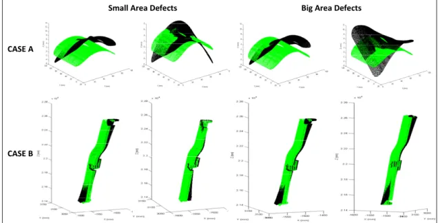
In Chapter 3, we improved the latter method and saved time by using an automatic node insertion and finite element analysis. Also, repeatability and robustness of the approach were studied. We applied the improved method on two industrial non-rigid parts; one from the previous work (case B) and a new one (case C). In addition, for repeatability and robustness evaluation, Gaussian measurement noise was introduced to each case three times (24 times for 8 cases). Therefore, the improved method was studied totally on 32 cases. The paper, entitled “A Robust and Automatic FE-based Method for the Fixtureless Dimensional
Inspection of Non-rigid Parts using an Improved Numerical Inspection Fixture”, has been
accepted for the publication in the International Journal of Advanced Manufacturing
Technology – Springer London (submission ID: JAMT-D-16-02890).
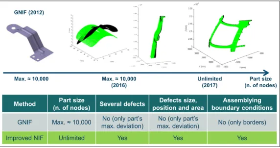
Figure 0.6 represents a comparison between the GNIF method and our proposed method (Improved Numerical Inspection Fixture). In the GNIF approach, borders are only used as a corresponding relationship for matching, by assuming them free of defects, whereas this situation generally does not conform to assembly conditions and real use state. Boundary conditions definition was improved in our approach based on assembly conditions. Also, the GNIF algorithm does not measure several defects (size, position, area) individually and only returns part’s maximum deviation, whereas in our improved approach, several defects (and their size, position, and area) can be measured separately. Also in the improved algorithm in Chapter 3, we eliminated the limitation for the part size (number of nodes) in the GNIF method by modifying the GMDS algorithm from the 32b version to the 64b version.
Part size (n. of nodes) Max. ≈ 10,000 (2016) Unlimited (2017) Max. ≈ 10,000
Method Part size
(n. of nodes) Several defects
Defects size, position and area
Assemblying boundary conditions
GNIF Max. ≈ 10,000 No (only part’s max. deviation)
No (only part’s
max. deviation) No (only borders) Improved NIF Unlimited Yes Yes Yes
GNIF (2012)
Figure 0.6 Comparison between the GNIF method and the Improved Numerical Inspection Fixture (NIF) approach
Gaussian measurement noise
Correspondence search
Displacement boundary condition formulation FE solver mm Biais measurement Uncertainty of [0.05-0.35] mm [0.01-0.44] mm [0.02-0.50] mm CAD Model Displaced CAD Model Scanned Part Defect on the Sanned Part Displacement Vectors
Figure 0.7 Uncertainty of defect’s amplitude (maximum deviation)
An improved version of Figure 3.10 in Chapter 3 is represented in Figure 0.7. Uncertainty of defect’s amplitude (maximum deviation) is the sum of Gaussian measurement noise and uncertainties in the displacement boundary condition definition, the correspondence search, and the FE solver. Gaussian measurement noise is known in our simulation process of
case studies, but the other uncertainty sources are unknown especially when they are combined together in the method’s algorithm. One solution to study these uncertainty sources could be to isolate each of them from the others and then to perform the validation research separately for each one. The minimum and maximum values (intervals) of algorithmic error (uncertainty of ) for each part are also illustrated in Figure 0.7.
Chapter 4 represents a new approach for the fixtureless inspection of extended arc tolerance and dimensional tolerance on free-form surfaces. We took advantage of the Fast Marching
Method (FMM) (Sethian 1996, Kimmel and Sethian 1998) for computing the geodesic
distance (shortest path) between each pair of points on the surface mesh. Therefore, there is no need for any special tool or fixture. The geodesic distance between any considered pair of points on the scanned part can be calculated using the Adapted FMM method as well without the need for any registration procedure. The algorithm was applied on several cases with curvature for studying the extended arc tolerance, and a comparison was done between the results of the proposed Adapted FMM method and the Adapted CPD method on the study cases in (Aidibe and Tahan 2015). The paper entitled “A method for Dimensional Metrology
of Non-rigid Parts based on Arc Length Measurement at Free-state Condition” has been
accepted with revisions to the International Journal of Advanced Manufacturing Technology
– Springer London (submission ID: JAMT-D-16-03929).
We have added some preliminary modifications to the third paper (Chapter 4) before final submission of its revised version. Figure 0.8 represents a comparison between the Dijkstra’s algorithm (Dijkstra 1959) and the Fast Marching Method (Sethian 1996, Sethian 1999, Sethian 2008) in finding multiple short paths or the optimal diagonal (shortest) path between two points. A brief flowchart of the proposed methodology is presented in Figure 0.9. Figure 0.10 is dedicated to the methodology proposed in the cases with hole features. Figure 0.11 illustrates a set of featured (strategic) points on a free-form part surface as well as their pairwise geodesic distances along the surface.
At the end of the thesis, we will present a conclusion and summarize the contributions made within the framework of our PhD study as well as our key recommendations for future works.
Figure 0.8 The Dijkstra algorithm offers multiple short paths following always the connections between the nodes. Fast Marching Method finds the optimal diagonal (shortest) path
using the interpolation. (Garrido, Moreno et al. 2011)
Determine the set of featured points × = 0 ⋯ ⋮ ⋱ ⋮ ⋯ 0 × ∀ , ∈ : − < Part accepted YES
Figure 0.9 Flowchart of the methodology in Chapter 4
= 1 = 1
=
= =
Figure 0.10 The methodology proposed in the cases with hole features.
×
Figure 0.11 A set of featured (strategic) points on a free-form part surface as well as their pairwise geodesic distances along the surface
Figure 0.12 Thesis organization
Chapter 2
• Paper 1: Fixtureless Profile Inspection of Non-rigid Parts using the
Numerical Inspection Fixture with Improved Definition of Displacement Boundary Conditions
• Accepted to the International Journal of Advanced Manufacturing
Technology
Chapter 3
• Paper 2: A Robust and Automatic FE-based Method for the Fixtureless
Dimensional Inspection of Non-rigid Parts using an Improved Numerical Inspection Fixture
• Submitted to the International Journal of Advanced Manufacturing
Technology
Chapter 4
• Paper 3: A method for Dimensional Metrology of Non-rigid Parts
based on Arc Length Measurement at Free-state Condition
• Submitted to the International Journal of Advanced Manufacturing
CHAPTER 1
REVIEW OF PREVIOUS RESEARCH
(Ascione and Polini 2010) dealt with the inspection of free-form surfaces belonging to non-rigid parts with inspection fixtures combined with CMM. In the following, the main methods based on simulated displacement approach developed for geometric inspection of non-rigid parts without the use of inspection fixtures, are described.
First effort for the fixtureless dimensional inspection of non-rigid parts was done by (Weckenmann and Gabbia 2006, Weckenmann and Weickmann 2006). They proposed the
virtual distortion compensation method in which the distorted part was deformed virtually
into the nominal model by displacing the point cloud obtained by non-contact scanning (fringe projection). They used feature extractions such as holes and edges for the corresponding relationship between the CAD model and measurement data, assuming the fixation points are free of defects. A triangle mesh of the surface from the obtained point cloud was generated, and then was transformed into a FEM model for simulating the fixation process using the information about the deviation of the assembly features from their actual position to their nominal position. The proposed method had some disadvantages; it was not completely automated due to the need for human challenges to identify the correlation between some special points and assembly conditions to find the boundary conditions of the FEA problem. Therefore, boundary conditions can be improved to simulate a real model of the fixation system. In addition, transforming the point cloud into a computer-aided analyzable model is a very time-consuming process. As well, parts with hidden structure or other details at the backside of a scanned surface cannot be easily modeled as a FEM model. (Weckenmann, Weickmann et al. 2007) improved the shortcomings in their last work by deforming the CAD model towards the measurement data in the virtual reverse deformation method. They enforce the boundary conditions on the nominal FE model using the known position of the fixation points on the scanned part. Therefore, pre-processing of the
measurement data is not needed. By this method, they decreased the time of inspection and
intervention in order to find the corresponding relationship between the CAD model and the measurement data. Moreover, modeling of the boundary conditions in the FEM dataset needs to be improved to simulate the unfixed part. Limitation of the method is uncertainties in measurement, model building and accuracy of the FEM simulation.
Similar to the virtual reverse deformation method, (Jaramillo, Boulanger et al. 2009, Jaramillo, Boulanger et al. 2011) proposed an approach which requires significantly less computing power, using the Radial Basis Function (RBF) to minimize the finite element mesh density required to predict correctly the behavior of the part. Recently in (Jaramillo, Prieto et al. 2013), they improved their method by performing flexible part registration using only partial views from areas that have to be inspected. They applied an interpolation technique based on RBFs to estimate positions of the missing fixation points since the partially scanned data may not contain all of them. During that same year, (Jaramillo, Prieto et al. 2013) proposed an approach for performing the inspection without the need for scanning the complete part’s surface or the areas near the fixation positions. In this algorithm, instead of typical fixation positions, surface feature points are used for computing the non-rigid transformation.
(Gentilini and Shimada 2011) proposed a new computational method for inspecting the final shape of a flexible assembly part by virtually mounting it into the assembly. After data acquisition from the shape by laser scanner, FEA is used to predict the post-assembly shape. First, a laser-digitized dense mesh is smoothed and decimated to be suitable for FEA. Then the part’s material properties are determined by a calibration process if not available. Next, specific displacement boundary conditions are applied to reproduce and simulate the assembly process. After FEA is executed, the quality inspection of the simulated
post-assembly shape is done using visualization tools such as light-reflection patterns and contour plots of the distance between the computed geometry and the target computer-aided design
(CAD) geometry. In addition, for validating the proposed method’s accuracy, the simulated post-assembly shape is compared with the actual post-assembly shape measured after physically assembling the part. This method can predict numerically the final shape of an assembled flexible part, reducing the time and the cost of product quality inspection.
However, the proposed method has the shortcomings mentioned before for the virtual distortion compensation method; the polygonal mesh data acquired by a laser digitizer requires post-processing steps, smoothing and decimation, because it suffers from uncertainties, noise and an excess number of polygons. The primary sources of noise are: physical phenomena such as the object’s spectral properties, surface texture, and lighting; and hardware-related issues such as digitizer calibration, lens typology, and camera resolution.
(Radvar-Esfahlan and Tahan 2012) introduced the Generalized Numerical Inspection Fixture
(GNIF) method which is based on the property that the inter-point shortest path (geodesic
distance) between any two points on the parts remains unchanged during an isometric
deformation (distance preserving property of non-rigid parts), in spite of large deformation.
Taking advantage of this property and inspired by a real industrial inspection process (locating the flexible part on the inspection fixture to simulate the use state), this method looks for some correspondence between the distorted part and the CAD model as the numerical inspection fixture. Through the ability of introducing a similarity measure using Multidimensional Scaling in order to find correspondence between two metric spaces, finite
element non-rigid registration (FENR) can be performed knowing some boundary conditions
as prior information and finding the correspondence to make the displacement. The geometric deviations between a deformed CAD model and measurement data can be calculated after finite element non-rigid registration. The main advantages of the GNIF method are the ability to inspect the parts with large displacements, taking the advantage of geodesic distance for finding correspondence, and using FEA method for making simulated displacement considering compliance behavior and mechanical properties. Another significant specification of GNIF is the capability for isometry-invariant partial surface matching in the existence of missing data. Correspondence search is also completely automatic. The main shortcoming of this method is that they use the borders as a corresponding relationship for matching, by assuming them free of defects, whereas this situation generally does not conform to assembly conditions and real use state. Boundary conditions can be improved based on assembly conditions. The authors in (Radvar-Esfahlan
and Tahan 2014) robustified the GNIF method by filtering out points that cause incoherent geodesic distances. The improved method is able to handle parts with missing data sets. In contrast to the aforementioned methods, (Abenhaim, Tahan et al. 2011) proposed the
iterative displacement inspection (IDI) algorithm that is not based on the use of a FE analysis
module. This method deforms iteratively the meshed CAD model until it matches the scanned part (measurement data). The proposed IDI algorithm is based on optimal step non-rigid ICP algorithms (Amberg, Romdhani et al. 2007) which combine non-rigid with non-non-rigid registration methods, as well as a developed identification method, to distinguish the surface deviations from the part’s distortion. This method essentially deforms the mesh in such a manner to assure its smoothness that prevents concealing surface defects and measurement noise during the matching process. (Aidibe, Tahan et al. 2011, Aidibe, Tahan et al. 2012) improved the identification module of the IDI algorithm, by proposing the use of a maximum-normed residual test to automatically set the identification threshold. However, the IDI method has some drawbacks. Due to lack of a FE analysis, the method depends on identifying some flexibility parameters, which are dependent on the thickness. In addition, they used the same number of nodes in the two point clouds.
(Aidibe and Tahan 2014) presented an approach that combines the curvature properties of manufactured parts with the extreme value statistic test as an identification method for comparing two data sets and to recognize profile deviation. This approach was tested on simulated typical industrial sheet metal with satisfactory results in terms of error percentage in defect areas and in the estimated peak profile deviation. As the core of the algorithm is based on the Gaussian curvature comparison, application of the method is limited to relatively-flexible parts where small displacements are predictable. The authors in (Aidibe and Tahan 2015) proposed the ACPD (Adapted Coherent Point Drift) method for optimization of the CPD algorithm in order to adapt it to the relatively-flexible parts problem, introducing two criteria: the stretch criterion between the nominal model and the aligned one, and the Euclidian distance criterion between the aligned nominal model and the scanned part.
(Abenhaim, Desrochers et al. 2015) introduced a method that registers the point cloud to the nominal model using information recuperated from the FE model of the nominal model. This is done by embedding a FE-based transformation model into a boundary displacement constrained optimization. The boundary displacement constrained optimization tries to minimize a distance-based similarity criterion between points in unconstrained areas whereas this criterion between points in constrained areas is maintained in a specified contact distance, and simultaneously, the restraining forces are limited. The latter allows for the inspection of non-rigid parts for which their functional requirements obligate to limit the restraining forces imposed during assembly. In addition, the point cloud does not need to be pre-processed into a FE model. Also, there is no need for manual identification of fixation positions in the point cloud. Furthermore, as long as the point cloud includes the restraining areas, a partial view of the part can be enough for the method.
The authors in (Wang, Zhou et al. 2016) used a 3D scanner to inspect a plate in the stamping forming process and to compensate the spring-back. The point cloud is converted to a polygonal object (mesh) of the part. The mesh is improved by repairing and filling the holes. Then by comparing the deformed part with the design model using the Geomagic Qualify software, its deviation and spring-back angle were obtained. This method is more accurate and complete than the traditional method (special fixture), and the spring-back compensation by this method can effectively reduce die tryout time.
Recently in (Thiébaut, Lacroix et al. 2017), an approach was proposed to evaluate shape deviations of flexible parts, using optical scanners, in a given measuring configuration for which the setup is known (whatever configuration, independent from the assembly conditions). The CAD model was displaced by the FE simulation of the part’s displacement due to its own gravity considering the known configuration used for the measurement. Having applied to a simple part, the form deviations were recognized by subtracting the simulated geometrical displacements to the measured geometrical displacements. They used the known configuration for the part’s optical measurement based on which the displacement vector for the FE simulation at each node of the CAD mesh was calculated using the intersection of a cylindrical neighborhood of its normal vector and the point cloud.
Figures 1.1 and 1.2 represent the aforementioned methods in a timeline and according to the direction of simulated displacement (scanned part towards CAD model or vice versa).
2004 2006 2007 2009 2010 2011 2014 2015 2016-2017 ISO-1101 2012 ISO-10579 ASME Y-14.5 Virtual distortion compensation (virtual Fixation) (Weckenmann et al.) Virtual reverse deformation (Weckenmann et al.)
Predicting and evaluating the post-assembly shape (Gentilini and Shimada)
FEM Trained Radial Basis Functions (Jaramillo et al.) Iterative displacement inspection (IDI) (Abenhaim et al.) Generalized numerical inspection fixture (GNIF) (R-Esfahlan and Tahan)
Robust generalized numerical inspection
fixture (RGNIF) (R-Esfahlan and Tahan)
Curvature estimation based approach (Aidibe and Tahan) Adapted coherent point drift algorithm (ACPD) (Aidibe and
Tahan) FE-based transformation model embedded into a constrained optimization
(Abenhaim et al.) Numerical inspection fixture
with improved definition of displacement boundary
condition (Sabri et al. )
CRIAQ MANU-501
Figure 1.1 Timeline for the simulated displacement methods of fixtureless non-rigid inspection
Figure 1.2 Simulated displacement methods of fixtureless non-rigid inspection based on the displacement direction
• Virtual distortion compensation (virtual Fixation) (Weckenmann et al. 2006) • Predicting and evaluating the post-assembly shape (Gentilini and Shimada 2011) • FE-based transformation model embedded into a constrained optimization
(Abenhaim, Desrochers et al. 2015) Scanned
part ↓ CAD model
• Virtual reverse deformation (Weckenmann et al. 2007)
• FEM Trained Radial Basis Functions (Jaramillo et al. 2011, 2013) • Iterative displacement inspection (IDI) (Abenhaim et al. 2011)
• Generalized numerical inspection fixture (GNIF) (Radvar-Esfahlan and Tahan 2012)
• Robust generalized numerical inspection fixture (RGNIF) (Radvar-Esfahlan and Tahan 2014)
• Curvature estimation based approach (Aidibe and Tahan 2014)
• Adapted coherent point drift algorithm (ACPD) (Aidibe and Tahan 2015) • Numerical inspection fixture with improved displacement boundary condition
(Sabri et al. 2015) CAD model
↓ Scanned
CHAPTER 2
FIXTURELESS PROFILE INSPECTION OF NON-RIGID PARTS USING THE NUMERICAL INSPECTION FIXTURE WITH IMPROVED DEFINITION OF
DISPLACEMENT BOUNDARY CONDITIONS
Vahid SABRI1, S. Antoine TAHAN1, X. Tan PHAM1, Dominic MOREAU2,
and Stephan GALIBOIS3
1. Department of Mechanical Engineering, École de Technologie Supérieure (ÉTS), Montreal, Canada 2. Bombardier Aerospace Inc., Montreal, QC, Canada
3. Creaform Inc., Levis, QC, Canada
This chapter has been published in the “International Journal of Advanced Manufacturing
Technology” – Springer London, February 2016, Volume 82, Issue 5, pages 1343-1352.
2.1 Abstract
Quality control is an important factor for manufacturing companies looking to prosper in an era of globalization, market pressures, and technological advance. The functionality and product quality cannot be guaranteed without this important aspect. Manufactured parts have deviations from their nominal (CAD) shape caused by the manufacturing process. Thus, geometric inspection is a very important element in the quality control of mechanical parts. We have focused here on the profile inspection of non-rigid parts which are widely used in the aeronautic and automotive industries. Non-rigid parts can have different forms in a
free-state condition compared with their nominal models due to residual stress and gravity loads.
To solve this problem, dedicated inspection fixtures are generally used in industry to compensate for the displacement of such parts for simulating the use state in order to perform geometric inspections. These fixtures and the inspection process are expensive and time-consuming. Our aim is therefore to develop an inspection method which eliminates the need for specialized fixtures by acquiring a point cloud from the displaced part using a contactless measuring system such as optical scanning and comparing it with the CAD model for the identification of deviations. Using a non-rigid registration method and finite element
analysis, we will numerically inspect the profile of a non-rigid part. To do so, a simulated displacement is performed using an improved definition of boundary conditions for simulating unfixed parts. In this paper, we will apply an improved method on two industrial non-rigid parts with free-form surfaces simulated with different types of displacement, defect, and measurement noise.
Keywords: quality control, geometric inspection, geometric dimensioning and tolerancing,
profile tolerance, registration, non-rigid/flexible/deformable part, assembly conditions, metrology.
2.2 Introduction
Geometric inspection has an important role to play in the quality control of mechanical parts since it usually consumes a large portion of production lead time. By means of Geometric Dimensioning and Tolerancing (GD&T), geometric specifications and product design are specified according to functionality. To verify whether manufactured parts meet specifications defined at the design phase, the GD&T inspection process is applied. By using a reliable, efficient, and automated inspection process, product life cycle time will decrease and industrial competition will improve (Gao, Gindy et al. 2006). Although the methods for geometric inspection of rigid parts have significantly improved and are generally available within the industry (Li and Gu 2005), the geometric inspection of non-rigid parts with free-form surfaces has not been well studied.
In mechanical engineering applications, surfaces are allocated a profile tolerance to control manufacturing variations (Li and Gu 2005). A surface profile should be controlled based on the principles established by the ASME Y14.5-2009 standards (section 8) (ASME-Y14.5 2009). According to these standards (or ISO 1101:2004, ISO-GPS standards (ISO-1101: 2004)), unless otherwise specified, all tolerances should be applied in a free-state condition. Exemptions are agreed to this rule for non-rigid parts. In these cases, non-rigid parts may deform significantly from their defined tolerances due to their weight (gravity), or the release
of residual stresses resulting from manufacturing processes (ASME-Y14.5 2009, ISO-10579: 2010).
Generally, to solve the above-mentioned problem, special inspection fixtures with complex setups are used within the industry to compensate for the displacements to simulate use state in order to perform geometric inspection. These dedicated fixtures are expensive, heavy, and complex (Figure 2.1). The process is extremely time-consuming which reduces competitiveness. The mentioned standards also allow for the application of reasonable load (not exceeding the load expected under normal assembly conditions) to displace non-rigid parts to conform to the specified tolerances. The solution is to develop an inspection technique which eliminates the need for specialized fixtures by acquiring a point cloud from the displaced part using a contactless measuring system such as optical scanning and comparing it with the CAD model for the identification of deviations.
Figure 2.1 A special, expensive, heavy, and complex fixture for the inspection of a flexible plate, Bombardier Aerospace Inc., left: the fixture without the part,
right: the CAD model of the fixture with the part set up on it
For the purpose of comparing the measurement data (point cloud) with the nominal model, it is necessary to dispose these two sets in a joint coordinate system. This procedure is called
registration. In recent and modern technologies, this registration is mathematically defined
using the translation and the rotation of the Design Coordinate System (DCS) with respect to the Measurement Coordinate System (MCS). In application, registration can be done in two steps: searching for the corresponding relationship between scanned and nominal surfaces,
and finding an optimal transformation matrix between the DCS and MCS. The rigid registration methods are only applied for rigid parts whose shapes are similar. Thus, they do not cover flexible parts in which the registration problem requires application of a kind of non-rigid registration method in addition to finding a rigid mapping. The difference between rigid and non-rigid registrations is that a non-rigid registration can align two different shapes (for example, a line with a curve) (Li and Gu 2004, Abenhaim, Tahan et al. 2011). Several rigid and non-rigid registration methods have been developed such as the Iterative Closest
Point (ICP) algorithm (Besl and McKay 1992) and its variants for rigid registration; the Multi-Dimensional Scaling (MDS) method (Borg and Groenen 2005), and the Coherent Point Drift (CPD) algorithm (Myronenko and Xubo 2010) for non-rigid registration applied
in medical imaging, animation, etc. However, the situation for the registration of a non-rigid mechanical part is different due to the result of its compliance behavior.
Compliance behavior of a compliant (flexible) part is an essential issue to study while specifying tolerances and assessing the geometric and dimensional specifications for the part. This factor is a relative concept based on the relation between an imposed force and its persuaded displacement (Abenhaim, Desrochers et al. 2012). Based on the displacements of parts induced by a reasonable force (50°N) during inspection, the parts are considered rigid/non-rigid (flexible)/extremely non-rigid (see Table 2.1). Another method for quantifying flexibility of the mechanical part, from an industrial point of view, was proposed by Aidibe and Tahan (Aidibe and Tahan 2014). Their quantifying method is based on the ratio between the maximum displacement induced by a certain force and the profile tolerance of the non-rigid part. Our research is done on typical non-rigid mechanical parts used in the aeronautic and automotive industries.
The following paper includes four sections: a review of previous researches for the fixtureless geometric inspection of non-rigid parts, the developed method, case studies including the presentation of metrological performances of our method, and finally, a conclusion.
Table 2.1 Displacement of parts in each zone induced by a force during inspection and their compliance behavior
⁄ by a reasonable force during inspection (≈ 50 N) Compliance behavior
δ⁄ < 5-10 % Rigid
δ⁄ > 5-10 % (e.g. thin shell, skin in aeronautic and
automotive parts) Non-rigid (flexible) δ⁄ ≫ 10 % (the shape depends on the part’s weight and
position, such as thin seals and paper) Extremely non-rigid
2.3 Review of previous research
Ascione and Polini (Ascione and Polini 2010) dealt with the free-form surface inspection of non-rigid parts using inspection fixtures combined with CMM. Abenhaim et al. (Abenhaim, Desrochers et al. 2012) presented a review of the previous researches for the fixtureless inspection of non-rigid parts and proposed a classification of the specification methods used for the GD&T of non-rigid parts under the ASME and ISO standards. In the following, we will introduce the primary methods, based on the simulated displacement approach, developed for the geometric inspection of non-rigid parts without the use of inspection fixtures.
For the first time in 2006, Weckenmann et al. (Weckenmann and Gabbia 2006, Weckenmann and Weickmann 2006) made strides in the fixtureless inspection of non-rigid parts by proposing the virtual distortion compensation method in which they virtually displaced the distorted part into the nominal model by displacing the point cloud captured by a contactless scanning device. A triangle mesh of the surface from the point cloud was generated and transformed into a finite element analysable (FEA) model. Afterwards, the fixation process was simulated using information about the assembly features’ deviation from the actual (measured) to the ideal (nominal) position. This method requires human intervention to recognize the correlation between some determined points and assembly conditions in order to define the boundary conditions of the FEA problem. Therefore, boundary conditions can be improved to simulate a real model of the fixation system. In addition, converting the point