HAL Id: hal-01240241
https://hal.archives-ouvertes.fr/hal-01240241
Submitted on 8 Dec 2015
HAL is a multi-disciplinary open access
archive for the deposit and dissemination of
sci-entific research documents, whether they are
pub-lished or not. The documents may come from
teaching and research institutions in France or
abroad, or from public or private research centers.
L’archive ouverte pluridisciplinaire HAL, est
destinée au dépôt et à la diffusion de documents
scientifiques de niveau recherche, publiés ou non,
émanant des établissements d’enseignement et de
recherche français ou étrangers, des laboratoires
publics ou privés.
Method Taking into Account Process Dispersions to
Detect Hardware Trojan Horse by Side-Channel
Xuan Thuy Ngo, Zakaria Najm, Shivam Bhasin, Sylvain Guilley, Jean-Luc
Danger
To cite this version:
Xuan Thuy Ngo, Zakaria Najm, Shivam Bhasin, Sylvain Guilley, Jean-Luc Danger. Method Taking
into Account Process Dispersions to Detect Hardware Trojan Horse by Side-Channel. PROOFS:
Security Proofs for Embedded Systems 2014, Sep 2014, BUSAN, South Korea. �hal-01240241�
Dispersions to Detect Hardware Trojan Horse
by Side-Channel
Xuan Thuy NGO1, Zakaria NAJM1, Shivam BHASIN1, Sylvain GUILLEY1,2 and Jean-Luc DANGER1,2
1
Institut MINES-TELECOM, TELECOM-ParisTech CNRS LTCI (UMR 5141)
2
Secure-IC S.A.S.
Abstract. Hardware trojan horses inserted in integrated circuits have received special attention of researchers. Most of the recent researches focus on detecting the presence of hardware trojans through various techniques like reverse engineering, test/verification methods and side-channel analysis (SCA). Previous works using SCA for trojan detection are based on power measurements or even simulations. When using real silicon, the results are strongly biased by the process variations, the exact size of the trojan and its location. In this paper, we propose a metric to measure the impact of these parameters. For the first time, we give the detection probability of a trojan as a function of its activity, even if untriggered. Moreover we use electromagnetic (EM) as side-channel as it provides a better spatial and temporal resolution than power measurements. We conduct a proof of concept study using an AES-128 cryptographic core running on a set of 10 Virtex-5 FPGA. Our results show that, using this metric, there is a probability superior than 99% with a false negative rate of 0.017% to detect a HT bigger than 1% of the original circuit.
Keywords: Hardware Trojan (HT), Trojan detection, False negative probabil-ity, Electromagnetic Measurements, Side-Channel Analysis, Process Variation, FPGA.
1
Introduction
The trust and security of Integrated Circuits (IC) design and fabrication is critical for sensitive fields like finance, health, and governmental communications. Due to the complexity and the high cost of IC fabrication cycle, more and more firms outsource their circuit. This trend gives a possibility to introduce malicious circuit, called hardware trojan horse (HT) in any IC. It can either perform a Denial Of Service (DOS), steal sensitive information or deteriorate circuit performance [14]. A recent example can be seen in findings of Skorobogatov et al. [13], where a backdoor was found in a military grade IC. The backdoor allowed an attacker to
disable and reprogram all security of the chip. Therefore, the HT are considered a real threat which has gained attention from researchers since the last decade.
HT circuit is composed of two parts: • Trigger: used to activate the HT.
• Payload: used to realize the malicious function.
It can be inserted at any point during the design or fabrication process from Register Transfer Level (RTL) to layout and circuit fabrication. In [8], authors show some techniques to insert HT at RTL level. These HT, which are activated with a specific pattern inputs, can leak secret key via RS232 channels. In [4], authors insert their HT at mask level (GDSII). This HT injects a fault in AES cipher to facilitate key recovery through fault attacks.
The HT, unlike software trojans, cannot be removed once it is fabricated. So it is important to detect these HT before they become effective, either with reverse engineering, during the test phase or at run-time. The amount of efforts required to detect an HT also varies according to the point of insertion. For instance, an HT is easier to detect at RTL or Netlist level if infected source codes are available, which is unlikely. Detection becomes a big challenge at GDSII and fabrication level.
Previous works classify detection methods into two wide categories: destructive and non-destructive. Destructive methods comprises of destructive reverse engi-neering. This means that we destroy the chip to reconstruct GDSII and Netlist level of the chip using chemical products and optical materials as Scanning Optical Microscopy (SOM), Scanning Electron Microscopy (SEM), pico-second imaging circuit analysis (PICA) etc. The main advantage of this technique is its accuracy with which it can detect all malicious insertions. However, the destructive nature and lengthy times needed to reconstruct the netlist of the chip are a significant drawback. To avoid the destruction of ICs, certain non-destructive methods were introduced, which further can be classified as: invasive and non-invasive. Invasive methods consist to modify IC structures in conception phase (RTL, Netlist levels) to prevent the HT insertions or to assist other detection techniques.For example in [2], authors propose a tool for protection of IP sent by a mechanism of key exchanges protecting both the customer and supplier.
Non-invasive methods compare the physical characteristics or logical state of an IC with a genuine circuit also known as the “golden circuit” at testing time or run-time. In [1], authors propose to add re-configurable DEsign-For-ENabling-SEcurity (DEFENSE) logic to the functional design. In test time, the first approach is using logic testing. It involves applying test patterns at the input and try to detect anomalous behaviors of ICs [3] [7]. But almost all test-time detection techniques are difficult to realize. They cannot ensure that HT will be activated because of the complexity of test patterns.
Therefore, Side-Channel Analysis (SCA) can also be deployed to detect HTs, which observes and compares physical traits (example power consumption, time delay etc) of an IC under test against a trusted IC named “golden circuit” [11,12]. By comparing the detection methods, SCA seems to be one of the best approach to detect HT because IC physical characteristics will be altered when the internals
of an IC are modified. It can detect almost any kind of HT, however it does need a trusted reference or “golden circuit” which may not always be available. Sometimes, destructive reverse engineering can be applied on a small set of IC to obtain a golden model and then use them to detect HT in other circuits with SCA.
To our knowledge, previous works on SCA-based detection have been limited to either simulations or power consumption measurements on some real circuit. In [9], authors present a practical evaluation of HT detection using SCA on FPGA. But the experiments were performed on a single FPGA so the process variations were not taken into account. The placement and routing of original circuit in golden model and infected models are not the same in the experiment, which makes it hard to quantify the effect of HTs alone. In this paper, we propose a metric to evaluate the impact of process variations, HT sizes, HT placements in HT detection. Process variations are studied on 10 different samples of Virtex 5 FPGA (LX30). We keep the same placement and routing of original circuit, using Xilinx FPGA Editor, in all circuit versions (golden and infected) to imitate the real scenario of HT insertion on ICs. Our work on HT detection is done using ElectroMagnetic (EM) measurements.
The rest of this paper is organized as follows. Sec. 2 gives our metrics rationale. Sec. 3 presents the scenario of our study. It also shows which and how the HT was implemented in FPGA without changing placement and routing. Sec. 4 shows the results of our study. We give an estimation of the probability of detecting an HT as a function of its size. We also studied the impact of process variations and placements of HT on EM measurements. Sec. 5 gives a discussion about our results and SCA-based detection methods. We finish with a small conclusion and some perspectives in Sec. 6.
2
Metrics Rationale
2.1 How to Build a Reference Model
The reference to build a SCA detection method keeping these parameters constant: • The temperature.
• Power supply voltage. • The acquisition setup.
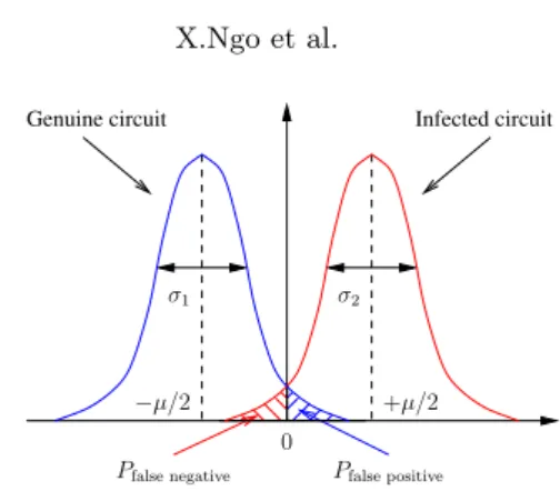
But even with this similar environment, the circuits are always sensitive to process variations (PV), thus deteriorating HT detection efficiency. Indeed two circuits fabricated with the same process, and in the same wafer, have different physical and electrical behaviors. The process variation effect on EM measurement can be modeled by a random noise with a Gaussian distribution [5]. On the other hand, the impact of the HT comes mainly from the trigger block which generates an increase of consumption or EM activity. Therefore the HT contribution to the side-channel (e.g., the EM field) can be modeled by an activity offset on a net used by the HT. This is illustrated on figure 1.
Genuine circuit Infected circuit −µ/2 +µ/2 0 σ1 σ2 Pfalse positive Pfalse negative
Fig. 1: EM field for genuine and HT infected circuit
This figure illustrates the activity distribution at a specific sample time and for a set of reference devices. The blue Gaussian curve is the activity distribution without any HT. And the red Gaussian curve is the distribution through the same set of circuits which contains the infected AES (with HT). It is merely an offset which depends on the HT size, placement and position relative to the probe in case of EM acquisition. Using this model, the probability of detecting a HT can be calculated. Precisely, we can estimate the false positive and false negative probability of HT detection as a function of HT size for a set of ICs.
False Negative Probability Computation Theory By definition, the false positive probability is the probability of rejecting a genuine circuit. It corresponds to the blue area in figure 1. The false negative probability is the probability to accept an infected circuit. It corresponds to the red area in figure 1. These two distributions have the same standard deviation (σ1≈ σ2= σ) as the HT impact
corresponds to a shift of the mean value. So the false negative probability is almost equal to false positive probability and only one needs to be calculated.
The Gaussian probability curve with a mean of µ2 and a standard deviation of σ is presented by the following equation:
P0(x) = 1 √ 2πσ2 · exp − (x −µ2)2 2σ2 . (1)
Hence the false negative and false positive probability are calculated as follows:
Pfalse negative= Pfalse positive=
Z 0 −∞ 1 √ 2πσ2· exp − (x −µ2)2 2σ2 dx . (2)
These equations can also be written as:
Pfalse negative= Pfalse positive =
1 2 − 1 2 · erf( µ 2σ√2) , (3)
In this equation, erf is error function defined as follows: erf(x) = √2 π Z x 0 exp (−t2) dt . (4)
This equation can estimate the false positive and false negative probability of HT detection for each HT size and position. The following sections show our results using this model for EM leakage. In [6], the authors also give the same proposition to evaluate the false positive and false negative probability. But they used delay measurements and simulations to perform the result. In this article, we apply this approach on the EM measurement which give a better spatial and temporal resolution and we do not need to add extra circuit in the test circuit (as delay measurement circuit). Furthermore, we realized experiment on a set of FPGAs to visualize the real impact of process variations on the detection method. First a description the experimental platform is presented.
3
Setup Description
The proof-of-concept is done on FPGA setup based on Virtex-5 (LX30) FPGA from Xilinx. In the following, we provide details of the HT inserted along with the AES-128 crypto-processor for our study. Next we present the technique used to insert HT in an FPGA, without modifying the placement and routing of the original circuit. The description of the measurement setup is also detailed in Appendix A.
FPGAs are hardware emulation platforms of ASICs. So, we model (at lower cost!) with an FPGA what we would need to do with an ASIC: send the tape-out database to an untrusted off-shore entity like a foundry, and insert a HT in a circuit before fabrication. Even the technology used for fabricating a ASIC is same as for FPGA (CMOS process). The only difference lies in the tricks and techniques used to insert the HT without disturbing the circuit. In Xilinx, one can use circuit representation in FPGA Editor or XDL to achieve it. On the other hand, the techniques used in IC should be totally different, for instance, “ECO-placement” in Cadence Encounter. (ECO means “Engineering Change
Order”, and consists in applying small and local modifications to the layout to fix minor timing violations or to improve the yield before going to tape-out.) However the result can still be extended from FPGAs to ASICs.
3.1 Trojan Description
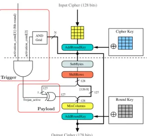
We synthesized and implemented a AES-128 crypto-processor on the FPGA along with a simple UART controller for communication with the outside world. This AES circuit needs one clock cycle to compute one round or 11 clocks for the whole encryption process. Figure 2 presents the HT inserted in AES. The HT Trigger is composed of 2 activation conditions:
• When N least significant bits (LSB) of 128 bits at the output of AddRoundKey are at “1”.
The HT payload is an XOR gate that will inject a fault in the inner eighth round when HT is activated. This HT structure can aid the attacker to perform faults compliant with Piret’s DFA [10] if HT is connected to the N least significant bits (LSB) of 128 bits of plaintext.
To evaluate the impact of HT sizes, we created 3 versions of the same HT, each time varying the generic parameter N as:
• Trojan 1: HT with the parameter N = 32, around 0.5 % of the original circuit.
• Trojan 2: HT with the parameter N = 64, around 1 % of the original circuit. • Trojan 3: HT with the parameter N = 128, around 1.7 % of the original
circuit.
We also study the impact of placement of the HT with respect to the original circuit, realized using Trojan 3 as:
• Placement 1: Trojan 3 placed within the boundary of AES crypto-processor. • Placement 2: Trojan 3 placed outside the boundary of AES crypto-processor
in a far-off corner of the FPGA.
• Placement 3: Trojan 3 placed outside the boundary of AES crypto-processor and dispersed over the FPGA.
In total, we created 7 different designs: a HT-free design (golden circuit) and 6 infected versions with different sizes and placement.
3.2 Trojan Insertion
In order to evaluate the impact of HT in FPGAs, we need to keep the same placement and routing between the golden circuit and HT infected circuit. Hence the only difference between the two is the logic utilized for implementing the HT logic. To insert a HT in an Virtex 5 FPGA, without modifying the routing, we follow the following steps:
1. Synthesize, Translate, Map, Place & Route the original circuit.
2. Extract the Native Circuit Description (NCD) file which contain all the circuit, placement & routing information of original circuit for golden model. 3. Open the NCD file using FPGA Editor tool and insert HT in unused LUTs
and Slices of FPGA, manually or by a script.
4. Generate bit files for both original and HT infected model with FPGA Editor. With this method we can ensure that the placement and routing of original circuit is the same in both golden and HT-infected circuit. Figure 3(a) shows the placement and routing of the original (golden) circuit and Figure 3(b) is the placement and routing of infected circuit with a HT of size 1.7% of the golden circuit. The Trojan 1 needs 7 LUTs, the Trojan 2 needs 14 LUTs and the Trojan
AddRoundKey MixColumns AND Grid ShiftRows SubBytes Cipher Key Round Key AddRoundKey
Input Cipher (128 bits)
127 Trojan_active 127 128 128 [126:0] 127 1
Output Cipher (128 bits) activation_cond[1] (8th round) activation_cond[2]
Payload Trigger
N
Fig. 2: Trojan inserted on AES 128 bits
3 needs 27 LUTs to perform. For each Trojan, the payload part needed only one LUT and the rest is trigger part.
The platform of our measurement setup is presented in Appendix A. The following section presents the experimental results.
4
Results
In this section, we apply statistical tools to enable HT detection by side-channel measurement. A single EM trace is shown in Figure 5. The circuit is clocked with a frequency of 24 MHz. It is known that EM measurements generally possess a higher SNR than power measurements because of the directivity of the EM probes. EM probes can be spatially more selective and can be made to capture the activity of the stimulated region only. Regarding the EM trace in Figure 5, we noticed that the SNR seems good thanks to average done by oscilloscope. We also found all cipher computation rounds in this trace.
4.1 HT Detection Feasibility with Process Variations In Figure 4 we plotted the difference |Gj,1− E
10(G1)| of all golden circuit inserted
in 10 FPGA in green, and |T10,1− E
10(G1)| of HT test circuit in red. Our notations
are defined below:
– Gj,1 is the EM trace for first plaintext of jth golden circuit,
– T10,1 is the EM trace for first plaintext of the infected circuit inserted in
(a) (b)
Fig. 3: Placement and routing of circuits on FPGA Virtex 5. for (a) AES 128 bit without HT and (b) AES 128 bit with HT 1.7%
– E10(G1) is the EM trace mean for first plaintext of all 10 golden circuit.
We can notice the static differences between green (or gray) curves that are due to process variations. We also noticed that the difference of EM Measurement in red (or black) for AES with HT 1 (0.5%) is bigger than the fluctuation of process variations for certain places thus allow the possibility to detect this HT. This clearly shows that the insertion of HT is detectable if we choose specific points of interest. 1350 1400 1450 1500 1550 0 100 200 300 400 500 600 700 800 Samples Absolute of differences Geniune AES AES & HT 2
0 500 1000 1500 2000 2500 3000 −2 −1.5 −1 −0.5 0 0.5 1 1.5x 10 4 Samples EM emanation
Fig. 5: EM Measurement for single encryption.
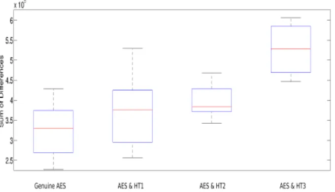
4.2 Hardware Trojan Detection Probability Using the Sum of EM Differences
For this experiment, we implemented 4 different designs (one with a genuine AES and 3 other with AES infected by HT of size 0.5% 1% 1.7%) on 10 FPGA Virtex 5. For each implementation, we take 1 EM trace averaged 1000 times via oscilloscope for 1 random plaintext (note that it is the same plaintext for each acquisition). Totally, we took 40 traces. After, we calculate the mean of genuine traces over 10 FPGA. Then we compute the absolute of differences between each trace with this mean trace.
Dgi= abs(Gi− E
10(Gj)) (5)
Dts,i= abs(Ts,i− E
10(Gj)) (6)
In this equation, Gi is the traces of genuine design in FPGA i, Ts,i is the trace
of design infected by HT size s (for s = 0.5%, 1% or 1.7%) in FPGA i (for 1 ≤ i ≤ 10), E
10(Gj) is the mean of genuine traces. Logically, Dt must be bigger
than Dg in certain points because of HT contribution in EM leakage 4. Hence we computed the integral (sum) of these differences Dt & Dg to accumulate HT activity thanks to the following equations:
SoDgi= nb sample X 0 Dgi (7) SoDts,i= nb sample X 0 Dts,i (8)
In this equation, SoDgi is the Sum Of Differences of genuine AES in FPGA
i. SoDts,i is the sum of differences of AES infected by HT size s% in FPGA i.
nb sample is the total sample number of the trace (in the case study nb sample = 3005). These sum of differences are divided in 4 groups:
• AES & HT1: contains SoDt0.5% of AES infected by HT1 for 10 FPGAs.
• AES & HT2: contains SoDt1% of AES infected by HT2 for 10 FPGAs.
• AES & HT3: contains SoDt1.7% of AES infected by HT2 for 10 FPGAs.
Each group has 10 values corresponding to 10 FPGAs.
Genuine AES AES & HT1 AES & HT2 AES & HT3
Fig. 6: Sum of absolute differences (SoD) Dg and Dt for the four implementations
Figure 6 shows the boxplot for each group. On each box, the central mark is the median, the edges of the box are the 25th and 75th percentiles. The mean and standard deviation of each group are:
• AES Genuine: µ = 3.25 · 105and σ = 6.9 · 104.
• AES & HT1: µ = 3.7 · 105 and σ = 9.1 · 104.
• AES & HT2: µ = 3.9 · 105 and σ = 4.1 · 104.
• AES & HT3: µ = 5.27 · 105and σ = 6.27 · 104.
Then we apply the formula 3 to calculate the false negative probability for different HT sizes using these 4 groups.
The result of this first approach is presented in Table 1.
HT 1 (0.5%) HT 2 (1%) HT 3 (1.7%) 1st Approach 43% 34% 9%
Table 1: False negative detection probability .
We noticed that the false negative probability decreases when the HT size increase. It is logical because HT size impact to the EM leakage and more HT is bigger more it is easier to detect. We also noticed that there is a 9% probability not to detect for a HT 1.7% for this first approach. It is because of process variations in EM measurements. In order to improve the detection probability, we use another approach which named “Threshold technique”.
4.3 Hardware Trojan Detection Probability Using Threshold Technique
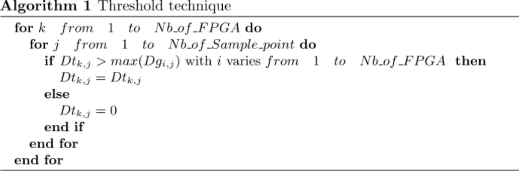
This approach comes from the observation in the Sec 4.1 :The difference of EM Measurement (in red) for AES with HT 1 (0.5%) is bigger than the fluctuation of process variations for certain places. Therefore it will be easier to detect HT if we choose specific points of interest. By using the threshold technique, we can select these points to improve the detection probability. For this second approach, we firstly calculate Dt and Dg as in previous section. After we apply the threshold technique for theses differences as the algorithm (1):
Algorithm 1 Threshold technique
for k f rom 1 to N b of F P GA do
for j f rom 1 to N b of Sample point do
if Dtk,j> max(Dgi,j) with i varies f rom 1 to N b of F P GA then
Dtk,j= Dtk,j else Dtk,j= 0 end if end for end for
The threshold is fixed automatically at each point of the trace using the golden traces. After apllying the threshold, we conserve only the interesting points which are the points around of clock edges in our case study. This is logical because all activity of AES is during the clock edges hence the contribution of HT is maximum at these points. And all uninteresting points will be put to zero. Next, we recalculate the sum of theses new differences using the formulas (7)(8) and also the false negative probability using the formula (3).
The result of threshold technique is presented in Table 2.
HT 1 (0.5%) HT 2 (1%) HT 3 (1.7%) 2nd approach 24% 0.017% 0.011%
Table 2: False negative detection probability with the Threshold technique.
We notice that the false negative probability of HT 0.5% is 24%. But the false negative probability of HT 1% and 1.7% are 0.017% and 0.011% thus they are easily detected. So this approach improved significantly the HT detection probability.
We also apply this approach for the mean of a 20 traces corresponding to 20 random plaintext of each implementation. The results for HT with size of 0.5% 1% and 1.7% are respectively 31% 0.19% and 0.59%. It is a bit worse than
the previous results using only 1 plaintext. But it could be helpful to detect sequential HTs which survey a set of plaintext.
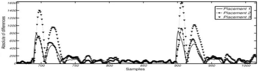
4.4 Impact of Hardware Trojan Placement
One drawback of the global EM measurement is that EM probe is very sensitive. The probe position will directly affect the result. So EM signals can also be different for a different placement of HT. In order to take into account this problem, we try to place the same HT in different positions and show its impacts on EM measurement. For this experiment, we place Trojan 3 in different places on the FPGA number 10 Appendix B. Firstly, HT is placed inside the AES core. Secondly, it is placed in the right-upper corner of FPGA. And lastly, we split Trojan 3 into 6 different parts and disperse them in the FPGA.
700 750 800 850 900 950 1000 0 200 400 600 800 1000 1200 1400 1600 Samples Absolute of differences Placement 1 Placement 2 Placement 3
Fig. 7: Impact on EM measurement for different locations of Trojan 1.7% on FPGA Virtex 5
Figure 7 gives the results of these experiments. Each curve shows the difference between the average of all AES infected circuit traces and the average of all AES genuine circuit traces. We noticed that EM measurement is practically the same for placement 1 and placement 2. For the placement 3 where HT was dispersed, the results are better. That is because of long routing lines which connect AES to HT and also power buffers used to supply the sub-set of FPGA where HT is located. In ASIC application, we could expect to see the same phenomenon because of long HT routing lines. Theses lines can have antenna effect hence amplify the EM leakage. For high-speed application, the long HT lines can create problem to HT working because of a big RC. Hence, attacker must insert additional buffers to ensure that HT work correctly with the same frequency than original circuit. Theses additional buffers will also amplify the EM leakage signal hence HT can be detected easily. So the placement and routing of HT have a little influence on the result performance.
5
Discussion
This paper show the probability of detecting a HT as a function of its size. We noticed the influence of process variations in our results. In our case study, the
HTs used are combinatorial in nature and we can easily detect them if its size is bigger than 1%. For a sequential HT, we estimate to have the similar results because sequential HT is difficult to activate but its contribution on SCA would be the same as combinatorial HT.
Our method does not take into account linear dependancies between sucessive points of side-channel traces. Therefore, it could lead to a bias in the gaussian distribution when summing these sucessive points. But it can be solved by summing only the local maximas detected from absolute of differences on geniune traces.
We also noticed that the trigger of HT is very big compared to its payload. Thus even if the HT is never activated, there is always the contribution of its trigger to the global consumption. Even if the size of the HT is as small as 1% of the actual AES circuit, its activity is bigger compared to the activity of AES at few time instants. For HTs, which connect directly to the critical paths (at the outputs of addroundkey in our case), the activity of HT trigger part could be important even if the payload of the HT is always inactive. In such cases, HTs using the “rare” nets (nets with a very small activity) to activate can reduce the detection probability.
This paper also gives the probability of detecting a HT with the size bigger than 1% compared to an AES circuit. The proportion of this HT will be smaller for a bigger complex circuit. But we can do a cartography on the circuit hence detect the HT by repeating the same procedure but only a selected zone of cartography. Regarding the impact of HT placement, we noticed that attacker must make the HT trigger as compact as possible. Also it is in the interest of the attacker to minimize the use of the routing lines to minimize the contribution of HT in the global or local activity in EM measurement. In any case, we were able to successfully detect a HT bigger than 1%, irrespective of its placement. Using EM measurement, we can select a local area where the HT is located hence increasing the contribution of HT which is not the case of global power measurement.
6
Conclusion and Perspectives
In this paper, we studied the detection of HT implementation on FPGAs, without changing the placement and routing of the original circuit. This represents a proof of concept study for ASIC circuit where HT are added by untrusted chip manufacturers before the final fabrication of the chip. First of all, we demonstrated the power of EM measurements in detection of HT by side-channel techniques. Next, we tested HT of different sizes to estimate the detection probability as a function of its size. We repeated our experiments on 10 different FPGA of the same reference (Xilinx LX30) to study the impact of process variations on this detection probability. The impact of placement of the HT is also studied, which has very little influence of the detection probability. We then introduce a novel metric to detect HT by exploiting side-channel techniques. This metric uses integration of the absolute difference of the captured traces. It predicts the
probability of HT detection with a determined false positive and false negative rates. Our results show that, using this metric, there is a probability superior than 99% with a false negative rate of 0.017% to detect a HT bigger than 1% of the original circuit.
Further extension of this work can include a more precise evaluation of impact of process variations on detection probability. This precision can be achieved by conducting the same experiments on n FPGAs, where n 10.
References
1. Miron Abramovici and Paul Bradley. Integrated circuit security: new threats and solutions. In Frederick T. Sheldon, Greg Peterson, Axel W. Krings, Robert K. Abercrombie, and Ali Mili, editors, CSIIRW, page 55. ACM, 2009.
2. Yousra M. Alkabani and Farinaz Koushanfar. Active hardware metering for intel-lectual property protection and security. In Proceedings of 16th USENIX Security Symposium on USENIX Security Symposium, SS’07, pages 20:1–20:16, Berkeley, CA, USA, 2007. USENIX Association.
3. M. Banga and M. S. Hsiao. ODETTE : A Non-Scan Design-for-Test Methodology for Trojan Detection in ICs. In International Workshop on Hardware-Oriented Security and Trust (HOST), IEEE, pages 18–23, 2011.
4. Shivam Bhasin, Jean-Luc Danger, Sylvain Guilley, Thuy Ngo, and Laurent Sauvage. Hardware Trojan Horses in Cryptographic IP Cores. In FDTC, pages 15–29, August 20 2013. Santa Barbara, CA, USA.
5. K.A. Bowman, S.G. Duvall, and J.D. Meindl. Impact of die-to-die and within-die parameter fluctuations on the maximum clock frequency distribution for gigascale integration. Solid-State Circuits, IEEE Journal of, 37(2):183–190, Feb 2002. 6. Byeongju Cha and S.K. Gupta. Efficient trojan detection via calibration of process
variations. In Test Symposium (ATS), 2012 IEEE 21st Asian, pages 355–361, Nov 2012.
7. Susmit Jha and Sumit Kumar Jha. Randomization Based Probabilistic Approach to Detect Trojan Circuits. In Proceedings of the 2008 11th IEEE High Assurance Systems Engineering Symposium, HASE ’08, pages 117–124, Washington, DC, USA, 2008. IEEE Computer Society.
8. Yier Jin, Nathan Kupp, and Yiorgos Makris. Experiences in hardware trojan design and implementation. In Proceedings of the 2009 IEEE International Workshop on Hardware-Oriented Security and Trust, HST ’09, pages 50–57, Washington, DC, USA, 2009. IEEE Computer Society.
9. Sebastian Kutzner, Axel Y. Poschmann, and Marc St¨ottinger. Hardware trojan design and detection: A practical evaluation. In Proceedings of the Workshop on Embedded Systems Security, WESS ’13, pages 1:1–1:9, New York, NY, USA, 2013. ACM.
10. Gilles Piret and Jean-Jacques Quisquater. A Differential Fault Attack Technique against SPN Structures, with Application to the AES and Khazad. In CHES, volume 2779 of LNCS, pages 77–88. Springer, September 2003. Cologne, Germany. 11. Miodrag Potkonjak, Ani Nahapetian, Michael Nelson, and Tammara Massey. Hard-ware trojan horse detection using gate-level characterization. In DAC, pages 688–693. ACM, 2009.
12. Reza Rad, Jim Plusquellic, and Mohammad Tehranipoor. Sensitivity analysis to hardware Trojans using power supply transient signals. In Proceedings of the 2008 IEEE International Workshop on Hardware-Oriented Security and Trust, HST ’08, pages 3–7, Washington, DC, USA, 2008. IEEE Computer Society.
13. Sergei Skorobogatov and Christopher Woods. Breakthrough silicon scanning discov-ers backdoor in military chip. In Proceedings of the 14th international conference on Cryptographic Hardware and Embedded Systems, CHES’12, pages 23–40, Berlin, Heidelberg, 2012. Springer-Verlag.
14. U.S. Department Of Defense. Defense science board task force on high perfor-mance microchip supply. http://www.acq.osd.mil/dsb/reports/2005-02-HPMS_ Report_Final.pdf.
A
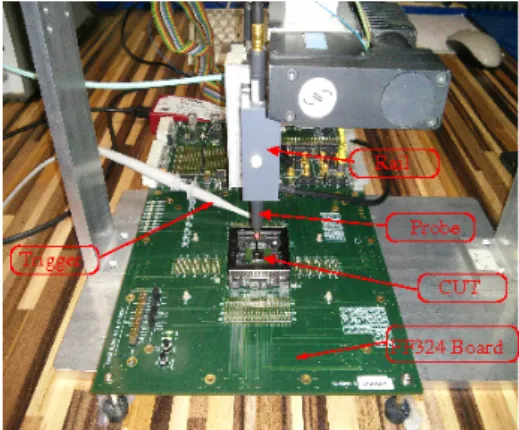
Measurement Setup
The measurement setup is shown in Figure 8. It is composed of:
• FF324 Virtex 5 experimental board with a ZIF socked that allows to change the device under test (DUT).
• Devices Under Test (DUT) are 10 Xilinx FPGA Virtex 5 (LX30) fabricated in 65 nm technology node.
• Langer RFU-5-2 probe that captures the global EM activity of the chip. • 30 dB Langer EMV power amplifier to amplify EM signal come from probe. • Agilent 54853A infiniium DSO configured at 5 GS/s.
• A 3-D cartography table, where the probe is attached, that can be controlled by the computer so that to minimize experimental variations.
• Agilent E3631A stabilised power supply for the test board.
This measurement platform ensure the same probe position for all FPGAs under test hence reduce the experimental variations. All measurement were realized with the same temperature condition. The acquisition were done by script via computer. The goal of the experiment is to detect any significant abnormal activity without being able to trigger the added HT. During the measurements, the HT is never activated. In our scenario, the designer knows the architecture and the characteristics of the DUT and is able to simulate the the behavior of the DUT. Each captured trace contains full activity of the cipher and the communication before and after the cipher. Once the traces are captured, we analyze them to select the interesting points that are used to detect any abnormal activity when a given node of the DUT is stimulated. The traces are acquired for random plaintexts, where each trace is averaged 1000 times by the oscilloscope to minimize the measurement noise. A plaintext which can activate HTs inserted is never used.
B
Hardware Trojan with Different Placements
HT with the size of 1.7% was placed in 3 different placements as Figure 9. EM probe was placed on the AES circuit. For each measurement, the position of EM probe is unchanged.
Fig. 8: Platform EM Measurement FPGA Virtex 5 LX30 AES circuit Placement 3 EM Probe Placement 1 Placement 2