Abstract—The current paper presents a structural assessment and proposals for retrofit of the National Youth Foundation Building, an existing reinforced concrete (RC) building in the city of Igoumenitsa, Greece. The building is scheduled to be renovated in order to create a Municipal Cultural Center. The bearing capacity and structural integrity have been investigated in relation to the provisions and requirements of the Greek Retrofitting Code (KAN.EPE.) and European Standards (Eurocodes). The capacity of the existing concrete structure that makes up the two central buildings in the complex (buildings II and IV) has been evaluated both in its present form and after including several proposed architectural interventions. The structural system consists of spatial frames of columns and beams that have been simulated using beam elements. Some RC elements of the buildings have been strengthened in the past by means of concrete jacketing and have had cracks sealed with epoxy injections. Static-nonlinear analysis (Pushover) has been used to assess the seismic performance of the two structures with regard to performance level B1 from KAN.EPE. Retrofitting scenarios are proposed for the two buildings, including type Λ steel bracings and placement of concrete shear walls in the transverse direction in order to achieve the design-specification deformation in each applicable situation, improve the seismic performance, and reduce the number of interventions required.
Keywords—Earthquake resistance, pushover analysis, reinforced concrete, retrofit, strengthening.
I. INTRODUCTION
HIS building complex was first designed according to the then-current design codes in 1972 as "Igoumenitsa Secondary School" (Fig. 1). It was constructed from RC between 1975 and 1978. The structure consists of four distinct and static independent buildings separated by construction joints: Buildings I, II, III, and IV. Buildings I, II, and III are arranged in the front of the complex, to the southwest. Buildings I and III are three stories tall and consist of pilotis plus two overlying floors. They are arranged symmetrically on either side of the central Building II, which is a three-story structure with a basement. The two upper floors A' and B' of these buildings communicate with each other via a corridor at the rear. These portions of the building complex have accommodated dormitories and administrative offices. Access to the relevant floors is provided via two symmetrically
C. Maraveas is with C. MARAVEAS & Associates P.C.-Consulting Engineers, Athens, Greece (corresponding author, phone: +30-2108223402; e-mail: c.maraveas@maraveas.gr) and also researches at the University of Liege, Belgium and the University of Leeds, UK.
G. G. Triantafyllou is with C. MARAVEAS & Associates P.C.-Consulting Engineers, Athens, Greece (e-mail: structures@maraveas.gr).
A. Plesias and K. Petronikolos are with Evergos SA – Consulting Engineers, Xanthi, Greece (e-mail: info@evergos.gr).
arranged spiral stairs from Building II. Building IV is located on the north side of the complex and consists of an elevated ground floor space with a mezzanine at the back and classrooms that are partially underground. The ground floor of the building was used as an event venue, while semi-basement halls were used as locations for reading. The building has symmetry around the axis perpendicular to those of buildings I, II, and III in the East–West direction (Fig. 2). The building complex plan is as follows: basement 140 m2, semi-basement 900 m2, ground floor 1200 m2, A' floor 600 m2, B' floor 600 m2, and soffit 600 m2. The building complex also includes a pillared entrance area, stairs, ramps, and a small entrance house.
A year after completing the construction of the building complex in 1979, the city and the wider area of Igoumenitsa experienced successive seismic events. The principal earthquake had a magnitude of 5.1 degrees on the Richter scale. The earthquake epicenter was located 5.6 km west of the city in the wider area of the harbor entrance and had a low focal depth of 10 km.
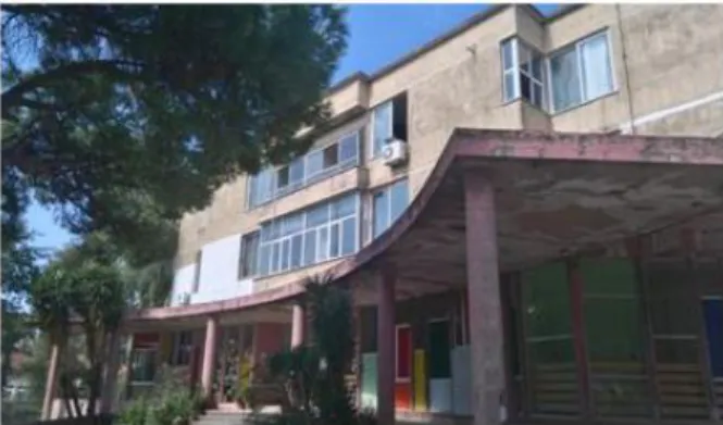
Fig. 1 The National Youth Foundation Building in Igoumenitsa, Greece
All buildings in the newly built complex suffered damage. Specifically: Building I presented:
Differential subsidence between columns, resulting in rotation and deformation of the building in relation to the central Building II.
Fractures in the cantilever slabs on the ground floor and the A' floor at support positions.
Cracking of the lower 10 cm-thick slab of the pilotis ceiling. It is noted that these slabs are of secondary use and act as insulating structural components.
Fracture of the shared foundation between Buildings I and II and of the corresponding column.
Chrysanthos Maraveas, Argiris Plesias, Garyfalia G. Triantafyllou, Konstantinos Petronikolos
Structural Analysis and Strengthening of the National
Youth Foundation Building in Igoumenitsa, Greece
T
Fig. 2 Overview of the building complex in Igoumenitsa, Greece Building II presented:
Cracking of a ground floor beam.
Vertical cracking of a concrete wall at its points of union with a column and another concrete wall, as well as at a symmetrical concrete wall.
A 45° crack in a concrete wall at the position where the curved and linear parts are connected.
Cracking due to flexure at the opening of a stairway. Building IV presented:
Cracking of the bottom of a folded concrete slab shell of the ceiling of the ground floor.
Cracking between the supports of beams and columns. Cracking between the supports of two basement ceiling
beams at a concrete wall.
Cracking at the opening of a beam.
Cracking of a ground floor ceiling slab around a column. Cracking of circular columns at the basement floor level. Some of this damage was repaired immediately after the earthquake. After drilling and testing the damaged areas, the following comments were recorded. In Buildings I, II, and III, the slabs and beams were generally under-reinforced, with low volumetric ratios of steel reinforcement. The live loads that were initially received were lower than expected. However, it was not thought necessary to strengthen the slabs and beams, as no damage was noted. A generalized deficiency was found in the x–x direction (East–West) of the concrete walls and columns, due to the very low rigidity of the concrete walls in the weak axis. In Building IV, deficiencies were observed in the reinforcement of the ground floor ceiling folded concrete slab shell beams. The cracks that developed during the earthquakes were attributed to this. It was not thought necessary to strengthen the basement ceiling slabs and beams. The initial structural analysis assumptions considered the perimeter columns as cantilevers. This structural system was not realistic. Damage to the bottom and top of the basement floor was attributed to this. Overloading was also observed in columns and concrete walls of the internal frames that bore the basement ceiling slabs, due to the uneven stiffness distributions in their longitudinal and transverse directions. The expected subsidence within, and the fracture strength of the building complex were found to be within the permissible limits.
In summary, the damage was attributed to:
The differing dynamic responses of the individual parts of
the building complex.
The non-uniformity of the load-bearing ground between the parts of the complex, particularly towards Building I, where absence and sudden slippage of the subsoil were problematic.
The low seismic energy absorption capacities of Buildings I and III.
The inadequacy of some cross-sections and their low steel reinforcement volumetric ratios.
Densification of the subsoil due to changes in its composition during the earthquakes.
The long duration of the principal earthquake.
The high flexibilities of the superstructures of Buildings I, III, and IV in their respective transverse directions. The following retrofitting measures were proposed: Strengthening the foundations of Buildings I and III by
applying micropiles to the column footings, strengthening the connecting beams, as well as the ground floor columns and beams, with concrete jacketing, and enhancing the stiffness of the A' and B' floors by constructing transverse concrete walls in positions of corresponding masonry walls at each story.
Enhancing the stiffness of the A' and B' floors of Building II by constructing four stiff concrete walls at each story, strengthening some beams and columns in the ground floor, and strengthening the ends of some concrete walls, as well as by sealing cracks with epoxy injections. Strengthening the initial circular columns and the
corresponding beams on them in Building IV and application of tensile tendons to the tops of the ground floor columns.
The building functioned for some years as a school that primarily used the semi-basement rooms of Building IV. Only Buildings II and IV were studied for the building complex upgrade needed to make it ready for use as a Municipal Cultural Center. The recommended interventions concern only these parts of the complex.
II. STRUCTURAL DETAILS AND DESCRIPTION
The main objectives of this study were to evaluate the structural adequacy and plan a retrofit of Buildings II and IV, as well as to perform a seismic assessment according to KAN.EPE [1]. In-situ, non-destructive and destructive tests were conducted to further assess the structural condition and details. The cover was removed in order to assess the reinforcement at selected column and beam locations. Locations from the initial construction phase and from the concrete jacketing intervention were accessed in order to verify reinforcement details, as shown in Figs. 3 (a) and (b). A sample excavation was performed to reveal the foundations in a column of Building IV, as presented in Fig. 3 (c). Areas with localized damage were also inspected, as shown in Figs. 3 (d) and (e).
(a) (b)
(c)
(d)
(e)
(f)
Fig. 3 Disclosure of steel reinforcement materials (a,b), disclosure of the foundation in a column (c), localized damage (d,e), and a
non-destructive test (f)
Laboratory tests were also conducted in order to verify the mechanical properties of the materials, as well as the configuration, type, and dimensions of steel reinforcement materials, and the concrete cover depth. A Schmidt hammer [Fig. 3 (f)] and a rebar detection device were also used for this purpose. The compressive strength of the concrete was estimated by testing concrete cores. The carbonation depth of the concrete was also measured. Half-cell potential measurements were conducted in steel bars in order to assess the probability of corrosion in the RC elements.
The experimental results from the non-destructive and destructive tests indicated that the compressive strength of the concrete varied with both the structural element and the time period of its incorporation into the structure. More specifically, the average compressive strengths of cube specimens from the floor slabs of A' and B' in Buildings I, II, and III were 24.60 MPa and 26.22 MPa, respectively. They exhibited standard deviations of 5.99 MPa and 4.50 MPa, respectively. The average compressive strength of concrete in the beams within Building II was 26.86 MPa. The concrete specimens from the folded concrete slab shell from the ground floor of Building IV presented an average compressive strength of 15.33 MPa and standard deviation of 4.31 MPa. The compressive strengths of the concrete jackets placed around columns and beams during the strengthening project were even lower. The average compressive strength of these cube specimens was 15.14 MPa, with a standard deviation of 3.19 MPa. This differentiation in compressive strength between the old and the new concrete was also confirmed via in-situ non-destructive tests with the Schmidt hammer in the relevant positions.
The configuration of the reinforcement materials was captured via local disclosure of steel rebar. Ribbed steel rebar of quality StIII with an average tensile strength fym = 460 MPa was identified in the main steel reinforcement. Smooth steel rebar of quality St I with an average tensile strength fym = 260 MPa was identified for the stirrups. Typically, the steel rebar in the supports for the Building IV slab (edge of beam) presented surface corrosion. In addition, significant moisture was noted on the surface of the concrete in the same positions. Corrosion activity was tested by measuring the half-cell potential of the steel reinforcement. The experimental results indicated that the probability of corrosion was over 90% for 54% of the surface of the soffit floor of Building I. The probabilities of corrosion were lower in the soffit slabs of Buildings II and III. Higher concrete carbonation depths were observed in the unprotected parts of the slab near the supports. The long period of abandonment and low-intensity use of the building complex had significant effects on its durability in the face of environmental factors. Despite the successful crack repairs, the ensuing lack of maintenance led to development of moisture, gradual corrosion of some elements, and detachment of the concrete cover. The corrosion half-cell potential measurements indicated further evolution of corrosion, leading to progressive degradation of the load-bearing capacity of the structure.
Building II was initially designed as a RC structure,
symmetrical along its North–South axis, as illustrated in Fig. 4. The common methodology of the era was followed, in which concrete slabs were used as surface elements to undertake the vertical actions on each service level of the structure. They carry the vertical loads through a system of beams and then through columns or concrete walls to the ground. The slabs had rectangular cross-sections. Structural meshes of standard dimensions were used a steel reinforcement. This type of reinforcement is unusual in Greek construction and experiences problems in corrosive environments. Corrosion activity in terms of the residual cross-sections of steel meshes is greater than when other strategies are used, due to the small diameter of the rebar employed (4–6 mm). The slabs were 15 cm-thick, which is considered sufficient for their intended purpose (usual length of 4 m). However, Building II contained slabs that often exceeded 6 m in length. Modern regulations indicate that this thickness is marginal for ensuring the required slenderness. The beams involved had small cross-sections and were reinforced with marginal quantities of steel. This often resulted in under-reinforced elements.
Fig. 4 Illustration of the structural layout of Building II Vertical elements (columns and concrete walls) were placed primarily to satisfy architectural requirements with regard to the arrangement of curved sections on the ground floor for the layout of the stairs. These curved walls were not founded on the ground, but rather were settled on curved beams. In addition, there were small columns on the external perimeter of the building (North–South) that act as point supports and mainly affect the static combinations of actions.
In summary, four strong North–South support lines were created by concrete shear walls on the upper two floors. One characteristic of the support lines was that they presented discontinuities on the ground floor, as their central part was not present. There was no stiffness on the upper floors in the transverse direction (East–West). This contrasted with the ground floor, where diagonally arranged and curved walls placed symmetrically on both sides of the central aisle created two strong pillars of stiffness. These pillars received the majority of the seismic energy from the earthquakes, resulting in significant damage. The selected retrofit measures mainly included the installation of strong shear walls along the East– West direction on the 1st and 2nd floors (four concrete
walls/level). Due to architectural constraints, these walls did not descend to the ground floor and were not founded. As a result, their contribution to the seismic response of the building was improved in terms of increasing the stiffness on the upper floors (reduced efficiency). In addition, not all columns or walls were strengthened as designed, particularly in the basement.
Building IV was first designed as a symmetrical RC structure with two symmetrically protruding parts at its eastern and western boundaries, as illustrated in Fig. 5. It is a two-story building with a balcony that acts as a "loft" and that is to be demolished. The layout varies from level to level. Concrete slabs were used as surface elements for transferring vertical actions on each service level of the structure. They carry vertical loads through a system of beams, followed by columns or concrete walls that go to the ground. The slabs have rectangular cross-sections. The slab of the event venue (with a length of approximately 13 m) was a folded concrete slab shell. It was assumed that the vertical elements of the folded concrete slab shell were the beams of the system and the horizontal parts were the small slabs. The behavior of the simulation after the earthquake proved the ineffectiveness of the latter. Structural meshes of the standard dimensions used in Building II had been used as steel reinforcement, producing the problem of cross-section loss in corrosive environments that is mentioned above. The slabs were 15 cm-thick, which is considered sufficient for usual length of 4 m, but for Building IV where slabs often exceeded 6 m in length, this thickness is marginal for ensuring the required slenderness. Beams were reinforced with marginal quantities of steel, which often resulted in under-reinforced elements.
The vertical element structural system consisted of two strong support lines at the floor level that carried the folded concrete slab shell. These support lines consisted of circular columns that behaved unacceptably during the earthquake, failing at their bottoms. These columns were strengthened with concrete jacketing to form an overall cross-section of 75 cm x 75 cm per column. On the ground floor, two additional support lines were constructed with a mixed system of vertical elements (columns and walls) and added to the existing strong columns. Thus, the structural system used to simulate the force imparted by the earthquake was composed of:
Two frames in the East–West direction within the story Two frames in the North–South direction within the story
(and two additional lateral frames)
Four frames in the East–West direction on the ground floor
multiple frames in the North–South direction on the ground floor
The retrofitting techniques of the initial study focused on the installation of strong North–South beams on the ground floor that strengthened the diaphragmatic function of this level even though the connection points with the existing beams did not ensure good function for the nodes. Tensile tendons were installed on the tops of the perimeter columns of the folded concrete slab shell of the ground floor ceiling. Columns were strengthened via concrete jacketing.
Fig. 5 Illustration of the structural layout of Building IV III. DESIGN PRINCIPLES
KAN.EPE. [1] specifications were used in order to perform the capacity assessment. The performance level of the structure for a specific level of seismic hazard was selected by the structural engineer. The structural assessment was performed based on a series of performance objectives. Retrofitting scenarios were proposed to correct any issues. Performance objectives were chosen to meet requirements for a specific hazard levels that were deemed essential. The performance levels from KAN.EPE [1] are determined as follows:
Operational: Overall damage is very light and does not hinder operation of the structure.
Life safety: The damage is repairable and does not endanger human life.
Collapse prevention: The damage is characterized as severe, but the structure can still carry vertical loads. The hazard levels related to seismic action are determined as follows:
Occasional earthquake hazard level: The probability of exceedance in 50 years is 50%, with a mean return period of 70 years.
Rare earthquake hazard level: The probability of exceedance in 50 years is 10%, with a mean return period of 475 years.
The proposed use according to the Building Sustainability Study clearly classifies the buildings as being within the SIII importance category. This category applies to buildings used for public gatherings, theaters, etc. For buildings of importance category SIII, the minimum tolerable performance or redesign objective is B1. This means that the structure must be prepared for seismic activity with a 10% probability of exceedance within the conventional lifespan of 50 years (return period for the seismic action 475 years). Such a structure would suffer significant and extensive but repairable damage, while the structural elements would retain residual strength and stiffness in order to carry the foreseen vertical loads. Such a structure could also withstand medium-intensity aftershocks.
Several Eurocode specifications were also used. They were EN 1990 [2] for the structural design basis, EN 1991-1-1 [3], EN 1991-1-3 [4] to determine the loads imposed on older structures, EN 1997-1 [5] for the geotechnical design and EN 1998-1 [6] for seismic analysis of the structures.
The following assumption was used in design checks:
d
d R
S (1)
where the design actions are equal to
)
(
k
f
S
S
S
d sd (2)and the resistances are equal to
)
/
(
)
/
1
(
rd k m dR
R
R
(3)The variables γf, γm are the safety factors for the actions and the materials, respectively. They are calculated in order to take into account possible adverse deviations of their respective variables. Sk refers to the representative values of the permanent and accidental actions for exceedance once every 50 years.
In addition to the self-weight of Building II, distributed dead loads of 1.0 kN/m2 and 1.5 kN/m2 were applied to the interior floors and for the ground floor, respectively, while 2.0 kN/m2 was assumed for the coatings of the soffit. The loads on the interior and perimeter walls were 2.1 kN/m2 and 2.8 kN/m2, respectively. The floor live load was 2.0 kN/m2 for the story floors (Category B offices), 3.5 kN/m2 for the stairs, 5.0 kN/m2 for the gathering places (Category C3) and 0.5 kN/m2 for the soffit (Category H, less favorable than snow loads).
In addition to the self-weight of Building IV, distributed dead loads of 1.5 kN/m2 and 2.0 kN/m2 were considered for the interior floors with lightweight platforms and electromechanical equipment respectively, while 1.0 kN/m2 was used for the coatings of the soffit. The load on the perimeter walls was 2.8 kN/m2. The floor live load was 4.0 kN/m2 for the gathering places (Category C2) and 0.5 kN/m2 for the soffit (Category H, less favorable than snow loads).
Earthquake action was determined via the response spectrum given in EN1998-1 [6], which was obtained for soil type C and soil factor S=1.15. The design ground acceleration was equal to ag=0.24g and the importance factor was γΙ=1.2.
The combinations of actions for both the ultimate limit state (ULS, main and random combinations) and the serviceability limit state (SLS) were determined in accordance with current regulations. The corresponding action coefficients were taken from KAN.EPE. [1] based on the reliability level and the corresponding combination coefficients of the variable actions ψi. Safety checks for seismic combinations should be performed in terms of displacements. Thus, the material properties are typically represented by their mean values. When checks are performed in terms of forces, the properties of the materials are represented by their mean values minus a standard deviation, and the safety factors γc and γs are used based on the relevant reliability level, as defined in KAN.EPE. [1].
The anticipated simulation uncertainties are considered by applying the corresponding safety factors γSd and γRd. Since these buildings were noted as having light and local damage
or/and being subject to retrofit and strengthening actions, a simulation coefficient γSd=1.10 is obtained. Furthermore, in order to carry out the elastic analysis and perform the preliminary evaluation check, the coefficient is increased by 0.15 such that γSd=1.25.
Based on the classification of the reliability level of the geometric data (satisfactory), the coefficients for the permanent actions are taken to be γg=1.20 for the main combinations and γg=1.00 for other combinations (random seismic combinations) at ULS.
From the classification of the reliability level of the data (satisfactory), the coefficients of the materials at ULS are taken to be γc=1.30 and γs=1.15 for the concrete and steel, respectively, based on current regulations.
In performance-based design, all design criteria are tied to specific performance objectives. The structural performance of an existing building in KAN.EPE. [1] is assessed with reference to the performance objectives and a retrofit scenario is proposed. The aim is to ensure that the capacities of the structural elements exceed the demands of seismic excitation. Since the desired performance level, reliability of the geometric details, materials, and their properties have been determined and damage to the present state of the structure has been evaluated, the geometry and reinforcement of the structure can be simulated accurately. The interaction and moment–curvature curves for beams and columns were calculated. An elastic dynamic analysis was initially executed using the elastic spectrum without safety factors and by increasing the simulation coefficient γSd by 0.15. This was done to investigate whether the KAN.EPE. [1] criteria are satisfied so that we could apply elastic (static or dynamic) analyses to the evaluation and redesign of the structure. The deficiency factors λ=S/Rm that indicate the resistance to an earthquake are calculated for each element, where S is the moment due to actions of the combination of seismic forces and Rm is the corresponding resistance of the element based on the mean material strengths. The λ factors are calculated for each primary element. The largest value calculated for an individual element on a floor (the most overstressed) is considered the critical factor λ for the floor. The morphological regularity of the building is also examined.
The preliminary analysis is conducted first in order to calculate the criteria to be used to select the type of the analysis and indicate the building regularity and earthquake resistance. If λ>4 for more than 30% of the building elements, further evaluation is meaningless. If the preliminary check indicates that an inelastic static analysis should be applied, it is necessary to confirm that the influence of the higher eigenmodes is not significant. Based on a dynamic elastic analysis, the seismic shear force is calculated at each floor and seismic direction for those eigenmodes that activate at least the 90% of the building mass and for the fundamental (per direction) eigenmode. The influence is deemed significant when the ratio of the shear force from the many eigenmodes (Vall) to the shear force from one eigenmode (V1) is greater than 1.3, even if this occurs only in one direction and on one floor. If this applies even to a level and to one direction, an
inelastic static analysis (pushover) should be applied, but only in conjunction with an elastic dynamic analysis that considers the unfavorable results of the two analyses. Pushover analysis has been widely used in the seismic assessment of structures. It is used to estimate the structural capacities of the existing and retrofitted structures upon being subjected to various earthquake loads [7], [8].
The goal of inelastic static analysis (pushover) is to evaluate the inelastic deformations of the structural elements under seismic action. These inelastic deformations are compared to the permissible values associated with the target performance level. The inelastic load–deformation relationships of individual structural elements are considered. The model is then subjected to horizontal loads distributed in proportion to the inertial forces of the earthquake. These loads increase monotonically until a structural element is unable to carry its vertical loads. At each step of the analysis, the base shear (the sum of the horizontal loads) and the displacement of a characteristic point of the examined structure (control node) that is generally taken at its peak, are recorded. The base shear-peak displacement curve named as a resistance curve is then plotted. The primary resistance curve is idealized as a bi-linear curve that is assumed to correspond to the load– displacement curve of an equivalent single degree of freedom (SDOF) system, the response of which is correlated with the response of the structure. The design earthquake displaces the control node (target displacement). The relevant displacement is calculated using the elastic design spectrum by applying the method of displacement modification. The target displacement is derived from the elastic displacement of the equivalent single degree of freedom (SDOF) system, which is multiplied by a series of correction coefficients to consider certain factors such as its difference from the peak displacement of the structure, the elastic/inelastic displacement difference, strength and stiffness degradation due to cyclic loading, and the influences of P-Delta effects. The final step of the inelastic static analysis is to check the performance criteria by comparing the available strengths of the cross-sections to the required response values that allow the control node to experience the target displacement. Tests are performed in terms of internal forces for brittle failure and in terms of displacement or deformation for ductile failure modes. In the latter case, the acceptance criteria are expressed as available plastic displacement rates or deformation, depending on the desired structure performance level. The analysis of Buildings II and IV was performed according to the above-mentioned procedure using SCADA Pro v17 by ACE-HELLAS [9].
IV. STRUCTURAL EVALUATION OF THE EXISTING BUILDINGS For Building II, the results from the preliminary elastic static analysis adequacy indicated significant exceedance, expressed as the percentage by which the deficiency factor limits (λ>2.5). The results indicate that 42% of the main structural elements (columns, concrete walls, and beams) failed. Specifically, 61% of the vertical elements and 33% of the beams failed. Furthermore, tests of the differences between the masses and stiffnesses of various levels in the building, the
average relative displacement between the nodes of the floor, the average relative displacement at x floors, the average relative displacement at z floors and the morphological regularity of the building were not satisfied. However, the criterion that references the upper limits of the building eigenperiods was satisfied. Based on these results, the only feasible method of further evaluation was the inelastic static method (pushover). Pushover analysis confirmed the results of the preliminary test with regard to the inability of the building to withstand seismic deformation at the selected performance level (B1). For at least one load combination, the building was unable to reach the design displacement limit and collapsed as mechanism. This case concerns triangular load distribution of the seismic combination Fx+0.3Fz. As can be seen in Fig. 6, the building is unable to reach the target displacement.
Fig. 6 Force–displacement curve of Building II for a triangular load distribution of the seismic combination Fx+0.3Fz
The main direction of the earthquake changes the requirements for retrofitting and strengthening of the vertical elements significantly. It is obvious that the overall stiffness in the transverse x direction (East–West) is reduced due to the formation of the structure (thin, elongated North–South concrete walls). In summary, Building II required structural strengthening measures in each case, as the structure could not carry the seismic load and meet the minimum requirements for performance level B1.
For Building IV, the results from the preliminary elastic static analysis check indicated significant exceedance, expressed as the percentage by which the deficiency factor limits (λ > 2.5) are exceeded. The results indicate that 44% of the main structural elements (columns, concrete walls, and beams) failed. Specifically, 77% of the vertical elements and 23% of the beams failed. Furthermore, tests of the differences between the masses and stiffnesses of the various levels in the building, the average relative displacement at x floors, the average relative displacement at z floors and the morphological regularity of the building were not satisfied. However, the average relative displacement between the nodes of the floor and the criterion that references the upper limits of the building eigenperiods were satisfied. Based on these results, the only feasible method of further evaluation was the inelastic static method (pushover). Pushover analysis
confirmed the significant number of plastic hinge positions and hence the retrofit requirement identified by the preliminary analysis The results indicate that the direction of the earthquake does not affect the retrofits that are required. In conclusion, Building IV exhibited damage to several structural elements. Retrofitting and strengthening are thus required. The locations where strengthening is required include existing strengthened elements, including beams. This introduces additional difficulties. The force-displacement curve of Building IV for a triangular load distribution of the seismic combination Fx+0.3 Fz is illustrated in Fig. 7.
Fig. 7 Force-displacement curve of Building IV for a triangular load distribution of the seismic combination Fx+0.3Fz V. STRENGTHENING PROPOSAL FOR THE EXISTING BUILDINGS
Based on the results from the analysis and the global response of existing Buildings II and IV to the applied loads, strengthening measures intended to enhance their performance have been proposed. Due to the significant number of failures, the need to investigate alternative scenarios in order to minimize failure positions economically has been considered. Point interventions and the addition of structural elements and systems are feasible at every level. Point interventions in an existing structure are not desirable as they can be expensive. Multiple combinations were calculated to find the optimum strengthening scenario (minimally-invasive options) for the two buildings, as the additional structural elements also require changes to the architectural characteristics of the building.
It was not considered appropriate to insert concrete wall elements in the multi-story portion of Building II. This intervention, which removes the flat area on the ground floor, would have changed the character and use of the structure. The retrofitting-strengthening scenarios that were considered as ways of enhancing the bending resistance included the following:
a) Type Λ steel braces on three floors and two spans on either side of the center.
b) Type Λ steel braces on three floors and three spans including the central one.
c) Type Λ steel braces on three floors and two spans on
0.0 340.7 681.4 1,022.1 1,362.8 1,703.5 0.000 0.025 0.050 0.075 0.100 0.125 V (k N)
d (m)
0 777,1 1554,2 2331,3 3108,4 3885,5 0,000 0,060 0,120 0,180 0,240 0,300 V (kN) d (m)either side of the center, addition of metal beams that connect to the ceiling in the middle span at all three floors, and addition of smaller type Λ steel braces to the ground floor in the transverse direction to restore wall continuity.
The analytical results indicate that solution c) is the most efficient, as it lets the building achieve the design displacement for each load combination, the global response is improved, and point interventions are reduced. The retrofitting scenario proposed for Building II is shown in Fig. 8.
Fig. 8 Building II strengthening proposal with type X steel braces for modeling purposes. The type Λ steel braces allow the access under
them
For Building IV, additional alternative strengthening scenarios were studied in order to reduce the number of point interventions required by the large extent of exceedance. Additional structural stiffness elements were examined to create a seismic load transfer mechanism in positions and directions in which the initial or/and strengthened structure exhibited deficiencies. The retrofitting-strengthening scenarios that were examined to enhance the bending resistance included the following:
a) Concrete walls in the transverse direction at four panels, including both extremes.
b) Concrete walls in the transverse direction at four panels, including both extremes and type Λ steel braces on two floors in the middle panel, arranged in the longitudinal direction of the building.
c) Concrete walls in the transverse direction at three panels including both extremes, a metal steel brace in the basement in the transverse direction to replace the concrete stiffness wall for accessibility reasons, type Λ steel braces on two floors in the middle panel in the longitudinal direction of the building, and type Λ steel braces in the basement to unload the concrete walls of the middle longitudinal frames of the building.
The analytical results indicate that solution c) is the most efficient, as it provides better building performance. The number of point interventions is reduced and most importantly, retrofitting of members that were previously strengthened via concrete jacketing is avoided. A presentation
of the retrofitting scenario proposed for Building IV is shown in Fig. 9.
A financial analysis of the strengthening scenarios is presented. The following financial estimation disregard the cost of non-structural restorations. In order to compare the costs of the proposed structural interventions, the quantities of concrete required for the construction of concrete jacketing and the cost of the structure including the required steel reinforcement were calculated in a uniform manner. All individual tasks (surface cleaning, preparation, opening holes for steel reinforcement, use of anchoring resins, etc.), as well as the construction of the structural systems of type Λ steel braces were taken into account. The restoration cost included works to improve the durability of the structure too.
Fig. 9 Building IV strengthening proposal with type X steel braces for modeling purposes
For Building II, the plan is to strengthen the slabs with shotcrete concrete with embedded steel reinforcement and to strengthen beams and ground floor concrete walls via concrete jacketing. The reinforcement design also calls for construction of an entrance ramp and demolition of the canopy roof and stairs. Furthermore, the corroded concrete surfaces are to be repaired by applying anti-corrosion measures. The structural interventions for the construction of the new frame elements to be inserted between the RC elements include type Λ or K steel braces that consist of horizontal and vertical elements, as well as diagonal configuration links of the desired morphology. The total cost of restoring and strengthening Building II is thus estimated to be approximately 450.000€.
The retrofit plan for Building IV includes strengthening the slabs with shotcrete concrete, demolishing concrete surfaces, and repairing corroded concrete surfaces by applying anti-corrosion measures. Two scenarios are proposed for strengthening of the beams and concrete walls. The first includes construction of concrete jacketing for both beams and concrete walls, while the second includes concrete jacketing for beams and construction of new metal frames and concrete elements. The total cost of restoring and strengthening Building IV following the first scenario is estimated to be approximately 200.000€, whereas the cost of the second scenario is estimated to be approximately 210.000€.
In summary, reducing the incorporation of new elements increases the amount of concrete jacketing required. It is therefore recommended that for Building II all of the proposed metal frames be constructed with type Λ or K bracings. For Building IV, the estimated costs of the two scenarios differ by only 10%. The second scenario is recommended for the purpose of design uniformity and due to the difficulty of strengthening previously strengthened members.
VI. CONCLUSION
This paper presents the seismic assessment and retrofit of the National Youth Foundation Building in the city of Igoumenitsa, Greece. Inelastic static analysis (pushover) was used to assess the seismic integrities of Buildings II and IV for performance level B1 as defined by the Greek Retrofitting Code (KAN.EPE.). The building complex was affected by the 1979 earthquakes and damaged in several places. Some RC elements have already been strengthened via concrete jacketing and had cracks sealed using epoxy injections. Retrofitting and strengthening scenarios including type Λ steel braces and transverse concrete walls are proposed for the two buildings. Analyses showed that the strengthening proposal is effective in enhancing the seismic performances of the two buildings, causing them to present an improved response to seismic loading.
REFERENCES
[1] Greek Retrofitting Code (KAN.EPE.). Second version. Organization of Seismic Protection, Athens, Greece, 2017 (in Greek).
[2] European Committee for Standardization. Eurocode: basis of structural design. Brussels, Belgium: European Standard EN 1990; 2002. [3] European Committee for Standardization. Eurocode 1: actions on
structures-Part 1-1: general actions-Densities, self-weights, imposed loads for buildings. Brussels, Belgium: European Standard EN 1991-1-1; 2002.
[4] European Committee for Standardization. Eurocode 1: actions on structures-Part 1-3: general actions-Snow loads. Brussels, Belgium: European Standard EN 1991-1-3; 2005.
[5] European Committee for Standardization. Eurocode 7: geotechnical design-Part 1: general rules. Brussels, Belgium: European Standard EN 1991-7; 2005.
[6] European Committee for Standardization. Eurocode 8: design of structures for earthquake resistance-Part 1: general rules, seismic actions and rules for buildings. Brussels, Belgium: European Standard EN 1998-1; 2004.
[7] C. C Mitropoulou, N. D. Lagaros, M. Papadrakakis, “Life-cycle cost assessment of optimally designed reinforced concrete buildings under seismic actions,” Reliability Engineering and System Safety, vol. 96, 2011, pp:1311-1331.
[8] N. D. Lagaros, C. C. Mitropoulou, “The effect of uncertainties in seismic loss estimation of steel and reinforced concrete composite buildings,” Structure and Infrastructure Engineering, vol. 9, no. 6, 2013, pp:546-566.
[9] SCADA Pro v17 Structural Analysis & Design by ACE-HELLAS, Athens, Greece.