HAL Id: tel-01220655
https://tel.archives-ouvertes.fr/tel-01220655
Submitted on 3 Dec 2015HAL is a multi-disciplinary open access
archive for the deposit and dissemination of sci-entific research documents, whether they are pub-lished or not. The documents may come from teaching and research institutions in France or abroad, or from public or private research centers.
L’archive ouverte pluridisciplinaire HAL, est destinée au dépôt et à la diffusion de documents scientifiques de niveau recherche, publiés ou non, émanant des établissements d’enseignement et de recherche français ou étrangers, des laboratoires publics ou privés.
Analysis in Vehicular Network
Naila Bouchemal
To cite this version:
Naila Bouchemal. Quality of Service Provisioning and Performance Analysis in Vehicular Network. Networking and Internet Architecture [cs.NI]. Université de Versailles-Saint Quentin en Yvelines, 2015. English. �NNT : 2015VERS029V�. �tel-01220655�
Pr´esent´ee `a
Universit´e de Versailles Saint Quentin en Yveline Pour obtenir le grade de
DOCTEUR de l’Universit´e de Versailles Mention Informatique
par
Naila BOUCHEMAL
Quality of Service Provisioning and Performance Analysis in Vehicular Network
Soutenue 25 Juin 2015 devant la Commission d’Examen :
Directeur de These:
Samir Tohme, Professeur des Universit´es, UVSQ. Co-encadrante:
Rola Naja, Maitre de conf´erences, UVSQ. Rapporteurs:
Michel Marot, Professeur HDR, T´el´ecom SudParis. Andr´e-luc Beylot, Professeur des Universit´es, Universit´e de Toulouse. Examinateurs:
Alain Bui, Professeur des Universit´es, UVSQ.
Jean-Marc Blosseville, Directeur de recherche HDR, IFSTTAR de Versailles. Merouane Debbah, Professeur des Universit´es, HUAWE.
V´eronique V´eque, Professeur des Universit´es, Universit´e d’Orsay. Invit´e:
Remerciements
To my parents
Contents
1 Motivation 1
1.1 Motivation . . . 1
1.2 Context of the Thesis . . . 3
1.3 Thesis Contributions . . . 4
1.4 Organization of the Thesis . . . 5
2 Vanet Architecture and Overview 7 2.1 Introduction . . . 7
2.2 Vehicular Communications V2I/V2V . . . 7
2.2.1 Vehicle to Vehicle Communications . . . 8
2.2.2 Vehicle to Infrastructure Communications . . . 8
2.2.3 Routing Based Communications . . . 9
2.3 Vehicular Networks Characteristics . . . 9
2.4 Description of The Functional Entities . . . 10
2.4.1 Basic Service Set (BSS) . . . 10
2.4.2 WAVE Basic Service Set (WBSS) . . . 11
2.4.3 Access Point (AP) . . . 11
2.4.4 Distribution System (DS) . . . 11
2.4.5 Extended Service Set (ESS) . . . 11
2.5 Available Standards and Protocols . . . 11
2.5.1 European Telecommunications Standards Institute (ETSI) Archi-tecture . . . 11
2.5.2 Communication Access for Land Mobiles (CALM ) Architecture . . 12
2.5.3 Wireless Access for Vehicular Environment (WAVE) Architecture . . 13
2.6 Conclusion . . . 23 iii
3 LTE Architecture and Overview 25
3.1 Introduction . . . 25
3.2 LTE Architecture . . . 25
3.3 Quality of Service (QoS) . . . 27
3.3.1 The Bearer . . . 27
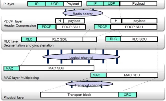
3.4 Interactions Between Layers . . . 29
3.4.1 The Physical Layer . . . 31
3.4.2 The Medium Access Control Layer (MAC) . . . 33
3.5 MAC layer: Logical Channel Prioritization (LCP) Procedure Overview . . . 35
3.5.1 The Radio Link Control Layer (RLC) . . . 36
3.6 Conclusion . . . 36
4 Vehicular Applications 37 4.1 Introduction . . . 37
4.2 Vehicular Applications . . . 38
4.2.1 Safety Category . . . 38
4.2.2 Traffic Management Category . . . 40
4.2.3 Comfort Category . . . 41
4.3 Co-Drive project Vehicular Applications . . . 42
4.3.1 Service 1: Warning to a Foggy Zone Service . . . 43
4.3.2 Service 2: Inter-distance Measurement Service . . . 44
4.3.3 Service 3: Road Warning Event . . . 44
4.4 SOAPS Project Vehicular Applications . . . 45
4.4.1 Voice Source Modeling . . . 45
4.4.2 Video Modeling . . . 48
4.4.3 Web Browsing (HTTP) Source Traffic Model . . . 51
4.5 Conclusion . . . 53
5 Traffic Modeling and Performance Evaluation in V2I 802.11p Network 55 5.1 Introduction . . . 55
5.2 Literature Survey on Quality of Service . . . 56
5.3 Performance Modeling . . . 57
5.3.1 Facilities and Network Layer Modeling: Large-scale . . . 58
5.4 Performance Evaluation . . . 61
5.4.1 Simulation Scenario . . . 61
5.4.2 Simulation and Analytic Measurements . . . 61
5.5 Conclusion . . . 63
6 EDCA Virtual Collision Performance Evaluation and Mobility Modeling 65 6.1 Introduction . . . 65
6.2 Related Work . . . 67
6.3 Virtual Collision Mathematical Modeling . . . 68
6.3.1 Model Analysis . . . 71 6.4 Mobility Modeling . . . 72 6.5 Performance Parameters . . . 73 6.5.1 Throughput Calculation . . . 73 6.5.2 Delay Calculation . . . 74 6.6 Performance Evaluation . . . 76 6.6.1 Scenario Description . . . 76 6.7 Performance Analysis . . . 77 6.8 Conclusion . . . 80
7 MAC-LTE Scheduler Modeling and Performance Evaluation in LTE Net-work 81 7.1 Introduction and Related Work . . . 81
7.2 Applications Mapping and Source Traffic Modeling . . . 82
7.3 System Model . . . 83 7.3.1 Waiting in Queues . . . 84 7.3.2 Stationarity . . . 84 7.3.3 Analytical Resoluion . . . 84 7.3.4 Numerical Model . . . 87 7.4 Performance Evaluation . . . 87
7.4.1 Simulation and Numeric Measurements . . . 88
7.5 Conclusion . . . 92
8 Cross-Layer Scheduling Algorithm in LTE Multiservice Networks 95 8.1 Introduction and Related Work . . . 95
8.3 Cross Layer Scheduling Algorithm . . . 98
8.3.1 Dynamic Priority . . . 98
8.3.2 Cross Layer Interaction and Resource Allocation . . . 99
8.3.3 Cross Layer Interaction . . . 100
8.4 Performance Evaluation . . . 102
8.5 Conclusion . . . 105 9 General Conclusion and Future Directions 107 10 Publications, Presentation and Projects Reports 111
Summary
Road traffic crashes are one of the world’s largest public health and injury problems. Therefore road security has always been the main concern of transportation security stake-holders. During the last decades, public authorities and automotive companies have been involved in the safety improvement of our transportation systems by reducing the conse-quences of imminent accidents and decreasing the number of road injuries. Nevertheless, most of these preventive measures can only provide passive safety since they focus on the post collision phase. In fact, materials of energy absorption like airbags reduce the impact of an accident but do not prevent it.
This recognition of the inadequacy of these passive measures has oriented industrials to new and innovative perspectives that seek to avoid accidents and detect dangers in ad-vance rather than minimize the damage. In fact, according to relevant studies, 60pers of accidents can be avoided if the driver had been alerted half a second before the colli-sion. Drastic steps are already taken by automobile manufacturers to offer to drivers a larger telematics horizon and therefore enhance their range of awareness. If a collision is inevitable, active safety technology can proactively prepare the vehicle for the impact to reduce injuries. For example, vehicles’ sensors are employed to measure and assess a ve-hicle’s condition and environment, enabling the issuance of early warnings to drivers. On the other hand, a remarkable and similar step in that direction is achieved by networking research community using vehicular networks within Intelligent Transportation Systems (ITS). Vehicular networking is the enabling technology which allows the realization of the variety of applications and use cases. Given the significant potential to cater for diverse applications and their performance requirements, there has been a growing demand to equip vehicles with multiple connectivity modalities. In order to fully exploit these ca-pabilities, vehicles are required to intelligently select the most appropriate technology for the specific networking scenarios.
Vehicular communications offer great potential for increasing road safety and driver aware-ness. Nevertheless, benefits are not restricted to safety standpoint but span to further horizons making use of various cooperating technologies. In fact, vehicular applications can be divided into three categories: safety, traffic management and infotainment
tions. Safety applications could be event driven messages, and should have higher priority than periodic and comfort messages. Thus, service differentiation mechanisms and admis-sion control are needed. These mechanisms are applied at MAC layer. Therefore at a first step, the research and industry community standardized a standard for MAC layer in Vehicular Adhoc networks (VANETs).
Currently, two types of communication services are considered: narrowband services and broadband services respectively, carried by IEEE 802.11p technology for narrowband ser-vices and LTE for broadband serser-vices. Narrowband serser-vices cover both the serser-vices strict temporal requirement and the data exchange with elastic time constraints for driving assis-tance. Broadband services are provided for the high-speed information transmission while meeting more or less strict time constraints. Our thesis tackles the performance analysis, design and optimization of resource allocation mechanisms in broadband and narrowband networks.
R´
esum´
e
Les accidents de la circulation sont un des plus grands probl`emes de sˆuret´e publique. Par cons´equent la s´ecurit´e routi`ere a toujours ´et´e la principale pr´eoccupation des acteurs de la s´ecurit´e des transports. Durant les derni`eres d´ecennies, les pouvoirs publics et les en-treprises du secteur automobile ont ´et´e impliqu´es dans l’am´elioration de la s´ecurit´e de nos syst`emes de transport en r´eduisant les cons´equences des accidents imminents et en dimin-uant le nombre d’accidents de la route. N´eanmoins, la plupart de ces mesures pr´eventives ne peut assurer que la s´ecurit´e passive, car ils se concentrent sur la phase post collision. En fait, les ´equipements comme les airbags r´e´eduisent l’impact d’un accident, mais ne l’empˆechent pas.
Cette reconnaissance de l’insuffisance de ces mesures passives a orient´e les perspectives industrielles nouvelles et innovantes qui cherchent `a ´eviter les accidents et d´etecter les dangers `a l’avance au lieu de minimiser les dommages. En fait, selon des ´etudes perti-nentes, 60pers des accidents pouvaient ˆetre ´evit´es si le conducteur avait ´et´e alert´e une demi-seconde avant la collision. Des mesures drastiques sont d´ej`a prises par les con-structeurs automobiles afin d’offrir aux conducteurs une t´el´ematique plus large et donc d’am´eliorer leur gamme de sensibilisation. Si une collision est in´evitable, la technologie de s´ecurit´e active peut pr´eparer de mani`ere proactive le v´ehicule pour l’impact est r´eduire les dommages. Par exemple, les capteurs de v´ehicules sont utilis´es pour mesurer et ´eval-uer l’´etat de l’environnement d’un v´ehicule, permettant l’´emission d’alertes pr´ecoces aux conducteurs. D’autre part, une ´etape remarquable dans cette direction est obtenue par la mise en oeuvre des r´eseaux de v´ehicules dans les syst`emes de transport intelligents. La technologie des r´eseaux v´ehiculaires, permet la r´ealisation d’une vari´et´e d’applications. Compte tenu de l’important potentiel pour r´epondre `a diverses applications et leurs exi-gences de performance, il y a eu une demande croissante pour ´equiper les v´ehicules avec de multiples modalit´es de connectivit´e.
Afin d’exploiter pleinement ces capacit´es, les v´ehicules sont tenus de choisir intelligemment la technologie la plus appropri´ee pour les sc´enarios de r´eseaux sp´ecifiques. Les communi-cations entre v´ehicules offrent un grand potentiel pour accroˆıtre la s´ecurit´e routi`ere et la sensibilisation des conducteurs.
N´eanmoins, les avantages ne sont pas limit´es `a un point de vue de s´ecurit´e, mais `a d’autres xi
horizons de diverses technologies coop´erantes. En effet, les applications v´ehiculaire peu-vent ˆetre divis´ees en trois cat´egories: les applications de s´ecurit´e, de gestion du trafic et des applications d’info divertissement qui pourraient ˆetre entraˆın´es suite `a des messages d’´ev´enement, et devraient avoir une priorit´e plus ´elev´ee que les messages p´eriodiques et de confort. Ainsi, les m´ecanismes de diff´erenciation de service sont n´ecessaires. Ces m´e-canismes sont appliqu´es `a la couche MAC. Par cons´equent, dans une premi`ere ´etape, le milieu de la recherche et de l’industrie normalisent une norme pour la couche MAC dans les r´eseaux v´ehiculaires.
Actuellement, deux types de services de communication sont pris en compte: les services `a bande ´etroite et les services `a large bande, respectivement port´es par la technologie IEEE 802.11p pour les services `a bande ´etroite et LTE pour les services `a large bande. Les services `a bande ´etroite couvrent `a la fois la condition temporelle stricte et l’´echange des donn´ees avec des contraintes de temps ´elastiques. Les services `a large bande sont pr´evus pour la transmission de l’information `a haute vitesse dans le respect des contraintes de temps plus ou moins strictes.
Notre th`ese aborde l’analyse des performances, la conception et l’optimisation des m´ecan-ismes d’allocation des ressources dans les r´eseaux `a large bande et `a bande ´e´etroite.
List of Figures
1.1 CoDrive Architecture . . . 3 2.1 Functional entities [1] . . . 10 2.2 Architecture ETSI [2] . . . 12 2.3 Architecture CALM [3] . . . 13 2.4 WAVE Architecture . . . 14 2.5 Facilities Layer [39] . . . 15 2.6 MAC Layer [1] . . . 17 2.7 Mechanism DCF [1] . . . 18 2.8 Mechanism DCF with RTS/CTS [1] . . . 192.9 Mapping of user priorities to the access categories [1] . . . 20
2.10 WAVE standard channels [4] . . . 22
2.11 European standard channels allocation . . . 23
3.1 Overview of the EPC/LTE architecture [5] . . . 26
3.2 Types of Bearers [5] . . . 27
3.3 Protocol Layers . . . 29
3.4 User Plane . . . 30
3.5 Control Plane . . . 30
3.6 Type 1 LTE Frame Structure [6] . . . 31
3.7 Type 2 LTE Frame Structure [6] . . . 32
3.8 Resource block LTE Structure [6] . . . 33
3.9 MAC PDU stucture [7] . . . 34
3.10 LCP procedure [7] . . . 35
4.1 Vehicular applications classification. . . 38 xiii
4.2 Warning service . . . 43
4.3 Inter-distance Measurement service . . . 44
4.4 Road warning service . . . 45
4.5 2-state voice activity Markov model . . . 46
4.6 Typical Phone conversation Profile . . . 46
4.7 Example of generated Voice Traffic . . . 47
4.8 Example queuing analysis for ON/OFF models . . . 47
4.9 Operation of MPEG-4 . . . 48
4.10 Basic structure of an elementary packet . . . 49
4.11 Group of Pictures (GOP): IBBPBBPBBI . . . 49
4.12 Video MMPP model . . . 50
4.13 Packet Trace of a Typical Web Browsing Session . . . 51
4.14 Contents in a Packet Call . . . 52
5.1 Vehicular protocol stack. . . 57
5.2 BCMP model for facilities and network layers . . . 58
5.3 M/GI/1 radio model . . . 60
5.4 Packet loss rate VS vehicles number . . . 62
5.5 End to end delay of measurement and warning service VS vehicles number. 62 6.1 Virtual collision Markov chain . . . 69
6.2 Model parameters . . . 70
6.3 RSU coverage zone . . . 73
6.4 IEEE 802.11p MAC parameters . . . 76
6.5 Average end to end delay . . . 77
6.6 Average Throughput . . . 78
6.7 Loss rate . . . 79
6.8 Received messages and vehicle number . . . 79
7.1 Comparison: Throughput . . . 90
7.2 Cumulative Distribution Function Queues. . . 91
7.3 Scenario 3: waiting delays . . . 91
7.4 Comparison Scenario3 vs PQ: Throughput . . . 92
8.1 Block diagram of the Cross-Layer Scheduling algorithm . . . 100
8.2 The Cross-Layer Scheduling algorithm . . . 101
8.3 Offered Throughput . . . 102
8.4 Cumulative Distribution Function with LCP procedure . . . 103
8.5 Cumulative Distribution Function with Cross-Layer algorithm . . . 103
List of Abbreviations
3GPP Third Generation Partnership Project AC Access Categories
AC-BE Best-Effort AC-BK Background
ACI Access Category Index AC-VI Video
AC-VO Voice
AIFS Arbitration Inter-Frame Space AM Acknowledged Mode
AP Access Point
ARP Allocation Retention Priority
ASTM American Society for Testing and Materials BSA Basic Service Area
BSD Bucket Size Duration BSS Basic Service Set
CA Cooperative Awareness
CALM Communications Access for Land Mobiles CBR Constant Bit Rate
CCH Control Channel
CDA Cooperative Driver Assistance CDF Cumulative Distribution Function CDS Crash Detection Systems
CFP Contention Free Period xvii
CoDM CoDriveMessages ComS Communities Services
CoNa Cooperative Navigation CP Contention Period CP Cyclic Prefix
CSM Cooperative Speed Management
CSMA-CA Carrier Sense Multiple Access with Collision Avoidance mechanism CTS Clear To Send
CW Contention Window DAR Discrete Autoregressive
DCF Distributed Coordination Function
DEN Decentralized Environmental Notifications
DENM Decentralized Environmental Notification Messages DGPS Diferential GPS
DIFS Distributed Coordination Function DP Dynamic Priority
DS Distribution System
DSRC Dedicated Short-Range Communication DwPTS Downlink Pilot Time Slot
EDCA Enhanced Distributed Channel Access eNB enhanced NodeB
EPC Evolved Packet Core EPS Evolved Packet System
ESS Extended Service Set
ETSI European Telecommunications Standards Institute FCC Federal Communications Commission
FEC Forward Error Correction FIFO First In First Out
FTP File Transfer Protocols HTTP HyperText Transfer Protocol
GOP Group Of Pictures GP Guard Period
GPRS General Packet Radio Service GPS General Processor Sharing
GSM Global System for Mobile Communication GTP GPRS tunneling protocol
GUI Graphical User Interface
HARQ Hybrid Automatic Repeat reQuest HC Hybrid Coordinator
HCCA HCF Controlled Channel Access
HCCA Hybrid Coordination Function Controlled Channel Access HCF Hybrid Coordination Function
HMI Human Machine Interface HSDPA High Speed Data Packet Access
HSS Home Subscriber Server HTML Hypertext Markup Language
IBSS Independent BSS
IEEE Institute of Electrical and Electronics Engineers IFS Inter-Frame Space
IP Internet Protocol IR InfraRed
ISO International Organization for Standardization ITS Intelligent Transportation Systems
ITS-AID ITS Application Identifier LBS Location Based Services LCA Lane Change Assistance LCM Life Cycle Management
LCP Logical Channel Prioritization LDM Local Dynamic Map
LLC Logical Link Control LTE Long Term Evolution
MAC Media Acces Control MANET Mobile ad hoc networks
MBR Maximum Bit Rate
MCS Modulation and Coding Index MME Mobility Management Entity
MMPP Markovˆa ˘A ˇRModulated Poisson Processes MSDU MAC Service Data Unit
NAV Network Allocation Vector NGBR Non GBR
OBU On Board Unit
OFDM Orthogonal Frequency Division Multiplex
OFDMA Orthogonal Frequency Division Multiplex Access OSI Open Systems Interconnection
PBR Priority Bit Rate
PCF Point Coordination Function PDCP Packet Data Convergence Protocols
PDU Protocol Data Unit
P-GW Packet-data Network Gateway PIFS Point Coordination Function-IFS
P-K Pollaczek-Khinchin PMR Private Mobile Radio
PQ Priority Queuing
PRB Physical Resource Blocks QCI QoS Class Identifier QoE Quality of Experience
QoS Quality of Service
RHCN Road Hazard Condition Notification RHCW Road Hazard and Collision Warning
RLC Radio Link Control RRC Radio Resource Control
RSU Road Side Unit RTS Request To Send
SAE System Architecture Evolution SAP Service Access Point
SC-FDMA Single-Carrier FDMA SCH Quality of Service SDF Service Data Flow SDU Service Data Unit S-GW Serving Gateway
SIFS Short-IFS
SOAPS Spectrum Opportunistic Access in Public Safety STA Station
TB Transport Block
TCP Transport Control Protocol TM Transparent Mode
TTI Transmission Time Interval TxOP Transmission Opportunities
UDP User Datagram Protocol UE User Equipment
UM Unacknowledged Mode
UMTS Universal Mobile Telecommunications System UP User Priorities
UpPTS Uplink Pilot Time Stot V2I Vehicle to Infrastructure V2V Vehicle to Vehicle
VANETs Vehicular Adhoc networks VoIP Voice over IP
VoLTE Voice over LTE
WAVE Wireless Access for Vehicular Environment WBSS WAVE Basic Service Set
WSMP Wave Short Message Protocol WSMS WAVE Short Messages WWW World Wide Web
Introduction
1.1
Motivation
Road traffic crashes are one of the world’s largest public health and injury problems. Therefore road security has always been the main concern of transportation security stake-holders. During the last decades, public authorities and automotive companies have been involved in the safety improvement of our transportation systems by reducing the conse-quences of imminent accidents and decreasing the number of road injuries. Nevertheless, most of these preventive measures can only provide passive safety since they focus on the post collision phase. In fact, materials of energy absorption like airbags reduce the impact of an accident but do not prevent it.
This recognition of the inadequacy of these passive measures has oriented industrials to new and innovative perspectives that seek to avoid accidents and detect dangers in advance rather than minimize the damage. In fact, according to relevant studies, 60% of accidents can be avoided if the driver had been alerted half a second before the collision. Drastic steps are already taken by automobile manufacturers to offer to drivers a larger telematics horizon and therefore enhance their range of awareness. If a collision is inevitable, active safety technology can proactively prepare the vehicle for the impact to reduce injuries. For example, vehicles’ sensors are employed to measure and assess a vehicle’s condition and environment, enabling the issuance of early warnings to drivers.
On the other hand, a remarkable and similar step in that direction is achieved by net-working research community using vehicular networks within Intelligent Transportation Systems (ITS). Vehicular networking is the enabling technology which allows the realiza-tion of the variety of applicarealiza-tions and use cases. Given the significant potential to cater for diverse applications and their performance requirements, there has been a growing demand to equip vehicles with multiple connectivity modalities. In order to fully exploit these ca-pabilities, vehicles are required to intelligently select the most appropriate technology for
the specific networking scenarios.
Vehicular communications offer great potential for increasing road safety and driver aware-ness. Nevertheless, benefits are not restricted to safety standpoint but span to further horizons making use of various applications. In fact, vehicular applications can be divided into three categories: safety, traffic management and infotainment applications. Safety ap-plications could be event driven messages, and should have higher priority than periodic and comfort messages. Thus, service differentiation mechanisms and admission control are needed. These mechanisms are applied at MAC layer. Therefore at a first step, the research and industry community standardized a standard for MAC layer in Vehicular Adhoc networks (VANETs).
Currently, two types of communication services are considered: narrowband services and broadband services respectively, carried by IEEE 802.11p technology for narrowband ser-vices and LTE for broadband serser-vices. Narrowband serser-vices cover both serser-vices with strict temporal requirements and data exchange with elastic time constraints for driving assis-tance. Broadband services are provided for the high-speed information transmission while meeting more or less strict time constraints.
In order to provide quality of service (QoS) guarantees to narrowband and broadband wireless networks, we believe that vehicular network architecture should well design the following mechanisms:
• Traffic specification module which specifies source traffic characteristics and desired QoS parameters.
• QoS routing algorithm that provides route(s) between source and destination(s) that have sufficient resources to support the requested QoS.
• Call admission control that decides whether a connection request should be accepted or rejected, based on the requested QoS and the network status.
• Resource allocation mechanism which reserves resources such as wireless channels, bandwidth, and buffers at the network elements, which are required to satisfy the QoS guarantees.
• Packet scheduler that schedules packets to be transmitted according to the QoS requirements of the connections.
• Wireless channel characterization which specifies the statistical QoS measure of a wireless channel for example: a data rate, delay bound, and delay-bound violation probability triplet.
More specifically, an end system uses a traffic specification procedure to specify the source traffic characteristics and desired QoS. Then, call admission control decides whether a
con-nection request should be accepted or rejected, based on the requested QoS, the wired link status, and/or the statistics of wireless channels. Afterwards, the network employs QoS routing to find path(s) between source and destination(s) that have sufficient resources to support the requested QoS. For base stations, wireless channel characterization is needed to specify the statistical QoS measure of a wireless channel, e.g., a data rate, delay bound, and delay-bound violation probability triplet; this information is used by call admission control. If a connection request is accepted, resource allocation mechanism assigns re-sources such as wireless channels, bandwidth, and buffers that are required to satisfy the QoS guarantees. During the connection life time, packet scheduler schedules packets to be transmitted according to the QoS requirements of the connections.
Our research studies tackle traffic specification and modelling, call admission control and packet scheduling in LTE and 802.11p networks. A particular concern was devoted to performance analysis and mathematical modelling of the MAC layer. These studies were conducted in industrial projects as detailed in the following section.
1.2
Context of the Thesis
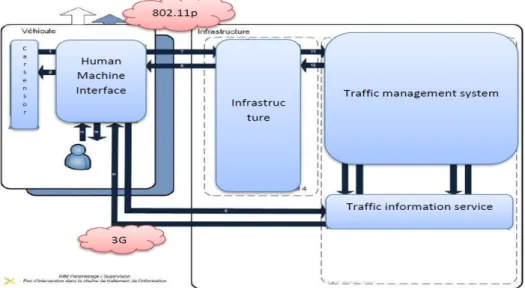
Our thesis was carried out within the framework of Co-drive and SOAPS projects. Co-Drive is a French project that is a co-pilot for an intelligent road and vehicular com-munication system. It aims at validating the pre-industrial cooperative control system between user and vehicle infrastructure. The project architecture is based on an exchange between vehicle and infrastructure through the ETSI protocol stack, or between the vehicle and the traffic information service through GPRS as shown in figure 1.1.
While SOAPS project addresses low layers protocols issues for Broadband Services pro-vision by Private Mobile Radio (PMR) systems using LTE technologies with a particular focus on the improvement of frequency resources scheduling.
1.3
Thesis Contributions
Our thesis addresses the quality of service provisioning and performance evaluation in vehicular networks in the context of IEEE 802.11p and LTE networks. More specifically, we achieved the following contributions:
• Contribution 1-Source traffic Modeling: Since network performance is highly affected by traffic variability, we started our research study by elaborating traffic modeling of vehicular applications. The selected applications fall into safety, traffic management and comfort categories.
• Contribution 2-Class of service mapping study: The panoply of vehicular applica-tions present diverse QoS requirements that should be considered when designing vehicular networks. In fact, an efficient quality of service mechanism, applied in a network, should achieve service differentiation according to traffic specifications. We strongly believe that application mapping to existing network classes of service is a crucial task in broadband and narrowband communication network. It is noteworthy that IEEE 802.11p implements service differentiation using the EDCA mechanism that adopts four access categories, whereas LTE network adopts the radio bearer concept identified by QoS Class Identifier (QCI). In this context, we achieved an original mapping study of the selected vehicular applications to access categories and LTE classes of service.
• Contribution 3-Performance analysis of the protocol stack architecture: We con-ducted a performance evaluation of the ETSI/ IEEE Wireless Access Vehicular En-vironment (WAVE) lower layers. This study is of paramount importance; in fact it enabled us to draw conclusions regarding vehicular network performance and thus to propose efficient resource allocation mechanisms that aim at enhancing quality of service.
• Contribution 4-Resource allocation mechanism: Since the vehicles are in communi-cation with multiple heterogeneous radio systems, a global management of radio re-sources is required; it enables better use of available capacity in the various networks. The developed resource allocation mechanism aims at providing a deterministic or static guarantee to user requests.
• Contribution 5-Cross-layer optimization: In the continuity of the resource allocation mechanism proposal, we pursued our studies and integrated the cross layer in LTE. In this context, we proposed to adapt the bearer priority to the achieved traffic throughput and integrated a RRC-MAC cross-layer scheme. In fact, we believe that cross layer interaction exploits dependencies of protocol layers, thereby fulfilling quality of service demands of various applications. A particular concern is devoted to the RRC-MAC cross layer scheme: the quality of service is highly affected by the MAC layer resource allocation configured by the RRC layer. Performance drastically degrades when the RRC layer does not adopt an efficient scheduling algorithm; whereas good performance is achieved when RRC cooperates with the MAC layer. Therefore, a close coordination between the MAC layer and the RRC layer is required leading to the cross-layer implementation.
In order to validate the proposed mechanisms, we elaborated analytical models using Markov Chain coupled with discrete event simulation batches.
1.4
Organization of the Thesis
The thesis is organized as follows.
Before proceeding with the contributions achieved in LTE and 802.11p networks, we devote Chapters 2 and 3 for presenting the architecture of the tackled networks. More specifically, Chapter 2 addresses vehicular networking architectures. We start by reviewing the dif-ferent characteristics of vehicular communications then describe the main characteristics of vehicular adhoc networks. Afterwards, we exhibit the general architecture of vehicular networks focusing on the functional entities. In a second step, we overview the various standards that tackle vehicular communications. Since, we contributed in this thesis to quality of service provisioning in vehicular networks, we focus in this chapter on the na-tive QoS mechanisms devised for 802.11p wireless networks and detail the MAC layer in wireless access for vehicular environment.
Chapter 3 is dedicated to LTE functional and protocol stack architecture description in user and control plans. Moreover, we focus on quality of service mechanisms suggested at LTE radio level. We orient our efforts as well towards identifying LTE classes of service.
The chapter 4 is devoted to the study of the applications envisionned in vehicular net-works. We mainly tackle the services required by Co-Drive, namely: Warning to a foggy zone, Inter-distance measurement and Road warning event. We bring the focus as well to four services taken into account in SOAPS: Voice, Video, HTTP and FTP. Then, we
detail the achieved task 1; we perform an accurate traffic modeling. This will help us to evaluate the performance modeling of the networks in the subsequent chapters.
The third contribution is detailed in chapter 5 and 6. In fact, chapter 5 provides a mathematical modeling of the WAVE physical and Mac layers, while taking into account source traffic models. The study is achieved in a V2I scenario at a large scale and burst scale.
Chapter 6 tackles the virtual collision management proposed by IEEE in vehicular envi-ronment. In fact, EDCA virtual collision management is a penalizing process that induces unfairness, priority inversion and quality of service degradation. This chapter describes the performance study of the virtual collision.
Chapter 7 sheds the light on LTE performance. It details the fourth contribution which consists of a mathematical model and performance evaluation of the Medium Access Con-trol (MAC) layer scheduling algorithm. The study while considers source traffic charac-teristics along with an original applications mapping.
Chapter 8 sheds the light on the fifth contribution. It describes an enhanced scheduling algorithm integrated in a RRC-MAC cross-layer framework. The performance evaluation of proves the performance of the scheduling algorithm. Finally, Chapter 9 addresses our perspectives and the envisionned works that deserve further investigation.
Vanet Architecture and Overview
2.1
Introduction
In this chapter, we address vehicular networking architectures. We start by reviewing the different characteristics of vehicular communications then describe the main charac-teristics of vehicular adhoc networks. Afterwards, we exhibit the general architecture of vehicular networks focusing on the functional entities. In a second step, we overview the various standards that tackle vehicular communications. Since, we contributed in this thesis to quality of service provisioning in vehicular networks, we focus in this chapter on the native QoS mechanisms devised for 802.11p wireless networks and detail the MAC layer in wireless access for vehicular environment.
We start the chapter by an overview of different types of vehicular communications in section 2.2, then in section 2.3 we discuss their characteristics. In section 2.4 we describe the main functional entities, after that we present three main standard architecture and protocols in section 2.5 with a particular focus on the QoS mechanisms and physical layer characteristics.
2.2
Vehicular Communications V2I/V2V
In intelligent transport systems, each vehicle takes the role of the sender, receiver and router to disseminate information on the network of vehicles or transportation agency. Vehicular networks are responsible for communication between vehicles moving in a cer-tain environment. A vehicle can therefore communicate directly with other vehicles, this communication is then called Vehicle to vehicle (V2V) or with the infrastructure, and this type of exchange is called thus Vehicle to Infrastructure (V2I) communication [33].
In order to establish communication between vehicles and infrastructure RoadSide Units (RSU), vehicles must be equipped with a radio interface or a vehicle unit OnBoard Unit (OBU), which allows network without short thread scope be trained. Vehicles must also be fitted with equipment that collects detailed location information such as Global Posi-tioning System (GPS) or Differential GPS (DGPS). Infrastructure can be placed at regular intervals, or integrated into existing road infrastructure, for example, road signs, bridges or toll barriers. Indeed, the number and distribution of RSU units depends on the com-munication protocol used. For example, some protocols require that road units must be distributed uniformly in the road network, while other positioning these units only at intersections.
2.2.1 Vehicle to Vehicle Communications
The configuration of the inter-vehicle communication uses multi-hop broadcast to transmit traffic across multiple hops to a group of receivers. In intelligent transport systems, there are two types of inter-vehicle message: naive dissemination and intelligent distribution. Indeed, in the naive broadcast, vehicles periodically send broadcast messages at regular intervals. Upon receiving the message, the vehicle ignores the message if it is coming from a vehicle behind him. If the message is from a vehicle in front, the vehicle receiver sends its own broadcast message to vehicles behind. This ensures that all vehicles moving in the direction of diffusion receive all broadcast messages. The limits of naive diffusion method are that a large number of messages are generated, thus increasing the risk of collisions of these messages resulting in increased end-to-end transmission delay.
Regarding intelligent broadcasting with implicit acknowledgment, it addresses the prob-lems inherent in the naive broadcast by limiting the number of broadcast messages for a given emergency event. If the vehicle detects an event and receives the same message from vehicles that are behind him, he assumes that at least one of these vehicles received the message, it is going to stop playing. The assumption is that the vehicle behind will be responsible for routing the message to the rest of the vehicles. If a vehicle receives a message from multiple sources, it will considere the first message received only.
2.2.2 Vehicle to Infrastructure Communications
The vehicle to infrastructure configuration is to simply jump diffusion; indeed, the RSU sends a single broadcast message to all vehicles in its coverage area.
The vehicle to infrastructure communication provides a high bandwidth link between vehicles and RSUs; they can be placed every kilometer or less, thereby maintaining high data rates in heavy traffic. For example, during the delivery of dynamic speed limits,
the infrastructure will determine the appropriate speed limit based on internal traffic conditions. It will therefore periodically broadcast a message containing the speed limit and compare geographic areas and directional terms with the vehicle data to determine whether a speed limit warning applies to all vehicles in the neighborhood. If a vehicle violates the required speed limit, a broadcast will be delivered to the vehicle asking the driver to reduce speed.
2.2.3 Routing Based Communications
The routing-based communication is a multi-hop unicast where the message propagates in multi hop until the vehicle carrying the desired data is reached. When a request is received by a vehicle having the desired information, the application at the vehicle immediately sends a unicast message containing the information about this vehicle, which is then responsible for forwarding the request to the source.
2.3
Vehicular Networks Characteristics
Indeed, VANET networks share many characteristics with the MANET, however, there is an important difference between the two networks. In the following, we describe some characteristics [34], as well as various standardization efforts in this area.
Network topology and density: Because of the high mobility of vehicles, the vehicu-lar network topology changes frequently; a vehicle can join and leave the network in a very short time which indicates a wide variation in vehicle density. In addition, the vehicle den-sity can vary from an environment to another (for example, urban or rural environment). Thus, the vehicular networks protocols are facing the challenges of density variation.
Indeed, V2V communications can extend all the way. However, the road network limits the topology of the communication network to one dimension. In fact, obstacles prevent wireless signals to cross between roads, except near intersections
Mobility Model: Vehicle mobility is constrained by the taken paths, the management and the number of traffic lanes; therefore, the vehicle pathways are predictable in advance. Furthermore, the constraints imposed by the obstacles, traffic and the speed limit lights; greatly affect the mobility model and vehicle density.
The vehicles often travel at a very high speed; however, their movements are constrained by the road topology. Moreover, the decision of the driver is related to vehicle performance
limitations and to traffic laws. Therefore, the mobility of the vehicle is predictable on the roads.
Large Scale: Vehicular networks are developing at a very large scale; they are based on a diffusion process. Therefore, protocols face collisions and possible interference between communications vehicles.
Security: Data security and privacy remains one of the major problems in vehicular networks. Indeed, the attacks of the network can generate a road accident, which makes its wireless network extremely vulnerable. It is therefore essential to design protocols that secure network access.
2.4
Description of The Functional Entities
The 802.11p network is recommended for wireless access in vehicular network. The archi-tecture of the IEEE 802.11 is composed of several components that interact to provide a wireless network. In this section, we present the functional entities of 802.11p architecture network as shown in Figure 2.1 [1] .
Figure 2.1: Functional entities [1]
2.4.1 Basic Service Set (BSS)
A BSS is a set of stations (STA) under the control of one coordination function. The geo-graphical area covered by the BSS is known as Basic Service Area (BSA). To be a member of the BSS, a station must apply a synchronization procedure. A single Independent BSS (IBSS) form an ad-hoc network without infrastructure.
2.4.2 WAVE Basic Service Set (WBSS)
Two devices (or more) involved in WAVE communication form a WAVE Basic Service Set (WBSS). In order to initiate communication, an RSU or OBU transmits WAVE announce-ment frames, the equipannounce-ment that initiated the WBSS is called provider, who receives these frames and establishes communication with the supplier called user. The OBUs and RSUs can be provider or user of a service. A unit can switch from vendor status to the user status of a service but cannot be in both states simultaneously. So there are two types of WBSS:
• A persistent WBSS is announced periodically and may be used to carry a current service indefinitely (ie, Internet access).
• A non-persistent WBSS is announced at the initiation WBSS and will be for a limited time. It is interesting to carry demand services.
2.4.3 Access Point (AP)
The infrastructure networks are established through the Access Point (AP), it is mapped to the RSU unit of the connecting road. The AP has the base station functionality in cellular networks. It represents the entity that allows access to the distribution system through the wireless medium.
2.4.4 Distribution System (DS)
The distribution System (DS) is an architectural component used to interconnect multiple BSSs. This allows the different stations to communicate with other BSS via multiple APs.
2.4.5 Extended Service Set (ESS)
The SSE is the union of several BSS connected by a DS. The stations can communicate within an ESS and move from one BSS to another.
2.5
Available Standards and Protocols
2.5.1 European Telecommunications Standards Institute (ETSI)
Archi-tecture
ISO standardization efforts are based on the concept of Communications Access for Land Mobiles (CALM) and ETSI have opened the way for cooperative vehicle systems. ETSI
proposal presents a more detailed view of a stack of communication that should be instan-tiated on personal items, vehicles, roads and its stations ITS, where common OSI layers are surrounded by two plans for the management and security .
This architecture is managed and maintained by the Standard (ETSI) [2] to develop stan-dards and specifications of its services. ETSI architecture (figure 2.2) [2] has four vertical layers (application, facilities, network and transport, and link layer) and two vertical planes: management and safety plans.
Figure 2.2: Architecture ETSI [2]
2.5.2 Communication Access for Land Mobiles (CALM ) Architecture
This architecture is proposed by the ISO standard [3]. The main objective is to develop a CALM standard network protocol that is able to connect vehicles and roadside systems continuously and seamlessly. Thus, CALM provides a multitude of cellular mobile com-munication media and wireless networks, Dedicated Short-Range Comcom-munication (DSRC) or even InfraRed (IR). This reuse (figure 2.3)[3] of the existing communication media can be explained by the fact that the CALM wishes to use the predefined standards. For the routing issue, CALM uses IPv6 as a routing protocol with transfer media.
Figure 2.3: Architecture CALM [3]
2.5.3 Wireless Access for Vehicular Environment (WAVE) Architecture
Several standards IEEE P1609.1, P1609.2, and P.1609.3 P.1609.4 (figure 2.4 ) [1] are de-veloped for vehicle networks forming the WAVE architecture [1], it is based on DSRC standard. In fact, it carries communications in a short range dedicated band in order to issue on unused frequencies of other standards to reduce interference. WAVE recommends the IEEE 802.11p standard which governs the protocols at the MAC layer and physical. IEEE 802.11p standard is based on the IEEE 802.11a physical layer and IEEE 802.11 e for the quality of service. In the following, we will discuss the various components of the WAVE architecture.
The IEEE 1609.1 [35] processes the format of the messages exchanged between vehicles and their neighbors or between vehicles and infrastructure, as well as the necessary data to be stored in vehicles. It is related mainly to VANET applications and specifies the needs of each category in terms of time and data. The IEEE 1609.2 [36] standard describes the security mechanisms required in an automotive environment.
The IEEE 1609.3 [37] standard describes the Wave Short Message Protocol (WSMP) that replaces the TCP / IP stack and manages urgent applications. And high-priority data will be sent in a small time window. The WSMP message can be transmitted on the Control Channel (CCH) and the Service Channel (SCH). The standard therefore provides
for the presence of a single channel CCH, reserved for control and safety messages, and up to 6 SCH channels used to transmit non-safety data messages. Indeed, WAVE supports IP and non-IP applications. Short Messages WAVE (WSMS) consume minimal chan-nel capacity, they can be sent over the chanchan-nels CCH and SCH. Unlike the IP traffic that can be sent on the SCH only, the system management frames are sent on the CCH channel.
Physical and MAC layers are defined by IEEE 1609.4 standards [38]. The standard defines multichannel coordination and describes the process for setting priorities among different traffic. According to the multi-channel coordination mechanism, all stations must monitor the CCH for common time intervals and move to a SCH channel if they want to transmit insecure messages applications.
Figure 2.4: WAVE Architecture
WAVE accommodates two protocol stacks: the standard stack (TCP / UDP, IPv6) and the WSMP protocol recommended for wireless access in vehicular environments. More precisely, the data plan incorporates the following protocols:
• The protocol Logical Link Control (LLC).
• The protocol Internet Protocol version 6 (IPv6).
• The protocol User Datagram Protocol (UDP) and Transmission Control Protocol (TCP).
• The protocol WSMP: it allows applications to directly control the characteristics of the physical layer, ie: the channel number and transmission power. The sending application also provides the MAC address of the destination terminal.
In the following, we present the functional architecture of WAVE standard for vehicular networks and the protocol stack adopted by ETSI. In fact, we used both architectures in Codrive project. Specifically, we have adopted a top-down approach starting with the
upper layers of the ETSI standard.
The Facilities layer is supported by the standard protocol stack (TCP / UDP, IPv6) and the IEEE 802.11p. This new architecture is intended to transmit specific ITS mes-sages applications on WAVE protocol stack standard. These mesmes-sages are standardized in two categories Cooperative Awareness Messages (CAM) and Decentralized Environmen-tal Notification Messages (DENM). Therefore, road applications are standardized as CAM DENM messages. they are received and interpreted by the Facilities layer before sending them to network and transport layers in which we distinguish between ITS or TCP / UDP transport stack.
2.5.3.1 The Facilities Layer
The Facilities layer is a new paradigm introduced by ETSI. Its main features are merging and management of various data. This layer is also responsible for updating the database dynamically, so that it can be used by applications. The Facilities layer is defined in the standard by a set of modules responsible for interacting with ITS applications and network and transport layers (Figure 2.5).
It provides for ITS applications support to share functions and generic data according to their business needs. We therefore examined the functional architecture and components [39], it summarizes the main features of the facilities layer. Indeed, it focuses on addressing data at this level and the inters-layer communications interfaces through Service Access Point (SAP).
The Facilities layer consists of two vertical planes: Common and Domain Facilities. • Common facilities: The plan defines the basic generic services for all ITS
applica-tions; Human Machine Interface (HMI) common, the addressing mode; V2X mes-sages; management of CAM messages...
• Domain facilities: It specifies personalized services and functions for a class of ITS applications among these functions: managing expectations queues based on the priority of V2X messages and verification of the relevance of the messages.
Both plans are decomposed into three layers: Application Support, Information Support and Communication Support.
• Application support facilities: this layer carries the ITS services; such as CAM and DENM message manager.
• Information support facilities: it provides data stored and managed in a common database called Local Dynamic Map (LDM) containing the images and information of the road.
• Communication Support facilities: this layer provides services for the communication manager and session.
The Facilities layer has a GUI interface that allows interaction with users, it transmits messages that contain the route information but also location data: longitude, latitude and altitude. The information support contains a temporary database called LDM; it stores the route information dynamically.
This layer allows also the management of messages exchange between applications: con-struction of CAM or DENM messages, session management messages (request message, response message). Each message is identified by an address and sent to the network and transport layers through Service interfaces Access Point (SAP).
The importance of addressing messages at the application level is to identify ITS applica-tions (using the ITS-AID), and to identify the type of messages sent by applicaapplica-tions (using FTM -ID) [39], and allows lower layers to access each application data.
2.5.3.2 Transport/ Network Layer
This layer is responsible for routing packets through the network. It generally implements two protocols: TCP and UDP.
2.5.3.3 MAC Layer
The MAC layer [1] should provide a reliable access to the channel, equitable and effective. We must therefore take into account the different types of applications. For example, safety messages applications must be sent quickly and with very low loss rate. This re-quires effective sharing of the channel, which is even more difficult because of the high mobility of vehicles and fast topology changes.
The quality of service provisioning for real-time applications with strict time constraints require reliable transmission. This is due to resources fluctuation, high vehicle speeds and physical propagation conditions on the radio channel. The 802.11p standard provides two QoS mechanisms [1]:
• The first mechanism is distributed called Enhanced Distributed Channel Access (EDCA). It transmits traffic according to user priorities (User Priorities) (UPs). • The second mechanism is centralized and is designated Hybrid Coordination
Func-tion Controlled Channel Access (HCCA). It allows the reservaFunc-tion of permissions transmission (Transmission Opportunities (TXOPs)). The following paragraphs de-tail the two mechanisms built at the MAC layer figure 2.6 [1].
Figure 2.6: MAC Layer [1]
2.5.3.4 QoS Mechanisms of The MAC Layer
The quality of service is the ability to transmit in good conditions a given type of traffic, in terms of availability, throughput, transmission delay, jitter, packet loss rate, it aims to optimize network resources and ensure good performance for critical applications. The guarantee of a good QoS in vehicular conditions that introduce resource fluctuations, high vehicle speeds and difficult physical propagation conditions at the radio channel is not
easy. The QoS support begins in a network of the same priority flow aggregation in differ-ent classes, the QoS must be maintained throughout the flow crossing through the various layers. To maintain this QoS, the IP layer flows will be mapped on the relevant priorities offered by DiffServ, and then mapped on the QoS offered by the MAC layer.
In fact, the MAC layer provides two types of function: The function Point Coordination Function (PCF) and the Hybrid Coordination Function (HCF) through the Distributed Coordination Function (DCF). CPF mechanisms and HCF DCF will be described in the following.
The medium mode alternates between contention during the Contention Period (CP) and no contention mode during Contention Free Period (CFP). In CP, the stations are competing for access to the transmission medium. During the CFP, the access medium is controlled by the AP; this eliminates any temptation to contention and collision.
Distributed Coordination Function (DCF) DCF in figure 2.7 is the fundamental access method implemented in all stations belonging to the IBSS or to network infrastruc-ture. DCF is based on Carrier Sense Multiple Access with Collision Avoidance mechanism (CSMA / CA). Each station has awaiting MAC Service Data Unit (MSDU), should the access contention to access the channel. This contention will be repeated for all waiting frames in the queue at the MAC layer.
Figure 2.7: Mechanism DCF [1]
The medium access priority is controlled by the use of time slots Inter-Frame Space (IFS) which separate the frames transmissions.
Three IFS intervals are specified in the standard: Short-IFS (SIFS), Point Coordination Function-IFS (PIFS) and Distributed Coordination Function (DIFS). The interval SIFS is
lower than PIFS, and lower than DIFS. A station that wishes to issue, should ensure that the channel is free during the DIFS interval before attempting transmission (figure 2.7) [1].
If the channel is free, then the station transmits a data frame. When the frame is trans-mitted, the frame duration field is used to notify the stations of the time during which the medium is busy. All stations, having received the data frame, update the Network Allocation Vector (NAV) which indicates the time remaining for the current transmission is completed.
In the case where the station detects that the channel is busy, it waits until the channel is free during DIFS. Then, it calculates the backoff length. This period of backoff is decre-mented as the channel is free for the Contention Window CW period.
• If the backoff reaches zero, the station transmits the frame.
• If two stations have a backoff period equal to zero simultaneously, a collision then occurs. Each station should generate a new backoff time.
• If the channel becomes busy and backoff time has not reached zero, the station freezes the backoff time.
An improvement of this mechanism is developed through the exchange of RTS / CTS frames (Figure 2.8)[1] that aim to minimize collisions. A station that wishes to transmit sends a RTS frame to the AP. It sends a CTS frame broadcast to indicate the reservation of the channel by the concerned station.
Figure 2.8: Mechanism DCF with RTS/CTS [1]
Point Coordination Function (PCF) The PCF provides a centralized mechanism used only in networks with infrastructure. A Coordinator Point working with the access
point performs the polling of active stations and determines the station with the right to transmit.
Hybrid Coordination Function (HCF) The HCF mechanism improves the PCF and DCF functions by integrating QoS mechanisms and specific types of frames. HCF is based on the access method of the EDCA contention channel and on the controlled access method of the HCCA channel.
HCF Controlled Channel Access (HCCA) HCCA mechanism with a hybrid coor-dinator (HC) is the central body responsible for the quality service provisioning.
HC uses the highest priority level to access the medium in order to initiate frame exchanges and to allocate TXOPs to itself and other stations.
A station sends a request to HC asking for TXOPs (in uplink and downlink transmissions) based on the requirements of its traffic. HC admission control policy allows deciding the acceptance or rejection of the request from the station.
The HC has a global view of the network and known traffic conditions belonging to various categories of service in queues stations. This is the basis for the allocation of TXOPs and transmissions without restraint by the various stations of the traffic carried.
EDCA mechanism The EDCA mechanism provides a distributed method to the wire-less medium access with QoS differentiation. Specifically, this mechanism is based on eight different priorities that are matching, in ascending order of the four priorities as shown in Figure 2.9 [1].
Eight User Priorities (UP) levels, it is an integer between 0 and 7. Each access class is mapped to one UP accordance to figure 2.9. The quality of service differentiation is obtained by varying the following parameters:
• Arbitration Inter-Frame Space (AIFS): Minimum time interval between the instant when the medium is free, and the start of transmission of the frame.
• Contention window (CW): a gap in which a random number is selected in order to implement the back-off mechanism.
• Transmit Opportunity Limit (TXOP): The maximum amount of time (in millisec-onds) during which a station can transmit after receiving a TXOP. In case TXOP is zero, the station can transmit a single MSDU.
The packets are sent to the radio medium according to the DCF, but using a setting own of each category. Indeed, internal collisions can occur, it is possible that two packets in two different queues in a same station have their random wait time ends at the same time. Data packets must indicate whether a quality of service is requested, for this, the quality of service field in the frame control field is activated, it provides information on the quality of service associated with the respective frame such as the priority degree.
2.5.3.5 Physical Layer and Dedicated Short Range Communication (DSRC) The standard Dedicated Short Range Communication (DSRC) [4] is defined by American Society for Testing and Materials (ASTM) to ensure vehicular communications. WAVE is the standard defined by the IEEE group, this standard is dedicated to V2V and V2I communications and supports IEEE 802.11p, it uses the concept of multi-channels. All channels functionally dividing into one Control Channel (CCH) and 6 Service Channels (SCH).
The physical layer of WAVE [9] is derived from the IEEE 802.11a. It is able to offer a rate between 3 and 27 Mbps on 10MHZ channel (for distances up to 1000 meters) with Orthogonal Frequency Division Multiplexing (OFDM) modulation.
The physical layer is based on seven communication channels of 10 MHz each a length lying in the area 5.850 and 5.920 GHz. WAVE devices must be able to accommodate an architecture that supports a CCH channel and multiple SCH channels to ensure commu-nications for security applications and other Intelligent Transport service.
The control channel is reserved for the transmission of network management messages and high priority messages such as: critical information related to road safety. The six other
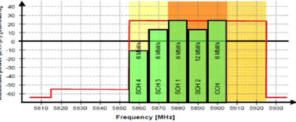
channels in figure 2.10 [4] are on the other dedicated to the transmission of data from different services. Finally, note that the protocol should allow unicast and multicast, the different channels can be used simultaneously, however, each station continually alternates between the control channel and service channels. In order to meet safety requirements (collision avoidance) a period containing a CCH and SCH should not take more than 100ms.
The figure shows the channels envisaged for the WAVE standard. A control channel and several service channels are recommended. It should be noted that the entire SCH channel will not be used.
Figure 2.10: WAVE standard channels [4] According to European standard
• ITS-G5A: Frequency band of 5.875 GHz to 5.905 GHz, dedicated to security ITS applications,
• ITS-G5B: Frequency band from 5.855 GHz to 5.875 GHz, dedicated to comfort ITS applications (non-safety)
• ITS-G5C: Frequency range from 5.470 GHz to 5.725 GHz, dedicated to other types of applications.
The physical layer protocols must address the multiple changes of fading and Doppler fre-quency caused by nodes mobility. Experimental communications vehicle-to-vehicle used radio and infrared waves. [47] Very high frequency, microwave, and millimeter wave radio waves are examples used for V2V communications. The physical layer protocols must ad-dress the multiple changes of fading and frequency caused by nodes mobility. In contrast; both infrared and millimeter waves are only suitable for the targeted communications, while the microwaves provide broadcast communications. In particular, the high frequency communications support low-speed links and, therefore, the tendency is to use microwave.
(DSRC) operates in the 5.9GHz band for the use of public safety and private applications [26]. In the US, the Federal Communications Commission (FCC) has allocated 75 MHz in
the band for DSRC 5.850-5.925GHz while the ETSI standard has allocated 30 MHz in the band 5.875-5.905GHz (Figure 2.11). DSRC supports a vehicle speed up to 200 km/h, a nominal transmission range of 300m (up to 1000 m), and the default data rate of 6 Mbps (up to 27Mbps). This frequency band is divided into six service channels (SCH) and a control channel (CCH) with the same bandwidth of 10 MHz each. In the DSRC standard, the whole spectrum is divided into time intervals of 50 ms and messages have two different priorities: low for data broadcast messages transmitted on SCH channels or higher for safety messages or transmitted on the control channel CCH.
If the CCH channel is active, all nodes must stop their communication during the period of CCH to receive and transmit safety messages on the CCH channel. Indeed DSRC standard is proposed to facilitate communication between vehicles and roadside units. In the IEEE 802.11 standard, DSRC is known as the IEEE 802.11p WAVE. WAVE protocols propose changes to the physical layer and MAC of the existing IEEE 802.11 standard to support its applications. This would include the exchange of data between high-speed vehicles and between vehicles and the road infrastructure in the 5.9GHz band. The ultimate goal is to have the WAVE standard as an international standard in the world.
Figure 2.11: European standard channels allocation
2.6
Conclusion
The main goal behind this chapter was to present VANETs networks as a new network paradigm in the research field. Hence, VANETs emerge as a specialized form of MANETs with specific requirements related to the specific characteristics of such networks. A large number of research and standardization efforts have been carried out during last decades and was briefly presented in this chapter. We have also described the most important architectures dedicated to vehicular networks with a special focus on WAVE architecture as it was used as a reference networking stack in the next chapter. Moreover, we classified vehicular applications based on their impact on the road traffic and the requirements
of each category in terms of delays and services. We presented for each category some key schemes to well understand the added value of each category. Next chapter will be dedicated to LTE architecture.
LTE Architecture and Overview
3.1
Introduction
A wide variety of applications for road safety and traffic efficiency are intended to an-swer the urgent call for smarter, greener, and safer mobility. Although IEEE 802.11p is considered in the standard for on-the-road communications, stakeholders have recently started to investigate the usability of Long Term Evolution (LTE) to support vehicular applications. Therefore, we oriented our efforts towards studying LTE technology. The current chapter is devoted for presenting LTE functional and protocol stack architecture in user and control plants. Moreover, we focus on quality of service mechanisms suggested at LTE radio level.
This chapter is organised as follow: the following section 3.2 describes the main entities of LTE architecture, in section 3.3 we show the QoS concept in LTE followed by section 3.4 where we discuss RLC, MAC, and physical layers in both control plane and user plane.
3.2
LTE Architecture
The result of the 3GPP standardization [5] effort is the Evolved Packet System (EPS) that consists of the core network part, the Evolved Packet Core (EPC) and the radio network evolution part, the Evolved UTRAN (E-UTRAN), also known as LTE. The EPC can also be connected to other 3GPP and non-3GPP radio-access networks. As illustrated in Figure 3.1 [5], the EPC consists of some control-plane nodes, called Mobility Manage-ment Entity (MME), control Home Subscriber Server (HSS) and two user-plane nodes, called Serving Gateway (S-GW) and Packet-data Network Gateway (P-GW). The LTE radioaccess network consists of the base stations, denoted as enhanced NodeB (eNb), that are connected to each other through the X2 interface and to the EPC through the S1 interface. The mobile terminal is denoted as User Equipment (UE).
Figure 3.1: Overview of the EPC/LTE architecture [5]
Serving Gateway (S-GW): The S-GWmaintains Service Data Flow (SDF) context for the default/dedicated bearers establishment. It is also in charge of the mobility anchor for inter-eNb and inter-3GPP access mobility Packet.
Packet-data Network Gateway (P-GW): Is the entrance and the exit point for data traffic in the EPC. The P-GW performs policy enforcement and packet filtering for each data flow of each subscriber. It maintains the context for each connection of the mobile device, the traffic flow templates for the active services, the QoS profile and the charging characteristics.
Mobility Management Entity (MME): MME is the central management entity for the LTE accesses. It is responsible for the connection of the UE by selecting the gateway through which messages are to be exchanged and a level of resources for theUE in cases of attachment and handover. It also provides authentication and authorization and location tracking using the HSS and intra-3GPP mobility (e.g. between 2G/3G and LTE).
Home Subscriber Server (HSS): The basic HSS function is the control of user sub-scription data.
Enhanced Node B (eNb): The Enhanced NodB (eNb) hosts the following functions; Radio Resource Management (RRM) (Radio Bearer Control, Radio Admission Control, Connection Mobility Control, Dynamic allocation of resources to UEs in both uplink and downlink), IP header compression and encryption of user data stream, selection of an MME at UE attachment, routing of user plane data towards SAE Gateway, measurement and measurement reporting configuration for mobility and scheduling. The eNb is in charge of an important QoS task which is the efficient performance of radio resource allocation.
3.3
Quality of Service (QoS)
The one important benefit of LTE is realised by networks which dynamically accommodate a mix of real and non-real time services. An end-to-end, class-based Qos architecture has been defined for LTE in order to support such a mix of services.
Indeed, the Qos aspect in LTE is very important, for that concern it is composed of two important components, the backhaul and the MAC air interface.
The backhaul part is devoted to an effective processing of packet flows using good policies, it manage the QoS between the eNb and the gateways, this later is in charge of setting the adequate parameters for an efficient packet flows management. The MAC air interface like its name suggest will handle the distribution of the packets in the wireless part of the network, it is therefore located in the eNB.
3.3.1 The Bearer
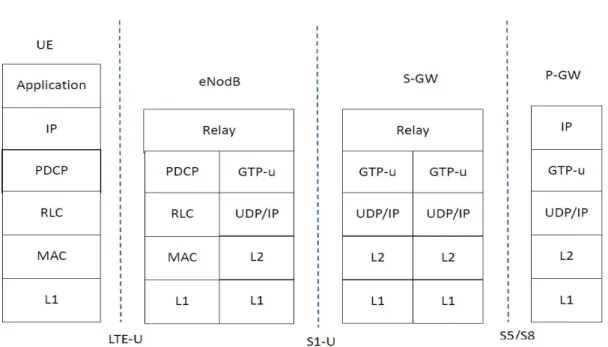
The QoS mechanism is based on the class-based data flows and bearers concept, as shown in Figure 3.2. Data flows are mapped to bearers, with three individual bearers according to three interfaces (Radio, S1 and S5/S8) combined to provide the end-to end QoS support via the EPS Bearer.
Figure 3.2: Types of Bearers [5]
The class-based QoS approach enables bearers to be mapped to a limited number of dis-crete classes. Network nodes can be preconfigured for these classes.
The LTE QoS is carried out using a paramount element named Bearer. This element has the very important task of identifying the appropriate QoS processing of the flows between the user equipment and the gateway. Each bearer gives the same packet forward-ing treatment common to all flows mapped to that bearer (link layer configuration, queue management policy, scheduling policy ...).
![Figure 2.1: Functional entities [1]](https://thumb-eu.123doks.com/thumbv2/123doknet/14586635.729766/35.892.170.681.655.900/figure-functional-entities.webp)
![Figure 2.2: Architecture ETSI [2]](https://thumb-eu.123doks.com/thumbv2/123doknet/14586635.729766/37.892.163.690.414.734/figure-architecture-etsi.webp)
![Figure 2.3: Architecture CALM [3]](https://thumb-eu.123doks.com/thumbv2/123doknet/14586635.729766/38.892.189.746.152.515/figure-architecture-calm.webp)
![Figure 2.5: Facilities Layer [39]](https://thumb-eu.123doks.com/thumbv2/123doknet/14586635.729766/40.892.196.743.783.1051/figure-facilities-layer.webp)
![Figure 2.8: Mechanism DCF with RTS/CTS [1]](https://thumb-eu.123doks.com/thumbv2/123doknet/14586635.729766/44.892.221.718.792.998/figure-mechanism-dcf-with-rts-cts.webp)
![Figure 3.2: Types of Bearers [5]](https://thumb-eu.123doks.com/thumbv2/123doknet/14586635.729766/52.892.188.777.643.857/figure-types-of-bearers.webp)