HAL Id: tel-01526685
https://tel.archives-ouvertes.fr/tel-01526685
Submitted on 23 May 2017HAL is a multi-disciplinary open access archive for the deposit and dissemination of sci-entific research documents, whether they are pub-lished or not. The documents may come from teaching and research institutions in France or abroad, or from public or private research centers.
L’archive ouverte pluridisciplinaire HAL, est destinée au dépôt et à la diffusion de documents scientifiques de niveau recherche, publiés ou non, émanant des établissements d’enseignement et de recherche français ou étrangers, des laboratoires publics ou privés.
radio frequency wave-plasma-wall interactions in the
magnetized plasma device under ion cyclotron range of
frequencies
Lingfeng Lu
To cite this version:
Lingfeng Lu. Modelling of plasma-antenna coupling and non-linear radio frequency wave-plasma-wall interactions in the magnetized plasma device under ion cyclotron range of frequencies. Accelera-tor Physics [physics.acc-ph]. Université de Lorraine, 2016. English. �NNT : 2016LORR0173�. �tel-01526685�
AVERTISSEMENT
Ce document est le fruit d'un long travail approuvé par le jury de
soutenance et mis à disposition de l'ensemble de la
communauté universitaire élargie.
Il est soumis à la propriété intellectuelle de l'auteur. Ceci
implique une obligation de citation et de référencement lors de
l’utilisation de ce document.
D'autre part, toute contrefaçon, plagiat, reproduction illicite
encourt une poursuite pénale.
Contact : [email protected]
LIENS
Code de la Propriété Intellectuelle. articles L 122. 4
Code de la Propriété Intellectuelle. articles L 335.2- L 335.10
http://www.cfcopies.com/V2/leg/leg_droi.php
Modelling of plasma-antenna coupling and non-linear radio
frequency wave-plasma-wall interactions in the magnetized
plasma device under ion cyclotron range of frequencies
by:
LingFeng Lu
Board of examiners for public PhD defence on December 2
nd, 2016
Prof. Michel Vergnat
Chair-ULorraine
Prof. Rik Van de Walle
Co-chair-UGent
Prof. Nong Xiang
Referee-ASIPP
Prof. Daniel De Zutter
Referee- UGent
Dr. Annika Ekedahl
Referee-HDR Aix-Marseille U
Dr. Dirk Van Eester
Examiner-ERM/KMS
Dr. Philippe Jacquet
Examiner-CCFE
Dr. Laurent Colas
Supervisor-HDR ULorraine
Prof. Jean-Marie Noterdaeme
Supervisor-UGent/MPI
Prof. Kristel Crombé
Thesis promotor-UGent/ERM
Prof. Stéphane Heuraux
Thesis promotor-ULorraine
Institut de Recherche sur la Fusion par confinement Magnétique
CEA Cadarache 13108 Saint-Paul-lez-Durance, France
Acknowledgement
Thanks to the support from Erasmus Fusion-DC program, I had the opportunity to conduct a thesis in France and Belgium under the guidance of an international committee. I am greatly thankful to my four supervisors, Dr. Laurent Colas (IRFM, CEA), Prof. Kristel Crombé (LPP, ERM/KMS), Prof. Stéphane Heuraux (IJL, Université de Lorraine) and Prof. Jean-Marie Noterdaeme (IPP Garching). Your profound knowledge and conscientious attitude towards scientific work always encourage me and set an example for my future research career.
I spent 2 over the total 3 years in IRFM, which locates in the picturesque countryside of Provence. I would like to thanks all the members of the GCHF group which I affiliated for their company. Special thanks to Walid Helou and Julien Hillairet for the useful technical discussions on RF engineering. I learned a lot from them. Also thanks Annika Ekedahl to be one of my reporters of the thesis defence. Thanks Robert Volpe for the interesting and funny discussions on Asterix and let me know many Italian/French cultures. Besides, I would like to thanks Nathalie Borio, Karine Ruiz for many practical helps. The SSWICH-FW I developed in this thesis is a successor of the previous work did by Jonathan Jacquot. During this thesis, I got many useful suggestions concerning the code development. Also he provided me the field map from his 3D RAPLICASOL code. Many thanks for these helps.
The 6 month’s stay in LPP is my busiest time during this 3 years. The lab is compact but really have many talented people. We are lucky to have our Wikipedia André Messiaen with us, who have almost simulated everything. Thanks Fabrice Louche for many beneficial discussions on RF simulations and also Riccardo Ragona who shares the COMSOL workstation with me. I need acknowledge Benedicte schifflers for many practical helps. Finally, many thanks to my co-director in this lab: Dr. Dirk Van Eester, who always have many ideas and show great passion and optimism during the work as well as in the afterwork chat. One of the most fascinating things during my thesis is that I had the honor to work with so many elites that I knew before from reading scientific articles. Dirk is definitely one of them. I also owe my gratitude to Fusion DC administrative staffs, Kathleen Van Oost, Frank Janssens and UGent policy officer Muriel Vervaeke from the Dean’s office of faculty of engineering an architecture who helped me solve many practical things concerning cotutelle agreement and the preparations of two doctoral defences.
The 3 month’s stay in IJL is short compared to the duration I spent in other labs. I am grateful to Eric Faudot who guided my simulation work on Aline. Our daily discussion let me learn a lot of things beyond Tokamaks. Also thanks Stéphane Devaux who kindly provided me the experimental data.
I would like to thank Prof. Rik Van de Walle (UGent), Prof. Daniel De Zutter (UGent), Dr. Philippe Jacquet (CCFE), Prof. NongXiang (ASIPP) and Prof. Michel Vergnat (ULorraine) who agreed to become my thesis juries. I am also grateful to Tycho Van Noorden from COMSOL support team who gave me a lot of useful tips on numerical implementation.
Finally, I would address my appreciation to the friends who accompanied me in the past 3 years. Thanks Laurent Valade taught me many useful French. I know from many people that as long as I can understand this Parisien, I can understand everyone. The trips we had together in UK and US won’t be forgotten all my life. Thanks Hugo Arnichand who is always so hospitable and open mind. The trips to visit Montpellier, Arles and the mountains near your holiday house are my best memories about France. Also thanks Nicolas and Alexandre Fil who watched football and went hiking with me several times. Thanks Charles Ehrlacher
telling me many interesting stories during his military service and the history of France. I am also pleased to recognize Jane Ho in Ghent. The food cooked by your father is the best food I ever ate in Belgium. I hope next time when you come to China, I could able to speak Cantonese with you.
Acronyms
AUG: Axially Symmetric Divertor Experiment (ASDEX) Upgrade
DC: Direct current
FS: Faraday screen
ICRF: Ion cyclotron range of frequencies
ICRH: Ion cyclotron resonant heating
IshTAR: Ion cyclotron sheath test arrangement
ITER: International thermonuclear experimental reactor
JET: Joint European Tokamak
LCFS: Last closed flux surface
PEC: Perfect electric conductor
PFC: Plasma facing component
PMC: Perfect magnetic conductor
PML: Perfectly matched layer
RAPLICASOL: Radiofrequency wave coupling for ion cyclotron antenna in scrape off
layer
RF: Radio-frequency
SBC: Sheath boundary condition
SOL: Scrape-off layer
SSWICH-FW: Self-consistent sheath and waves for ion cyclotron heating-full wave
SSWICH-SW: Self-consistent sheath and waves for ion cyclotron heating-slow wave
TE: Transverse electric
TM: Transverse magnetic
TOPICA: Torino polytechnic ion cyclotron antenna
TS: Tore Supra Tokamak
Overzicht
Ion cyclotron resonante verhitting (Ion cyclotron resonant heating - ICRH) is één van de belangrijkste verhittingsmethodes in de huidige Tokamaks. De golven worden opgewekt door antennes aan de rand van de Tokamak met frequenties tussen 30 en 80 MHz. Om de plasma’s voldoende te kunnen verhitten en de systemen voldoende betrouwbaar te maken voor langdurige steady-state operatie, is het van belang de antenne-plasma koppeling te begrijpen en de nefaste, ongewilde randeffecten van de nabije velden van de radio frequente (RF) golven tot een minimum te beperken.
Een ICRH antenne kan twee types van koude plasma golven uitzenden: de snelle golf (meestal de belangrijkste component) en de trage golf (parasitair). Het eerste deel van deze thesis bestudeert de invloed van een dichtheid die continu afneemt in de antenne en daarbij een resonante laag doorkruist (i.e. de lower hybrid (LH) resonantie), op de nabije RF velden en het koppelen van het vermogen naar het plasma. Hiertoe werd een 2D golf code ontwikkeld, RAPLICASOL, gebaseerd op het COMSOL Multiphysics pakket. Bij dichtheden onder de LH resonantie is het niet-triviaal gebleken om numerieke convergentie te bereiken. Tot de grenzen van het geheugen van de gebruikte computer, blijft het patroon van de velden veranderen met de grootte van het gebruikte rooster. Een fysische interpretatie is dat de trage golf zich kan voorplanten bij deze dichtheden en zeer korte golflengtes kan aannemen, en daardoor gevoelig is voor de parameters van de simulatie, zoals de grootte van het rooster. Echter, een interessante en belangrijke observatie is dat het totale spectrum dat gekoppeld wordt naar het plasma onafhankelijk is van de grootte van de cellen en slechts beperkt wordt beïnvloed door de aanwezigheid van een dichtheidsprofiel in de antenne box, vooral bij een dipool fase spectrum van de antenne. Golven met een dipool fase verschil worden meestal gebruikt voor de plasma verhitting. Voor de studie van de snelle golven en de koppeling is het daarom niet nodig om deze lage dichtheden in de antenne box in rekening te brengen. Bij antenne operatie met een monopole fasering tonen de simulaties dat er tot 20% meer vermogen in het plasma kan terecht komen als rekening wordt gehouden met de lage dichtheden. Het verschil is te verklaren door het feit dat de evanescentielengte van de snelle golf voor lage waarden van k// verandert. Dit heeft tot gevolg dat het modelleren van schema’s met lage k// waarbij wordt aangenomen dat de antennes zich in vacuüm bevinden, moet worden herbekeken. De simulaties tonen verder aan dat veranderingen in de dichtheidsgradiënt in de evanescente zone van de snelle golf geen effect heeft op de koppeling van de golven. Het is dus nog steeds mogelijk om de vermogensoverdracht naar het plasma met goede nauwkeurigheid te modelleren ondanks onzekerheden in het dichtheidsprofiel.
Grenslaag (“sheath”) effecten aan de antennes worden verantwoordelijk geacht voor het sputteren van onzuiverheden en een overdreven verhitting van antenne oppervlakken en andere componenten die in aanraking kunnen komen met plasma, zoals ook experimenteel wordt waargenomen. Om deze sheath effecten te modelleren in een realistische geometrie op schaal van een ICRH antenne werd al voor de start van deze thesis een code ontwikkeld, de SSWICH-slow wave code (Self-consistent Sheaths and Waves for ICH). Ze koppelt op een zelf-consistente wijze de propagatie van de trage golf en de DC SOL biasing via een niet-lineaire RF en DC sheath randvoorwaarde die wordt toegepast op de interfaces tussen het plasma en de wand. Een eerste versie van SSWICH had een 2D toroïdale en radiale geometry
en rechthoekige wanden die hetzij loodrecht, hetzij parallel waren met het magnetische veld B0 . Het
kon enkel een evanescente trage golf modelleren. De snelle golf propageert verder van de antenne dan de evanescente trage golf en kan de SOL wijzigen in regio’s die niet bereikbaar zijn voor de trage golf. Daarnaast, als de wanden schuin staan t.o.v. of een scherpe overgang hebben, zoals het geval is in een echte Tokamak omgeving, kan de snelle golf koppelen naar de trage golf bij een reflectie en op die manier bijdragen tot het creëren van RF sheaths. In de eerste versie van SSWICH werd in zekere mate met deze effecten op een verre afstand van de antenne rekening gehouden door het invoeren van een DC stroomtransport.
Het centrale deel van deze thesis behandelt het ontwikkelen van een nieuwe SSWICH versie die ook de snelle golf modelleert, een meer realistische magnetische veld configuratie en gebogen wanden. De SSWICH-Full Wave code is nog steeds in 2D om de numerieke kost te beperken, het heeft een magnetisch veld dat een hoek maakt met het poloïdale en toroïdale vlak. Meer algemene randvoorwaarden voor de RF sheath werden afgeleid en verbeterde formules voor het gelijkrichten van de RF elektrische velden houden op eenvoudige wijze rekening met de helling van B0. Ze zijn
geïmplementeerd langs de gebogen wanden van de SOL regio. De techniek van de perfecte aangepaste laag (Perfectly Matched Layer) werd gebruikt om de snelle golf te dempen. De RF golven kunnen worden geëxciteerd door ofwel een opgelegde stroom in de poloïdale richting ofwel een opgelegd externe veldkaart. SSWICH is op dit moment de enige code in de wereld die in staat is om RF sheaths te simuleren in een tokamak omgeving en daarbij gebruik maakt van een realistische veldkaart gecreëerd door de antenne.
De SSWICH-Full Wave simulaties van typische tokamak experimenten hebben de mode conversie aangetoond, waarbij de snelle golf wordt omgezet in een trage golf, aan scherpe hoeken waarbij de vormen van de wanden sterk variëren. Het heeft ook de sheaths van de verre velden weten te vinden, die voorkomen op de gebogen wanden die een relatief lange magnetische connectie hebben met de antenne. Deze oscillaties kunnen enkel worden opgewekt door een propagerende snelle golf. Door de toroïdale en radiale dimensies van de SOL regio aan te passen, kan men zien dat zowel |VRF| als |VDC| aan de gebogen verre SOL rand verminderd (of vermeerderd) onder een grotere toroïdale (of radiale) afstand van de actieve antenne. Dit gedrag komt overeen met de verwachte eigenschappen van de door de snelle golf veroorzaakte verre veld sheath. Simulaties tonen aan dat een vermindering van de loodrechte DC plasma geleiding in belangrijke mate de verbreding van de radiale VDC kan beïnvloeden in de vrije SOL, zelfs in aanwezigheid van de snelle golf. Dit suggereert dat het DC stroomtransport nog steeds het dominante mechanisme is om de DC plasma verbreding te bepalen. SSWICH-FW/RAPLICASOL simulaties hebben ook een dubbele bult in de poloïdale structuur getoond, zoals experimenteel werd gemeten in de temperatuur en potentiaal kaarten. Simulaties komen beter overeen met de experimentele structuur als alleen met de trage golf wordt gerekend. De trage golf, met een korte evanescentie lengte, is gevoelig voor kleine wijzigingen van de geometrie in de private SOL. De buiging die werd geïntroduceerd in de private SOL is van belang voor de studie van het nabije veld, maar zeer waarschijnlijk is ze niet relevant voor de koppeling van de snelle golf. De snelle golf zelf is gevoelig voor 3D effecten. Niettemin, beide golven blijken een gelijkwaardige rol te spelen op de VDC excitatie in de nabijheid van de antenne. Verder werd ook de hitte flux geëvalueerd langs twee tegenover elkaar opgestelde wanden met een sheath aan eenzelfde antenne. De simulatie onthulde de links-rechtse
asymmetrie die uitgebreid werd geobserveerd in experimenten waarbij een asymmetrie in de antenne strap werd geïntroduceerd. Dit suggereert dat de effecten van een ruimtelijke nabijheid op de excitatie van de sheath, zoals eerder voor de trage golf werd bestudeerd, nog steeds belangrijk zijn in de nabijheid van de antenne rekening houdend met een volledige golf polarisatie.
Hoewel oorspronkelijk ontwikkeld voor de RF sheath studies in Tokamaks, SSWICH-FW heeft bredere toepassingen. Er wordt aangetoond hoe het SSWICH principe kan worden geïmplementeerd in een totaal andere machine dan een Tokamak, wat betreft de geometrie en plasma koppeling regimes. Het Aline experiment is gewijd aan basisstudies van het gedrag van golven in plasma’s en ook RF sheaths. Het derde deel van deze thesis gaat over het gebruik van SSWICH voor interpretatieve simulaties van de Aline opstelling. Met de SSWICH code werden zowel een Lower Hybrid golf als een Helicon golf bestudeerd, die beide voorkomen in Aline onder verschillende parameters. De structuur van de velden is echter afhankelijk van een slecht gekende botsingsfrequentie. Verder, aangezien het magnetisch veld in Aline volledig horizontaal is en het feit dat een “trage-golf-achtige” lower hybrid golf de belangrijkste component is die wordt opgewekt in de huidige configuratie, werd in eerste instantie de SSWICH-slow wave (SSWICH-SW) code gebruikt voor het modelleren van de RF sheath. Dankzij een eenvoudige toegang voor diagnostieken, kan in Aline een volledige experimentele floating potential kaart opgemeten worden, die kan worden vergeleken met de SSWICH modellen. De DC plasma potentiaal in de SSWICH-SW simulatie is vrij homogeen aan de antenne, terwijl de experimentele floating potential steeds een piek vertoont bovenaan de antenne. Dit verschil wordt verklaard door het versnellen van de ionen door het radiale elektrische veld aan het bovenoppervlak van de antenne, een eigenschap die niet aanwezig is in SSWICH.
Abstract
Ion cyclotron resonant heating (ICRH) is one of the main heating methods in the present-day Tokamaks. The wave is launched by antennas at the edge of the Tokamak device under the frequency range of 30-80MHz. To achieve a sufficient plasma heating and make the heating system reliable for steady-state operation, one must understand the antenna-plasma coupling and minimize spurious edge effects of RF near field.
An ICRH antenna can emit two types of cold plasma waves: the fast wave (mainly) and the slow wave (parasitically). The first part of this thesis studied the impact of densities that decay continuously inside the antenna and across the Lower hybrid resonance on RF near field and power coupling. A 2D full wave code: RAPLICASOL has been developed based on COMSOL Multiphysics to investigate this topic. It is shown that at densities below the LH resonance, reaching numerical convergence is nontrivial: up to the memory limits of the adopted workstation, the field pattern changes with the grid size. A physical interpretation relies on the fact that propagating slow wave can have very short wavelength and thus it is sensitive to simulation parameters, like mesh size. Interestingly and importantly, however, the total coupled spectrum is independent on the mesh size and is weakly affected by the presence of the density profile inside the antenna box in dipole phasing. Dipole phasing is often used as heating phasing. One can thus drop this low density inside antenna box for the fast wave coupling studies. In monopole phasing, simulation shows there is a maximum 20% of power increase due to the presence of plasma. The distinction comes from the fact that the fast wave evanescence length for low k// is changing. Hence modeling low k// scheme with antenna staying in vacuum may need to be re-considered. Simulation also shows that varying the density gradient in the fast wave evanescence region has no significant effect on wave coupling. One can thus still model the power coupling to plasma in a fairly good precision despite of some uncertainties existing in the density profile.
Sheath rectification is suspected to cause strong impurity sputtering and excessive heat loads on ICRH antenna surfaces and other plasma facing components that have been observed experimentally. In order to model the sheath rectification in a realistic geometry over the size of ICRH antennas, the Self-consistent Sheaths and Waves for ICH (SSWICH)-slow wave code has been developed based on COMSOL before this thesis. It couples self-consistently the slow wave propagation and the DC SOL biasing via non-linear RF and DC sheath boundary conditions (SBCs) applied at plasma/wall interfaces. A first version of SSWICH had 2D (toroidal and radial) geometry, rectangular walls either normal or parallel to the confinement magnetic field B0 and only included the evanescent slow wave. The fast wave propagates further from the
antenna than the evanescent SW and could modify the SOL in regions inaccessible to the SW. Besides, when the walls are tilted to B0 or have a sharp transition as it is in the real Tokamak environment, the FW
could couple to the SW upon reflection and thus contribute to the RF sheath excitation. In the first version of SSWICH, these RF-induced remote effects were partially accounted for by DC current transport. The central part of this thesis is to develop a new SSWICH version which includes the fast wave, a more realistic magnetic field configuration and shaped walls. The SSWICH-Full Wave code, still in 2D to limit the numerical cost, has a magnetic field tilted in poloidal and toroidal plane. More general RF SBCs were derived using all RF field components and improved rectification formulas account for the tilted B0 in a
simple way. They are implemented along the shaped walls of the SOL region. The Perfectly Matched Layer technique was used to damp the FW. The RF waves can be excited either by prescribed poloidal currents
on built-in antenna straps or prescribed external field maps. SSWICH is at the present time the only code in the world able to simulate RF sheaths in tokamak environment using realistic antenna field maps. SSWICH-Full Wave simulations of typical tokamak experiments have shown the mode conversion of FW into SW occurring at the sharp corners where the boundary shape varies rapidly. It has also evidenced “far-field” sheath oscillations appearing at the shaped walls with a relatively long magnetic connection length to the antenna. These oscillations can only be excited by the propagating FW. By tuning the toroidal and radial dimensions of the SOL region, one could see that both the |VRF| and |VDC| at the shaped far SOL boundary decreases (increases) under larger toroidal (radial) distance to active antenna. These behaviors agree with the expected properties of the fast wave induced far field sheath. Simulation shows that decreasing the perpendicular DC plasma conductivity can significantly affect the VDC radial broadening in the free SOL even in the presence of the fast wave. This suggests that DC current transport is still the dominant mechanism to determine the DC plasma broadening. SSWICH-FW/RAPLICASOL simulations have also recovered the double-hump poloidal structure measured in the experimental temperature and potential maps. The simulation matches better with this experimental structure when only the slow wave is accounted for. The slow wave, with a short evanescence length, is sensitive to the small modifications of the geometry in the private SOL. The curvature we introduced in the private SOL is important for the near field study but most probably not relevant for the fast wave coupling studies, while the fast wave is sensitive to the 3D effect. Nevertheless, both of these two waves seem to play a comparable role on VDC excitation in the vicinity of the wave launcher. We further evaluated the heat flux along two opposite sheath boundaries of the same antenna. Simulation revealed the left-right asymmetry that has been observed extensively in the strap dissymmetrization experiments, suggesting that spatial proximity effects in RF sheath excitation, studied for SW only previously, is still important in the vicinity of the wave launcher under full wave polarizations.
Initially developed for the RF sheath studies in Tokamaks, SSWICH-FW has more versatile applications. We have shown how SSWICH principle can be implemented into a totally different machine than Tokamak, in terms of geometry and plasma coupling regime. The Aline device is a dedicated tool to study the basic plasma wave properties and the RF sheath. The third part of this thesis is to use SSWICH to conduct interpretative simulations for Aline device. Using the SSWICH-FW code, we have observed and studied in the simulation both the LH wave and Helicon wave appearing under different Aline parameters. The field structure is however very sensitive to the badly known collision frequencies. Since the magnetic field is totally horizontal in Aline and the fact that the “slow-wave-like” Lower Hybrid wave is the main wave being excited under current status of the Aline device, the SSWICH-SW code is used as the first step to model RF sheath in Aline. Thanks to its easy access for diagnostic, the Aline device can provide experimental floating potential map to be compared with the SSWICH modelling. The DC plasma potential in the SSWICH-SW simulation is quite homogeneous at the antenna, whereas the experimental floating potential always has a peak value above the antenna. This discrepancy is explained by the acceleration of the ions by the radial electric field at the top surface of antenna, a phenomenon not present in SSWICH.
Acknowledgements Acronyms
Abstract in Dutch Abstract in English Contents
Chapter 1 Background of this thesis ... 1
1.1 Thermal nuclear fusion as a promising future energy source ... 1
1.2 Magnetically confined torus: the main device to realize fusion on earth ... 2
1.3 At the magnetized plasma edge: the Scrape-Off Layer ... 7
1.4 Plasma-wall interactions at the SOL ... 8
1.5 Heating and current drive methods in the magnetic confinement device ... 9
1.5.1 Ohmic heating ... 9
1.5.2 Neutral beam injection ... 9
1.5.3 Radio frequency wave heating and current drive ... 9
1.6 Ion Cyclotron Resonant Heating: an efficient way to achieve direct ion heating... 11
1.7 Overview of ICRH wave launchers on the Tore Supra Tokamak ... 13
1.8 Selected ICRH challenges ... 14
1.8.1 Plasma intermittence and antenna matching... 15
1.8.2 Antenna-plasma coupling at the edge ... 15
1.8.3 Radio-frequency sheaths ... 15
1.9 Dedicated RF sheath test beds... 16
Chapter 2 Theoretical basis of this thesis ... 23
2.1 The physics of cold plasma waves under ion cyclotron range of frequencies ... 23
2.1.1 Dielectric tensor under cold plasma approximation... 23
2.1.2 Dispersion relations of ICRF waves under cold plasma approximation ... 25
2.1.3 Decoupled dispersion relations for the fast wave and the slow wave ... 26
2.1.4 Wave polarizations ... 28
2.1.5 Cut-off and resonance... 29
2.1.6 Theory of the fast wave coupling ... 32
2.2 Numerical techniques used in modelling full wave propagation at the SOL ... 36
2.2.1 Numerical techniques to solve the wave equation ... 36
2.2.2 RF wave excitation ... 36
2.3 Sheath properties in DC and RF regimes ... 41
2.3.1 DC sheath B0 ... 41
2.3.2 RF oscillating sheath B0: sheath capacitance ... 44
2.3.3 DC sheath rectification B0 ... 45
2.3.4 DC sheath under tilted B0: Chodura’s model ... 47
2.3.5 RF sheath under the tilted B0: a simple model and open issues ... 49
2.3.6 Sheath as a boundary condition ... 49
2.4 Status of IC wave coupling and RF sheath modeling before this thesis ... 50
2.4.1 Wave coupling codes ... 50
2.4.2 RF sheath modeling codes ... 50
2.5 Motivation for this thesis ... 51
2.6 Thesis outline ... 54
Chapter 3 Study of wave coupling with density inside ICRF antenna box ... 59
3.1 Introduction of this chapter ... 59
3.2 Specifications of the 2D RAPLICASOL code with tilted B0 ... 60
3.3 Tuning the PML for implementing good radiation conditions at minimal numerical cost ... 63
3.4 Near field pattern above the Lower Hybrid resonance ... 66
3.5 Non converged field below the Lower Hybrid resonance ... 70
3.6 Power coupling and radiating spectra ... 71
Case 1. Fixed density at the reference point ... 73
Case 2. Variable density at the reference point ... 75
3.7 Discussion and conclusion ... 76
Chapter 4 SSWICH-FW: self-consistent modeling of full wave propagation and DC plasma biasing by RF sheath…….. ... 79
4.1 Introduction of this chapter. ... 79
4.2 Overview of the 2D SSWICH-SW code before this thesis ... 79
4.3 Specifications of the 2D SSWICH-FW code ... 83
4.3.1 The RF field module ... 84
4.3.2 The oscillating RF sheath voltage module... 85
4.3.3 The DC plasma potential module ... 88
4.3.4 The asymptotic version ... 88
4.3.5 Progress and challenges towards 3D ... 89
4.4 Numerical issues in the code ... 90
4.4.1 The choice of the shape function in solving vectorial wave equation ... 90
4.4.2 Discontinuity and mesh dependent behavior at the sheath boundary ... 92
4.4.3 Accuracy of the RF field simulation at small magnetic tilt angle ... 95
4.5 Adaptations of SSWICH for ALINE simulations ... 96
4.6 Conclusion of this chapter ... 99
Chapter 5 Applications of the 2D SSWICH-FW asymptotic code ... 103
5.1 Introduction of this chapter ... 103
5.2 Identifying the role of the fast wave in Tore Supra configuration ... 103
5.2.1 Comparison of RF fields from 2D SSWICH-FW simulations with 2D SSWICH-SW results: observation of mode conversion ... 104
5.2.2 Evidence of the far field sheath excitation on remote areas inaccessible to SW emitted by the antenna ... 109
5.2.3 Tests of DC plasma potential on DC perpendicular conductivity and Stix tensor: the fast wave plays a supplementary mechanism in VDC radial broadening ... 112
5.3 Comparison of SSWICH-FW simulation with Tokamak experiment: VDC vertical structure and left-right asymmetry of the heat flux at the side limiters ... 115
5.4 Electromagnetic simulations for Aline plasma ... 125
5.4.1 Simulation of Lower hybrid and Helicon waves for Aline discharge ... 125
5.4.2 Mesh-dependent issues near the antenna and lateral boundaries ... 129
5.5 Comparison of 2D SSWICH-SW simulation with experimental potential map in Aline ... 131
5.6 Conclusion of this chapter ... 134
Chapter 6 Final remarks and prospects ... 137
1. Main results achieved in this thesis ... 137
2. Future work ... 142
3. Proposals for the future experiments ... 145
Appendix A: Filamentary RF electric fields around straps in plasma-filled box as slow wave structures excited by poloidal RF currents ………..………...147
Appendix B: Vector analysis using 2D curved coordinates……….. 153
Appendix C: Implement the alternative approach to solve the osillating sheath voltage along a curve ………...159
Appendix D: A possible way to realize DB boundary condition in COMSOL….………...163
1
Chapter 1
Background of this thesis
This chapter introduces the general background of this thesis. It starts from a description of the thermal nuclear fusion, and introduce the most common fusion reactor, the so-called Tokamak. Radio frequency wave heating systems are often used to provide supplementary heating. This thesis focuses on the ion cyclotron resonant heating (ICRH). An overview of the ICRH wave launchers used in the Tore Supra Tokamak is given. The final part presents some challenges that the present-day ICRH systems still face as a motivation of this thesis.
1.1
Thermal nuclear fusion as a promising future energy source
The world’s energy consumption could possibly double in the next 50 years. Yet more than 80% of our current energy is from fossil origin. According to the current consumption rate, the depletion time for oil, coal and gas are approximately 40, 200 and 70 years [Shafiee 2009]. This means fossil resources would be used up by the end of next century. Moreover, CO2 emission from fossil fuel contributes to climate change and has raised huge political dispute and public concerns.
Nuclear power has come into people’s sight since 1940s. By Einstein’s mass-energy equation
E mc
2, huge amount of energy can be released from the mass loss during a nuclear reaction. The present day nuclear power stations are based on nuclear fission reaction: a heavy radiative atom, for example, uranium-235 absorbs a neutron and splits into several lighter atoms. The kinetic energy carried by the products is then turned into electricity through driving a steam turbine. Nuclear fission has created great economy benefits meanwhile keeping a low level of greenhouse gas emission. However, it also receives enormous criticisms over its disastrous accidents and potential risks of waste pollution. Thus a cleaner and safer power source is needed for the future. Nuclear fusion, the reaction powering the sun and stars, is the most promising candidate so far.Nuclear fusion is the reverse process of fission. It is a process where two or more lighter atoms collide and combine to form a heavy atom. In atomic physics, the nuclear cross section [Clayton 1983] is used to characterize the probability that a nuclear reaction will occur. It is often quantified in terms of a “characteristic area” where a larger area means a larger probability of reaction. Figure 1.1 shows the cross sections w.r.t the energy level of the atoms in several typical fusion reactions. The abscissa unit is the kilo electron volt (keV), 1eV=1.6×10⁻¹⁹J. One can see that the Deuterium-Tritium (DT) reaction has the largest cross section and it reaches the peak value even before the other reactions. Thus it is considered as the easiest way to be realized on earth and potentially used as an economically viable energy source.
Figure 1.2 shows the details of the DT reaction. Each of this reaction generates 17.6MeV (Mega eV) of power. Among them, 14.1MeV is carried by neutrons. The other 3.5MeV is carried by alpha particle (4He). In a future fusion reactor, the former part of the power is transformed into electricity. The latter part is used for self-sustaining the fusion reaction. Compared to the other power resources, fusion has many remarkable advantages. Firstly, unlike nuclear fission in which the input resource has a very limited reservation on Earth, the reactants of nuclear fusion are plenty. Deuterium is present in the sea water. The radioactive element tritium has limited source naturally but can be produced manually or bred during the fusion reaction by contacting with lithium. Lithium is also widely available in the nature. Secondly, In DT reaction, no carbon is produced and only a tiny amount of tritium will be released to the surrounding
2
environment. The radioactive wastes produced by neutron activation in DT reaction are less active and have a much shorter half-life, compared to those in fission. Thirdly, in a fission power plant, a chain reaction is developed so the reaction continues even without feeding the fuel. In contrast, fusion reaction can stop instantly as soon as the discharge fueling is interrupted thus it is much safer. Moreover, a fusion power plant is also economical. A 1000MW coal-fired power plant requires 2.7 million tonnes of coal per year, a fusion plant will only need 250 kilos of fuel per year. All these features support nuclear fusion to be a bright energy source for the mankind. The only question is how to make it happen.
Figure 1.1. Nuclear fusion cross sections of different fusion reactions
Figure 1.2. A diagram of nuclear fusion reaction
1.2
Magnetically confined torus: the main device to realize fusion on earth
In a real reactor, shortly after deuterium and tritium gas are injected, they are ionized, i.e. the electrons are ripped from the nuclei. The main difficulty to combine two light nuclei together is to overcome the Coulomb repulsion between them. In order to do this, the fuels must be heated to a very high temperature, i.e. 108K. At this temperature, the fuel becomes a state called plasma, which by definition, is a quasi-neutral gas of charged and quasi-neutral particles. In mathematics, the quasi-quasi-neutrality property of the plasma is defined as 1 0 N s s e s Z n n
(1.1)Where ns is the density of ion species s with the number of electric charge Zs, ne is the electron density, N is the number of ion species. The charge neutrality, Eq. (1.1) is well fulfilled in a scale larger than the so-called Debye length 𝜆𝐷[Chen 2016]
0 2 B e D nek T
(1.2)Where 𝜀0 is the vacuum permittivity, kB is the Boltzmann constant, Te is the electron temperature in
Kelvin, n is the plasma density, e is the elementary charge. Under typical fusion plasma parameters, 𝑛 = 1 × 10²⁰𝑚−3, 𝑇
3
one can see the plasma is oscillating in response to the charge separation. The oscillating frequency is defined as the plasma frequency,
2 s ps o s nq w m
(1.3)Where ms is the mass and qs is the electric charge of species s, i.e. electron and ion.
In any nuclear fusion device, using input power to generate and maintain the plasma is a-priori before any fusion reaction can happen. Nuclear physicists often use an energy gain factor Q to indicate the ratio between the instant output fusion power and the instant input power. Q=1 limit is called break-even, which means the released fusion power to the plasma equals the input power. 𝑄 → ∞ limit is referred as the ignition condition. It indicates the moment when the energy released by the fusion reaction can solely sustain the plasma such that no external heating is required. In mathematics, the ignition condition is expressed as the so called “Lawson Criterion”[Lawson 1957],
21 3
3 10
E
nT
m keV s
(1.4)
Where n is the plasma density, T plasma temperature in keV. In plasma physics, many literatures use the electron volt to indicate temperature, (
1
keV
1000
eV
1.16 10 K
7 ). In this thesis, the electron volt is used as the unit for temperature. The amount of nuclear power generated by fusion reaction depends on the reaction rate, which is a function of the plasma density and the speed of the ionized particles. The speed of particles is equivalent to its temperature. The plasma suffers continuous energy loss due to conduction, convection, radiation processes, etc. To achieve thermonuclear conditions Eq. (1.4), it is necessary to confine the plasma for a sufficient time. We define the energy confinement timeE
as the e-folding time in which the total plasma energy decreases to 1/e under zero input power. There is no existing material can hold on such a thermal fusion plasma.
The sun uses gravitational force to confine the plasma However, this approach is impossible to be repeated on the earth since it requires a huge quantity of mass.One kind of fusion device was developed after the invention of laser. This approach confines the plasma at a very high density (
n
10
31m
3) for a very short time (
E 1011s). It uses high-power (several MW) laser beams to heat and compress a fuel pellet, which typically consists of a mixture of deuterium and tritium. The pellet is expected to encounter nuclear reactions before the fuel escapes. The National Ignition Facility in the USA and Laser Megajoule in France are based on this principle.Alternatively, when dealing with charged particles, one naturally think about the Lorentz force. In the magnetized plasma, the Lorentz force can act as a confinement force. Charged particles are rotating around the confinement magnetic field in a plane perpendicular to the magnetic field or we say the particles attach to the magnetic field line and thus get confined in the direction perpendicular to the magnetic field. The frequency under which they rotate is called the cyclotron frequency. Each of the plasma particle species has its own cyclotron frequency, which reads,
0 s cs s q B w m (1.5)
4
Where qs, ms are the electrical charge and mass of species s, respectively. Note qs has signs, e.g. qs=-e in case of electron. B0 is the magnitude of the confinement magnetic field B0.
The radius of the particle cyclotron motion is called the Larmor radius,
0 | |s s s m v r q B (1.6)
Where v is the particle velocity component that is perpendicular to the magnetic field.
In the direction parallel to the magnetic field, particles can be confined by bending and closing the magnetic field lines. In the 1950s, scientists from Soviet Union invented a toroidal machine called Tokamak and nowadays it is considered as the main approach to build thermal nuclear reactors on Earth. A sketch of the Tokamak structure is shown in Figure 1.3. In order to understand this complex structure, let’s firstly define some coordinate conventions.
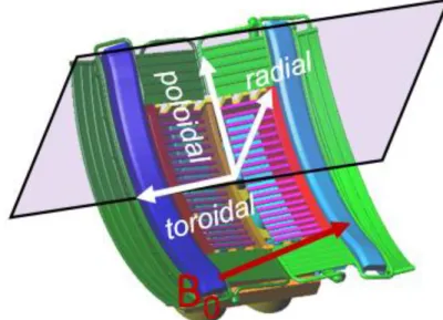
To describe the particle and current motion inside a Tokamak, two right-handed coordinate systems are often used at the same time, see Figure 1.4. The cylindrical coordinate system (R, , Z) is used to describe the overall framework. Here R represents the major radial direction, represents the toroidal direction, Z is the vertical direction. R0 is the major radius. Since the Tokamak geometry is toroidal homogeneous, one could take a poloidal cross-section in one toroidal position. In this cross-section plane, a second coordinate system, the poloidal coordinate system (r, , ) is often used. Here r represents the minor radial direction and represents the poloidal direction. ro is the minor radius. In this thesis, unless being specified, the radial direction means the major radial direction R.
5
Figure 1.4. A schematic view of the Tokamak coordinate systems
Tokamaks are designed to generate a magnetic configuration that can confine the plasma. The main magnetic field is along the toroidal direction and it is produced by the toroidal magnetic field coils, see Figure 1.3. However, the toroidal magnetic field alone is not enough to confine the plasma. This is because there are always some transversal (w.r.t the toroidal magnetic field) plasma drifts occurring due to the presence of curved field lines, which introduces a pressure or current gradient. In order to balance this gradient force, a poloidal magnetic field is needed as well.
Figure 1.5. Magnetic flux surface in the central plasma, view inside a poloidal cross section. Red curve indicates a typical profile of the plasma density; The blue curve represents the magnetic field
profile.
In a Tokamak, the poloidal magnetic field is generated by the plasma current. The plasma current is mainly induced by a central transformer, although there are some alternative current generation methods that will be presented later. The total magnetic field lines in a Tokamak therefore are helical. If one tracks their trajectories, they actually form many stratified surfaces. The field lines lay on these nested magnetic surfaces. Draw in a poloidal cross-section, it is something like many loops circling around the center, shown in Figure 1.5. The plasma parameters, i.e. density, pressure, are constant on the magnetic flux surfaces as a consequence of the plasma equilibrium [Grad 1958][Shafranov 1966]. Along the radial directions, the plasma parameters evolve as crossing the magnetic surface. A typical density profile and
6
magnetic field profile are shown in Figure 1.5. The magnetic field strength roughly scales as 1/R, with R the major radius axis.
Some additional coils are needed to control the plasma shape and position, i.e. the outer poloidal magnetic field coils. For convenience, in Tokamak convention, we also define the parallel direction to be the direction parallel to the confinement magnetic field B0. Similarly, the perpendicular direction is the
direction perpendicular to B0.
Tokamak can achieve a significant longer energy confinement time than the lasers. A typical set of parameters in a Tokamak that fulfilling the ignition conditions is:
n
10
20m T
3,
10
keV
and
E
3
s
. Compare to the air (n=1026 m-3, T=300K), the Tokamak plasma is rather tenuous and hot.Over the past 60 years, the Tokamak concept has been tried in many countries around the world. There are hundreds of them in total. The major limitations of the Tokamak concept are the following: at first, Tokamak relies on a strong magnetic field (several Teslas) to confine the plasma. The magnetic field is generated by currents flowing through the compactly winded magnetic field coils. An ordinary coil could produce huge heat which needs much energy to cool down. In 1988, people in France employed superconducting coils and built the world’s first supra-conducting toroidal coil Tokamak, Tore Supra. The temperature gradient formed between the central hot plasma (10 KeV) and liquid helium (3.4×10⁻⁴ eV) used in the superconducting coil is the greatest in the universe. Secondly, Tokamak usually operates in a pulsed mode. This is because the central transformer needs to generate a time-varying magnetic field in order to drive Ohmic plasma current. Once the central transformer current reach its maximum, the pulse will cease. A method to increase the pulse duration is by taking advantage of the non-inductive current. This is one of the applications of the auxiliary heating that will be discussed in section 1.5 .
Table 1-1. Typical parameters for Tore Supra Tokamak and ITER Tokamak
Tore Supra ITER
Major radius R0 (m) 2.5 6.2 Minor radius r0 (m) 0.7 2 Plasma toroidal current (MA) 1.5 15 Magnetic field B0 (T) 3.8 5.3
Another type of machine also using magnetic confinement, the Stellarator [Nuehrenberg 1995], was developed in parallel to the Tokamak. The main advantage of this machine is that it has no net current flowing along the toroidal direction. Consequently, there is no need to have a central transformer and the twisted magnetic field lines are totally created by the external helical coils. It is naturally a good candidate for a steady-state operation. It can also avoid plasma instabilities caused by the current gradient. However, since it relies on extremely dedicated magnetic configuration to balance the gradient force, the manufacturing of such a magnetic coil system is much more complicated than the coils used in Tokamak. In addition, it suffers from a low confinement performance and critical particle losses. Wendelstein 7-X, the world’s largest stellarator has just completed its 10 years’ construction phase and had its first plasma at the end of 2015.
At the moment, Europe has chosen the magnetic confinement as its main route to fusion power. The International Thermonuclear Experiment Reactor (ITER) - the largest Tokamak in the world and the leading
7
fusion machine, is currently being built in Cadarache, France. It has an ambitious scientific object: demonstrate the feasibility of fusion power and pave the path for the future commercial fusion reactor. Some major parameters of the Tore Supra Tokamak and the ITER Tokamak are shown in Table 1-1.
1.3
At the magnetized plasma edge: the Scrape-Off Layer
The central plasma is the useful part where the nuclear fusion reaction occurs. But one cannot have only the central plasma because the plasma cannot be of infinite size. This is also because one of the main products in DT reaction, helium and other impurity particles (also called as fusion ashes) must be exhausted from the fusion device at the edge in order to avoid plasma dilution. In addition, the output power must be exhausted from the plasma at the edge. Here the edge is defined where the plasma can have interactions with the wall. Unlike in the central plasma, at the edge, the magnetic field lines are open and connect to the wall or other protruding components. The boundary between the closed magnetic flux surface and open magnetic flux is called the Separatrix or the last closed flux surface (LCFS). In the earlier days, a solid surface called limiter was used to interrupt the magnetic field surface. The location of the limiter thus determines the LCFS. In this case, the limiter can be a source of impurity to the plasma because of the sputtering of the limiter surface. Modern-day Tokamaks are more often equipped with an element called “Divertor”. The Divertor is usually located at the bottom (in Figure 1.6) or at the top of the machine, it is further away from the plasma, compared to a limiter. In a Divertor configuration, the LCFS is solely determined by the magnetic field and its location is manipulable by changing the current in the Divertor’s magnetic field coils. Magnetic field lines connect to the Divertor target plates. The fusion ashes are diverted along the open magnetic field lines to the Divertor and then they are being pumped out of the machine.
Figure 1.6. Magnetic flux surface in JET Tokamak
What we called as edge in the beginning of this section is the region between the Separatrix and vessel wall. A more definitive name for this region is the scrape-off layer (SOL). It is marked in yellow in Figure
8
1.6. The SOL region is important, because it is the region where the plasma-wall interaction occurs. Understanding the plasma-wall interaction is one of the key tasks in magnetic confinement fusion research. Firstly, as indicated before, the fusion ashes and a part of fusion power must be exhausted through the plasma-wall interaction. Secondly, the plasma-wall interaction affects significantly the plasma confinement at the center. For example, the impurity generated at the edge can be transported to the center, which can reduce the energy confinement time and drop down the temperature.
Therefore, before thinking of making any nuclear reaction, one needs to have a clear view of what is happening at SOL.
1.4
Plasma-wall interactions at the SOL
Many physical processes are occurring at the SOL region. A dedicated study of plasma-wall interaction will cover material science, plasma physics, atomic physics, chemistry, mechanics, et al. Some references dedicated on this topic can be found in [Kirschner 2009][Meade 1974][Reiter 1991][Stangeby 2000]. Here we just mention a few of them that are related to this thesis,
Plasma facing material erosion and re-deposition: During Tokamak operation, plasma facing components suffer constantly high energetic particle flows striking on their surface. This could cause some erosion processes, i.e. sputtering, melting, sublimation and evaporation. Fortunately, a large part of material components released to the plasma by erosion are re-deposited again on the wall surface. This re-deposition process can largely compensate the loss of surface material by erosion.
Sheath excitation: The plasma potential is often positively biased compared to the grounded wall. A thin layer called sheath is formed at the plasma/wall interface. Inside the sheath, the plasma charge neutrality is broken and ions get accelerated. High energy ions then bombard the wall which can cause many deleterious effects, i.e. hot spots at the plasma facing components, impurity production and edge power losses. Understanding the reason of sheath excitation and its effect is the main topic of this thesis. Sputtering and heat loads: Sputtering is the ejection of the particles from the surface of a solid caused by the bombardment of highly energetic particles, i.e. ions accelerated by sheath. Sputtering can be categorized as physical sputtering and chemical sputtering. For physical sputtering, there is generally an energy threshold below which the sputtering does not occur. High Z material usually has a significant larger energy threshold. For deuterium incident, the energy threshold for Carbon and Tungsten surfaces are 30eV and 214eV [Kirschner 2015], respectively. The sputtering yield is defined as the number of particles being ejected from the surface per incident ion. It is a function of the incident ion energy, the mass ratio between the projectile and target and the surface binding energy of the target particles. A Deuterium plasma with a temperature of 100eV has a sputtering yield of 0.1% for a Tungsten surface and 2% for a Carbon surface [Samm 2015]. The former material has been chosen as the armor of the ITER Divertor. During the ITER operation, it is estimated that the Divertor will suffer around 5-20MW/m2 steady-state heat flux and 1GW/m2 instant heat flux [Linke 2015]. As a comparison, the heat flux density at the nozzle of rocket is just around 85MW/m2. Heat loads on other plasma facing components are less pronounced, but still could produce serious damage on the wall surface.
Impurity transport and radiation: as highly energetic particles incident on the surface, some wall materials can be released to the plasma. They are usually different from the plasma species and thus play as impurities. Some high Z (atomic number) impurities, like Tungsten can be transported to the core plasma and significantly cool down the plasma core by its radiation losses. In some worse cases, it can
9
further develop instabilities, so called MARFE [Lipschultz 1987] and cause plasma disruptions [Schuller 1995].
1.5
Heating and current drive methods in the magnetic confinement device
1.5.1 Ohmic heating
Once the plasma is created, the ions and electrons are driven by the loop voltage which is produced by the central transformer. They flow along the magnetic field and form a plasma current. In a Tokamak, this current can easily reach several Mega Ampere. The plasma has an electrical conductivity. In the parallel direction, it is expressed by Spitzer conductivity,
3/2 //, 9 (0.001 ) 1.65 10 ln S Te
(1.7)Where Te is the electron temperature in eV, ln is the Coulomb logarithm whose typical values are between 15 and 20. From Eq. (1.7), the conductivity increases with the electron temperature. So the resistivity and thus the efficiency of Ohmic heating decreases dramatically after the temperature reaches 2.6-3.5107 KeV. In order to achieve the ignition temperature, e.g. T=10 KeV, additional heating is needed. There are two major auxiliary heating methods, neutral beam injection and radio frequency (RF) wave.
It’s worthwhile to mention that besides providing additional heating, another main purpose of the auxiliary heating is to drive non-inductive current. As indicated before, one of the drawbacks of Tokamak operation is that it is intrinsically pulsed. However, in a real fusion reactor, a steady-state operation is desired for many reasons. This relies on the contribution of non-inductive currents to the total plasma current. A steady state operation of Tokamak requires at least 20% of the total current driven from auxiliary heating & current drive. For ITER, a high fraction of it will come from the bootstrap current [Peeters 2000], which is a naturally occurring current caused by the pressure gradient. Another part will come from the auxiliary heating being discussed in the following.
1.5.2 Neutral beam injection
In a Tokamak plasma, the magnetic field is so strong that any charged particles coming from outside will soon be deflected by the Lorentz force and could not reach the core. In order to heat the core plasma, one can only use neutrals. The structure of a neutral beam system is the following: ions (typically H+ or D+) coming out from an ion source are accelerated by electrical grids to highly energetic (100 keV at present) and then they pass through a cold neutral gas where they are neutralized by charge exchange. The remaining ions that have not been neutralized are diverted out by a magnetic field. Finally only the neutral hydrogen atoms are injected into the plasma. Inside the plasmas, the neutrals are ionized again soon (with a typical penetration length of 1m) and then transfer their energy to the plasma through collisions. Neutral beam injection has achieved significant heating in present-days’ Tokamak experiments and it is the main heating system in JET and DIII-D Tokamaks. Some references about this heating method can be found in [Hemswoth 2009][McAdams 2014]. In the following sections, we will only talk about the radio frequency wave heating.
1.5.3
Radio frequency wave heating and current drive
The electromagnetic waves are injected through the Tokamak edge. In most media, i.e. water inside food, waves are damped through collisional mechanisms. In fusion plasmas, however, collisions are often too weak so it has to rely on the collisionless mechanism. When the wave frequency matches one of the
10
cyclotron frequencies, the corresponding charged particle is then accelerated by the oscillating electric field of the wave in the perpendicular direction. Thus the wave energy and momentum could be transferred from the wave to the charged particles. This is the fundamental principle of the so called resonant heating. In the parallel direction, the wave can also be damped through a collisionless mechanism called Landau damping [Landau 1946][Chen 2016]. The thermal velocity of the particles usually follows a distribution, e.g. Maxwellian distribution. Those particles whose thermal velocity are smaller than the wave phase velocity can be accelerated by the wave. On the contrary, the other particles having a velocity larger than the wave phase velocity will be slowed down. If the wave velocity lies on the higher part of the velocity distribution, the particles will then feel a net acceleration. Assuming a plane wave with harmonic oscillations in exp(𝑖𝑤𝑡 − 𝑖𝐤 ∙ 𝐫). (Note: here we used the engineering convention, as it will be in the rest of this thesis). The above two heating mechanisms are governed by the wave-particle resonance condition,
// //s cs
0
w k v
Nw
(1.8)Where wis the angular frequency, k// the wave vector parallel to the confinement magnetic field, v//s parallel velocity of particle species s, wcs is the cyclotron frequency of s, N is an integer, represents the order of the harmonic.
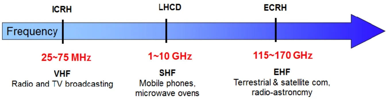
Depending on the frequency, waves can be categorized as the ion cyclotron range of frequency (ICRF)
wave frequency 50
2 w
f
MHz , lower hybrid (LH)f
2
GHz
and electron cyclotron range of frequency (ECRF)f
100
GHz
, see Figure 1.7. The ICRF and ECRF waves, as indicated by their names, are damped at the ion cyclotron resonance and the electron cyclotron resonance, respectively.Although the electromagnetic waves carries negligible momentum, it could achieve current drive by heating particles in one specific direction. The particles that are heated become less collisional than those who are travelling in the opposite direction. Thus a net current is formed. This is the principle of the RF wave current drive.
The lower hybrid wave is generally the most efficient auxiliary method for non-inductive current drive in present-day Tokamak, while the electron cyclotron wave is an ideal tool to provide localized current drive and heating. Some reference about these two waves can be found in [Hoang 2009][Goniche 2013][Prater 2004]. The following text will only focus on the ion cyclotron wave.
11
Finally, a list of auxiliary heating powers equipped in the Tore Supra and ITER is shown in Table 1-2. Table 1-2. Quantities of the auxiliary heating power in Tore Supra and ITER Tokamak
Auxiliary heating power
Tore Supra ITER
ICRH (MW) 12 20
LHCD (MW) 7 0
ECRH (MW) 0.8 20
NBI (MW) 0.5 33
1.6
Ion Cyclotron Resonant Heating: an efficient way to achieve direct ion heating
Among these three wave types, the lower hybrid and electron cyclotron wave mainly damp their waves directly on the electrons (although it can also indirectly heat ions through collisions). However, the fuel of the nuclear reaction is a mixed of Deuterium and Tritium ions. It will be more efficient if one can heat these two nuclei directly. This is where one of the key elements related to this thesis comes into the game: the Ion Cyclotron Resonant Heating (ICRH). At first let us describe the principles of ICRH and its operation scenarios.
A schematic view of ICRH antenna in the WEST (Tungsten (W) Environment in Steay-State Tokamak) tokamak is shown in Figure 1.8. WEST is the upgraded version of Tore Supra Tokamak at CEA, which aims at testing actively cooled tungsten divertor. The waves are launched by phased array straps (antenna) at the edge. For ICRH (𝑓=25-100MHz), two types of waves could be excited: the fast wave (FW) and the slow wave (SW), named by the relative scales of their phase velocities. The fast wave can propagates across the whole plasma and thus it is the main heating wave. The ICRH antenna is designed for exciting this wave. The slow wave is excited parasitically by the antenna and it is widely blamed for causing some deleterious wave-SOL interaction, i.e. radio frequency sheath that will be introduced in the next section.
Figure 1.8. The WEST Tokamak vacuum vessel and ICRH antenna. Note: the ICRH antenna here does not reflect the final design that will be used actually in WEST
ICRH has a variety of heating scenarios and relatively cheaper to build, making it a very popular auxiliary heating method. Here are some of its main heating scenarios,
Wave absorption at the fundamental resonant frequency (N=1): This looks like the most straightforward way to have ion heating. Observing along the direction of the magnetic field, the
12
ions rotate left-handedly along the magnetic field line. If an incident wave having the same polarization and the same frequency as ion cyclotron motion, then the oscillating electric field of the wave is in phase with the ion motion. Over one cyclotron period, the ions feel a net acceleration. But this is not going to happen in single-ion-species plasma. This is because the fast wave is right-handed at the fundamental resonance of ions, see chapter 2, section 2.1.4. Wave absorption at the harmonic frequency (N>1): The polarization problem can be avoided by
working at the harmonics of the cyclotron frequency. Let’s take N=2 for example. The wave electric field varies two times faster than the ion cyclotron frequency. If the wave electric field is uniform, then there is no net acceleration for ions. On the contrary, if the wave electric field is higher on one side than the other side, then the ions experience a net acceleration over one period. Similarly, higher harmonic resonant heating requires the existence of non-vanishing higher derivatives of the electric field. The efficiency of harmonic wave heating decreases with harmonic number.
Minority heating: Another way to avoid the polarization problem is to use multiple ion species. For example, put a small amount of hydrogen in a majority of deuterium plasma. The polarization is determined by deuterium but the wave is damped at the fundamental hydrogen resonance. In this case, the fast wave has a left-hand electric component and thus could heat the hydrogen ions, which then transfer their energy to other majority deuterium particles, or electrons through collisions.
Mode-conversion can take place if several ion species co-exist in the plasma. Each of two ion species pair could create an ion-ion hybrid resonance. The fast wave is mode converted to other waves, i.e. ion Bernstein wave at this resonance. The converted waves are damped on the electrons through Landau damping. A further details of this mechanism can be found in [Lu 2013]
Most of the present-day Tokamaks use the minority heating as the main ICRH heating scenario. ITER will use the second harmonic of Tritium and 3He minority heating.
Figure 1.9. 4 straps ICRH antenna in the KSTAR Tokamak (left); 2 straps ICRH antenna in the ASDEX-Upgrade Tokamak (right)
Different ICRH antennas have been used in many machines. But all of them have some features in common. Firstly, the straps are placed along poloidal direction. This is because the wave that is expected to be excited by the straps has a large poloidal electric field. Secondly, in order to have different spectra
13
for multiple purposes, the antenna usually contains multiple straps with different phasings. Thirdly, the antenna includes some protecting components, like side limiters and one Faraday Screen. The Faraday screen also aims at minimizing the parallel electric field. An example of ICRH antenna in the ASDEX-Upgrade and the KSTAR Tokamak are shown in Figure 1.9.
1.7
Overview of ICRH wave launchers on the Tore Supra Tokamak
The ICRH system in Tore Supra Tokamak is designed for 12MW of ICRH power injection in the frequency range of 35 to 80MHz (ion-ion hybrid heating) and 8MW at 120MHz (harmonic cyclotron heating). The power is delivered into Tokamak through three horizontal ports. The total ICRH system thus consists of three wave launchers (4MW per each), six transmission line and six RF generators. Each of the six RF power generators consists of a pilot generator, a modulator, a solid state wideband amplifier and a 3-stage tetrode amplifier. Six 80m long coaxial transmission lines are installed from the generator to the torus hall. They have a diameter of 140/230mm, with a characteristic impedance of 30Ω. Each of the generator and transmission line connects one strap. More references on the transmission line and generator can be found in [Kuus 1988].
Figure 1.10. Layout of the standard ICRH wave launcher on Tore Supra, cite from [Vulliez 2003] A cross-section of one of the three wave launchers is shown in Figure 1.10. It is about 3m’s long in reality. Each of the three wave launchers has two radiating straps (placed side by side in toroidal direction) which are protected by Faraday screen in front of it and lateral bumpers in the poloidal directions. Each radiating strap is based on the resonant double loop concept [Owens 1985]. It is fed at the middle and short-circuited at both ends through two tuning capacitors, which creates a one wave resonator [Colas 2006]. The strap has a large self-inductance, the AC current flowing on its surface varies in time. This is not a lossless resonance loop since it radiates RF waves to the plasma. The energy loss is compensated by the feeder. During the plasma pulse, the plasma resistance (especially the capacitance) is time-varying, the matching is done by changing the capacitance of the resonant circuit. The two capacitors are connected side by side through a bridge. The capacitor consists of two parallel plates, the amount of plate surface which overlaps are controlled by the mechanical tuning bars, i.e. the pink ones in Figure 1.10. A quarter-wavelength stub is used at the input of the wave launcher to enable the cooling water cycling through the wave launcher. The port flange connects the vessel port and the wave launcher. During the
14
operation, the part in front of port range of the wave launch is plugged into the vacuum vessel of the Tokamak. The antenna is hanging on a rollerskate, which allows the antenna moving radially about 10cm along the port axis during Tokamak pulses to achieve more power being transmitted to the plasma.
Figure 1.11 is a picture of the plasma facing part of the ICRH antenna. The classical ToreSupra ICRH antenna [Beaumont 1988] consists of two vertically placed, water cooled rectangular straps made of silver-coated stainless steel, shown in brown. The currents flow along the straps and thus excite mainly the poloidal electric fields, see Figure 1.12. The Tore Supra classical antenna uses two straps. Just like the antenna array used in telecommunication, the direction of emitted wave is determined by the current phasing on the straps. Usually, three current phasings are often used. Dipole phasing [0 π] and monopole phasing [0 0] have antiparallel and parallel currents, respectively. They are frequently used as heating phasings, while the asymmetric phasing [0 π/2] is used mostly for current drive purposes.
Figure 1.11. ICRH antenna on Tore Supra (view from the plasma side)
Figure 1.12. The principle of exciting RF field by a poloidal current
The metallic frame with many tilted bars in front of the straps is the Faraday screen. Its dimension is 0.432*0.595 m2. The bars are oriented roughly parallel to B
0. Initially it is designed to cancel the parallel
electric field of the wave and protect the straps from heat flux. The Faraday screen is actively cooled by pressurized water at 150oC behind it and it is coated with boron carbide (B
4C) to limit high Z impurity contamination of the plasma. The two straps are separated by a vertical septum in the middle. At their lateral sides, a curved structure sitting at each side of the antenna is called side limiter. Its main role is to protect the antenna from the heat flux coming from toroidal directions. Like all the other plasma facing components, it is cooled by a water loop beneath it. The side limiter is made of CuCrZr alloy.
1.8
Selected ICRH challenges
Despite the fact that ICRH has many flexible heating schemes and the engineering system is generally reliable during the Tokamak operation, it has some defects which limit its performance. The requirement that a fusion reactor should work in a continuous way imposes a big challenge for the heating system. One must thus optimize the antenna-plasma coupling in a steady-state operation, in the meantime avoiding the spurious effects such as impurity generation, hot spots and anomalous edge heating. Besides, the interactions between different heating systems also need to be accounted for. Here we list several of the main issues related to this thesis.
![Figure 1.10. Layout of the standard ICRH wave launcher on Tore Supra, cite from [Vulliez 2003]](https://thumb-eu.123doks.com/thumbv2/123doknet/14611417.732498/31.918.142.731.451.724/figure-layout-standard-icrh-launcher-tore-supra-vulliez.webp)
![Figure 1.14. A photograph of Aline vacuum chamber without magnetic field coils, cite from [Faudot 2015]](https://thumb-eu.123doks.com/thumbv2/123doknet/14611417.732498/35.918.138.823.317.605/figure-photograph-aline-vacuum-chamber-magnetic-field-faudot.webp)


![Figure 2.18. Left: Measurement from retarding field analyzer in Tore Supra, cite from [Kubic 2013]](https://thumb-eu.123doks.com/thumbv2/123doknet/14611417.732498/70.918.118.793.646.949/figure-left-measurement-retarding-field-analyzer-supra-kubic.webp)