HAL Id: hal-02614510
https://hal-amu.archives-ouvertes.fr/hal-02614510
Submitted on 21 May 2020
HAL is a multi-disciplinary open access
archive for the deposit and dissemination of
sci-entific research documents, whether they are
pub-lished or not. The documents may come from
teaching and research institutions in France or
abroad, or from public or private research centers.
L’archive ouverte pluridisciplinaire HAL, est
destinée au dépôt et à la diffusion de documents
scientifiques de niveau recherche, publiés ou non,
émanant des établissements d’enseignement et de
recherche français ou étrangers, des laboratoires
publics ou privés.
Control Strategies for Tidal Stream Turbine Systems - A
Comparative Study of ADRC, PI, and High-Order
Sliding Mode Controls
Zhibin Zhou, Seifeddine Ben Elghali, Mohamed Benbouzid, Yassine Amirat,
Elhoussin Elbouchikhi, Gilles Feld
To cite this version:
Zhibin Zhou, Seifeddine Ben Elghali, Mohamed Benbouzid, Yassine Amirat, Elhoussin Elbouchikhi,
et al.. Control Strategies for Tidal Stream Turbine Systems - A Comparative Study of ADRC, PI, and
High-Order Sliding Mode Controls. IECON 2019 - 45th Annual Conference of the IEEE Industrial
Electronics Society, Oct 2019, Lisbon, France. pp.6981-6986, �10.1109/IECON.2019.8927629�.
�hal-02614510�
Control Strategies for Tidal Stream Turbine Systems –
A Comparative Study of ADRC, PI, and High-Order
Sliding Mode Controls
Zhibin Zhou
1, Seifeddine Ben Elghali
2, Mohamed Benbouzid
3,4, Yassine Amirat
1, Elhoussin Elbouchikhi
1, Gilles Feld
11ISEN Yncréa Ouest, UMR CNRS 6027 IRDL, Brest, France 2Aix-Marseille University, UMR CNRS 7020 LIS, Marseille, France
3University of Brest, UMR CNRS 6027 IRDL, Brest, France 4Shanghai Maritime University, Shanghai, China
Email: [email protected], [email protected], [email protected], [email protected], [email protected], [email protected]
Abstract—Due to the characteristics of predictability and high energy density in tidal current resources, tidal stream turbine generation systems have been developed in the last decades around the world. Speed control would be necessary to perform the maximum power point tracking (MPPT) task under varying marine current conditions. Considering that various disturbances or parameter uncertainties may deteriorate the system performance, the active disturbance rejection control (ADRC) strategy seems to be an interesting solution for controller designs. In this paper, an ADRC strategy is applied in the speed control loop for realizing MPPT under disturbances of current velocity and turbine torque. The system performance of the proposed ADRC is compared with PI and high-order sliding mode (HOSM) control strategies. The operation under swell wave disturbance is also carried out. This simulation-based comparative study shows the effectiveness and advantages of the ADRC controller over conventional PI controller in terms of quick convergence, overshoots elimination, and better performance under disturbances.
Keywords—Tidal stream turbine, disturbance rejection control, maximum power point tracking, speed control.
I.INTRODUCTION
Main advantages of marine current energy are related to the predictability in hourly time scale and a high energy density [1]. Tidal stream turbine (TST) generation systems, based on similar principles of wind turbine technologies, have been developed to harness the kinetic energy from tidal-driven marine currents [2]. In the last decade, various demonstrative TST projects have been successfully industrialized. Although challenges such as submarine installation and maintenance do exit, TST generation systems are still thought to be a promising power supplying solution for some remote islands or coastal areas [3-4]. For achieving compact structure and reducing maintenance requirements, several TST projects adopt turbines with fixed-pitch blades and choose permanent magnet synchronous generator (PMSG).
TST system is expected to extract maximum power from the marine tidal current flow. The power harnessed is proportional to cubic marine current velocity and the turbine power coefficient. For a turbine with fixed-pitch blades, the turbine power coefficient (Cp) mainly depends on tip speed
ratio (TSR), which can be controlled by the generator rotational speed. Therefore, speed control in TST generation system could be necessary in order to capture maximum power under varying marine current conditions. A previous study in [5] shows that under strong swell wave disturbances, a speed control with filter-based reference or a torque-based control can achieve smoother power produced. However, in that work only classical proportional-integral (PI) controllers are used and other kind of disturbances such as sudden current flow speed change and unpredictable turbine mechanical torque changes are not considered.
Although PID control is the most popular control strategy in the industrial applications due to its simple structure and relative easy parameter tuning, it may suffer several drawbacks such as: 1) the controller implementation is often without the derivative part (D) due to the noise sensitivity; 2) low response or saturation caused by the integration behavior; 3) controller parameter tuning usually requires accurate plant model and parameters which may be unavailable or present uncertainties and viable values under different operation conditions. The researchers in [6-8] proposed a controller design strategy called active disturbance rejection control (ADRC) to be an alternative control paradigm of PID control. The key characteristic of ADRC is that all kinds of disturbances including external/internal disturbances, linear/non-linear disturbances, and constant/time-varying disturbances are treated as a generalized “total disturbance” which can be estimated by a non-linear state observer and then be compensated in the control signal. The non-linear control law of ADRC presents advantages of not requiring accurate plant parameters and effective disturbance rejection with a not too complicated observer structure.
In this paper, the ADRC strategy is applied in the speed control of a TST generation system for realizing MPPT task under disturbances and its performance is compared with PI and high-order sliding mode (HOSM) controls. In Section II, the design and parameter tuning of the three controllers (PI, ADRC and HOSM) for the speed control of the TST generation system are presented. In Section III, the simulation results of the three strategies under disturbances of tidal current speed and turbine torque are compared. The performances of energy production under swell effect are also presented.
II. SPEED CONTROL FOR A TSTSYSTEM
The mechanical power extracted by a horizontal-axis TST can be calculated by the following equation.
2 31
ρ π
2 p tide
P C R V (1) In (1), the seawater density ρ and the turbine radius R are constants; Vtide is the velocity of marine tidal current; Cp is the
turbine power coefficient. For a given turbine, the Cp curve
may be approximated as a function of the pitch angle and the tip speed ratio . The considered TST is a fixed-pitch blade one, therefore Cp depends only of . For typical MCT
prototypes, the optimal Cp value is estimated to be in the
range of 0.39-0.45 [3].
Figure 1 shows the Cp curve used in this work. The
maximum Cp value is 0.41, which corresponds to a tip speed
ratio of 6.3. This value is considered as the optimal tip speed ratio (λopt) for obtaining the maximal Cp value under varying
tidal current conditions.
A basic MPPT control can be realized by the speed control of the associated generator to regulate the turbine rotational speed according to tidal current velocity. Considering the existence of a gearbox between the low-speed turbine and high-low-speed generator (with a low-speed ratio
Ngear), the speed reference for the generator can be given as follows: opt tide m gear V N R (2)
Fig. 1. Cp curve of the studied TST.
Fig. 2. General control scheme for a PMSG-based TST system.
For the PMSG, the d-q frame model is described by the following equations. s e s e e m e p m m m e B m d ω dt d ω ω ψ dt 3 ψ ( t ) 2 d d d d d d q q q q q q q d d q d d q i v R i L L i i v R i L L i T n i L L i i J T T f (3)
In (3), vd, vq and id, iq are stator voltages and currents in
the d-q axis respectively; Rs is the stator resistance; Ld, Lq are
inductances in the d-q axis (Ld = Lq = Ls for a non-salient
machine is considered in this work); ωe, ωm are machine
electrical and mechanical speed; Te , Tm are respectively the
machine electro-magnetic torque and the mechanical torque;
np is the generator pole pair number; ψm is the flux linkage
created by the rotor permanent magnets; J is the total system inertia and fB is the friction coefficient associated to the
mechanical drivetrain. The generator parameters can be found in the Appendix.
Based on the PMSG model, a double-loop control schema with inner current control loop and outer loop speed control is popularly adopted as shown in Fig. 2. In this control schema, the speed controller will be focused in this work. The current response is much faster than the speed response and the current controller tuning is usually easier than the speed controller. Therefore, PI controllers are applied for the two current loop in the following parts and then the three different control strategies – PI, ADRC and sliding mode control will be applied to the speed control.
A. Proportional-Integral Control
Since the PI current controllers for controlling d and q axis currents will not change in this work and should be tuned before the speed controller, the tuning of the two PI controllers shown in Fig. 2 is to be presented firstly. Same parameters can be used for these two PI controllers due to the similar dynamics for id and iq loops. The open-loop transfer function of the PI
control based current loop can be expressed as:
0 ( 1) 1/ ( ) ( / ) 1 1 p i s i s s i K s R G s s L R s T s (4) with Kp and Ki 1/ias controller gains and Ti(which ismuch smaller than the electrical time constant Ls/Rs) as a
small time constant standing for current sensor and power converter delays. Based on the dominant pole cancelation method and with a desired damping factor (0.707 in this work) for the close-loop transfer function, the following controller gains can be chosen for the current-loop PI controllers:
/ 2 i s s p s i i K R L K R T K (5) 6852The speed controller will generate the q-axis current reference iq
according to the speed tracking error. The d-axis
current reference id
is usually set to 0 for maximizing the electromagnetic torque. The PI speed controller parameters can be tuned by many ways, and in this work the non-symmetrical optimum method (NSOM) is chosen. As one analytical method, the NSOM relies on a second-order approximated model of the plant with a generalized time constant (TQ1 /Q), which includes all the time delays in the speed loop, and KQ, which represents the slope rate of
open-loop step response. These two parameters can be deduced from a simple step response test in simulation or in real system. Using the NSOM, the parameters of the PI speed controller can be obtained from [9] as follows:
Q ps c Q c Q is c K K K (6) In (6), the correcting gain fact γc is defined in terms of the
desired resonant peak value Mc ; the parameter αc is calculated
by a phase advance Δφ, which depends on γc. More details of
the NSOM tuning procedure can be found in [10].
B. Active Disturbance Rejection Speed Control
In this part, the alternative controller design using ADRC strategy is applied to the speed controller. From the PI speed controller tuning procedure presented above, it can be found that PI controller tuning relays on the knowledge of plant parameters or requires some tests to obtain an approximate plant model. However, no disturbances or non-linear dynamics is considered in PI controller designs and this may cause poor performance in a real system.
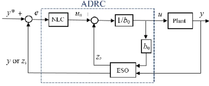
To overcome these drawbacks, ADRC uses a non-linear control law (NLC) with an extended state observer (ESO) to have fast convergence speed and effective disturbance rejection capability. A stand formulation for applying ADRC is based on a canonical state-space expression of the plant with the unknown disturbances as an extended state variable. The order of ADRC controller depends on the derivative order of the controlled variable [7], [11]. Supposing the first-order derivation of the controlled plant output y can be formulated by
1 1 x F b u y x (7)
In (7), u is the plant input, b is a constant, and F represents the total disturbance (which combines all the known dynamics and unknown disturbances). Then, F is treated as an extended state variable x2 to be estimated by the ESO. The basic controller
diagram is illustrated in Fig. 3. In this figure, e is the tracking error; b0 is a roughly estimated value of the constant b of the
plant described in (7); and the ESO has two outputs: z1 is the
estimation of the plant output y; and z2 is the estimated total
disturbance F.
Fig. 3. First-order ADRC control diagram.
For the speed controller design for a TST system, the variable to be controlled is the generator rotor speed ym, and the controller output is the q-axis current reference u =iq
. Based
on the PMSG model, the following equation can be obtained 1.5 ( m B m) p m m q n T f i J J J (8) Applying ADRC does not need accurate system parameters, which means that the unknown disturbances or variations of the mechanical torque, friction coefficient, rotational speed and the system inertia can be generalized as the total disturbance and estimated by the ESO. The constant
b0 is set close to or equal to b1.5npm/J.
The nonlinear function called fal is applied in the ADRC,
1 sign( ), ( , , ) , x x x fal x x x (9)
with x as the main input representing some kind of error information; 0 < α < 1 enables the function value to have a reducing effect with large x input (this character is important to avoid controller saturation) and δ > 0 introduces a linear zone for avoiding too big function value for small x around 0. The ESO of the ADRC can then be constructed as
1 1 1 2 0 1 1 2 2 2 , , , , m z y z z z b u fal z fal (10)The NLC is given as u0 k fal e1 ( , 0, ), and the ADRC controller output is u
u0z2
/b0 . iqThe ESO gains β1, β2 and the NLC gain k1 might be tuned
based on the control system sampling time (h =0.01 ms is considered in this work) and not on system parameters. In this paper, these controller gains are tuned as
1 2/5 2 2/5 1
6 1 1
, ,
5h h k h
(11)
Other controller parameters are set as δ = 0.1, α0 = 0.3, α1 =
C. High-Order Sliding Mode Speed Control
HOSM is another interesting nonlinear robust control strategy that has been already successfully applied for TST systems handling heavy nonlinearity and parameter variations [12-14]. For the TST generation system speed controller, the sliding surface can be defined as the speed tracking error
1 m m
s e (12) and the HOSM controller output in this work is calculated by
0.5 1 1 sign 1 2 sign 1 q u i K s s K s
(13) The controller gains K1 and K2 may be tuned by trial anderror observing via simulation, and in this paper K1 = 3 and
K2 = 30 are chosen for a good compromise between fast
convergence and low output chattering. III. SIMULATION RESULTS
In this part, a laboratory-scaled PMSG (1.82 kW, 2000 rpm) is studied in the simulation. The detailed parameters of the simulated PMSG-based TST generation system can be found in Appendix. In the first part, sudden current velocity and turbine torque disturbances are studied and in the second part, the generator performance under swell-induced disturbance is compared by applying the three above-presented different speed controllers.
A. Under Disturbances of Current Velocity and Torque
In this part, the current velocity without disturbances is considered as a constant value of 2 m/s during the short period of 15 seconds. A sudden current velocity fall (with -0.7 m/s as the peak) is applied during 6 ~ 6.6 s, and a large turbine torque thrust of 12 Nm is added for 11~11.5 s. Because ADRC is relative new compared with PI and HOSM control strategies, the simulating results of its performance during the entire 15 s will be firstly illustrated and then detailed comparison will be carry-out in different time periods.
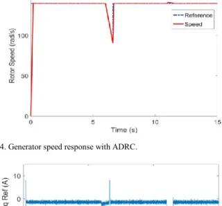
Figures 4 to 6 show the resulted generator speed, current and power. It can be seen from Fig. 4 that the generator speed response with ADRC control strategy converges to the speed reference calculated by MPPT very rapidly, and Fig. 5 demonstrates that the PI current controller is quite effective for regulating the current to the its reference given by the output of the speed controller. Figure 6 illustrates that the turbine mechanical power and generator electromagnetic power are very close at steady state and the small difference between the two powers is caused mainly by mechanical friction losses of the TST system. At starting stage and the speed velocity distance clearance time (6.6 s), the speed reference is a step rise and this causes large inversed generator torque and motor operation for satisfying the fast acceleration demand. These current/power peaks can be reduced by adding a speed reference filter.
In order to compare the ADRC performance with PI and HOSM strategies, smaller time scales should be used to show the differences during disturbances starting stage and periods; while the performances of the three controllers are very close at steady state.
Fig. 4. Generator speed response with ADRC.
Fig. 5. Generator q-axis current response with ADRC.
Fig. 6. Turbine and generator produced powers with ADRC.
Figure 7 compares the generator speed response during the starting stage. It can be observed that the PI controller leads to an overshoot of 7.4 rad/s, which is 5.3% of the steady state speed (139.5 rad/s). The HOSM controller enables to reduce the overshoot to 3% with a faster convergence speed; while the ARDC presents the shortest settle time with no overshoot. Figure 8 shows that, under the current velocity drop disturbance, all the three controllers are capable to follow a dropping speed reference. However, when the disturbance is cleared at 6.6 s, the speed reference has a step rise to its steady state value. In this case a 5% speed overshoot can be seen with the PI controller, while performances of both ARDC and HOSM controllers are very similar.
Fig. 7. Speed tracking comparison during starting stage.
Fig. 8. Speed tracking comparison during current velocity disturbance.
Figure 9 compares the performances under large torque disturbance. It illustrates that the sudden rise of the turbine mechanical torque at 11 s leads to a speed rising and the clearance of the disturbance at 11.5 s causes a speed dropping with the PI speed controller (the maximum speed tracking error is about 3.5%). The HOSM speed controller reduces the tracking error to 2.4% with faster recovering time. The ARDC achieves the smallest maximum tracking error about 1.5% and no speed drop error at the clearance of the disturbance. Figure 10 shows that ARDC can have a little smoother power during the torque disturbance.
B. Under Swell Waves Disturbance
Swell waves may propagate deeply under the sea surface and cause current velocity fluctuations for TST generation systems. Figure 11 shows the marine current speed fluctuations under swell effect in the simulation (after 4 s).
Fig. 9. Speed tracking comparison during torque disturbance.
Fig. 10. Generator power during torque disturbance.
Fig. 11. Marine current speed variations under swell effect.
Figures 12 and 13 illustrate the simulation results for the generator speed tracking performance and the produced electrical power with ADRC speed controller. It can be observed that ADRC speed controller realizes a very good speed tracking under swell-induced disturbance and the tracking errors are smaller than 0.1 rad/s. The power difference between the generator and the turbine (in Fig. 13) during acceleration/deceleration is not very large because the simulated TST system has a low system inertia. In fact, the speed tracking and power producing curves under swell effect with the other two speed controllers (the PI and HOSM) have not significant differences compared with ADRC, therefore only the simulation results with ADRC speed controller are presented. Figure 14 compares the energy production (calculated by the integration of generator power) during swell disturbance. At the end of the simulation (60 s), it can be observed that the energy yielding by a PI control is about 31.875 kJ; HOSM and ADRC lead to slightly better energy yielding with 31.887 kJ and 31.888 kJ, respectively.
Fig. 13. Generator power under swell disturbance (with ADRC).
Fig. 14. Energy production comparison.
IV. CONCLUSION
An active disturbance rejection speed controller was successfully applied to a tidal stream turbine generation system. The achieved simulation results confirm the effectiveness of this advanced and robust control strategy. Compared with PI and high-order sliding mode controls, ADRC presents faster convergence speed and smallest overshoot and tracking errors. However, due to a relative complex controller structure, ADRC suffers from a high computational cost. Indeed, it requires higher computational time for calculating the controller output compared to PI and HOSM strategies.
APPENDIX TSTSYSTEM PARAMETER LIST
Turbine blade radius 0.32 m Maximum Cp value 0.41 Optimal tip speed ratio for MPPT 6.3 Rated marine current speed 3.0 m/s Total system inertia 0.03 kg.m2
System friction coefficient 0.0035 Generator nominal power 1.82 kW Generator nominal torque 8.7 Nm DC-bus rated voltage 700 V Rotor nominal speed 2000 rpm (209.4 rad/s)
Pole pair number 3
Permanent magnet flux 0.5333 Wb Generator stator resistance 1.3 Ω Generator d-q axis inductance 13 mH Gearbox speed ratio 3.544
REFERENCES
[1] S. Benelghali, R. Balme, K. Le Saux, M. E. H. Benbouzid, et al., “A simulation model for the evaluation of the electrical power potential harnessed by a marine current turbine”, IEEE Journal of Oceanic
Engineering, vol. 32, no 4, pp.786-797, Oct. 2007.
[2] A.S. Bahaj, “Generating electricity from the oceans,” Renewable and
Sustainable Energy Review, vol. 15, n°7, pp.3399-3416, Sept. 2011.
[3] Z. Zhou, M.E.H. Benbouzid, J.F. Charpentier, F. Scuiller and T. Tang, “Developments in large marine current turbine technologies - A review,” Renewable and Sustainable Energy Reviews, vol. 77, pp. 852-858, May 2017.
[4] H. Chen, T. Tang, N. Aït-Ahmed, M. E. H. Benbouzid, M. Machmoum and M. E. Zaïm, "Attraction, Challenge and Current Status of Marine Current Energy," IEEE Access, vol. 6, pp. 12665-12685, 2018. [5] Z. Zhou, F. Scuiller, J.F. Charpentier, M.E.H. Benbouzid, and T. Tang,
“Power smoothing control in a grid-connected marine current turbine system for compensating swell effect,” IEEE Transactions on
Sustainable Energy, vol. 4, n°3, pp. 816-826, July 2013.
[6] Z. Gao, Y. Huang and J. Han, “An alternative paradigm for control system design,” in Proceedings of the 40th IEEE Conference on
Decision and Control, Orlando (USA), vol. 5, pp. 4578-4585, Dec.
2001.
[7] J. Han, “From PID to active disturbance rejection control,” IEEE
Transactions on Industrial Electronics, vol. 56, n°3, pp. 900-906,
March 2009.
[8] Y. Huang, W. Xue, G. Zhiqiang, H. Sira-Ramirez, D. Wu and M. Sun, “Active disturbance rejection control: Methodology, practice and analysis,” in Proceedings of the 33rd Chinese Control Conference, Nanjing (China), pp. 1-5, July 2014.
[9] T. Ane and L. Loron, “Easy and efficient tuning of PI controllers for electrical drives,” in Proceedings of the 2006 IEEE IECON, Paris (France), pp.5131-5136, Nov. 2006.
[10] Z. Zhou, “Modeling and power control of a marine current turbine system with energy storage devices,” PhD thesis, University of Brest (France), 2014.
[11] B. Guo, S. Bacha and M. Alamir, "A review on ADRC based PMSM control designs," in Porceedings of the 2017 IEEE IECON, Beijing (China), pp. 1747-1753, Oct. 2017.
[12] S. Benelghali, M. E. H. Benbouzid, J. F. Charpentier, et al., “Experimental validation of a marine current turbine simulator: application to a permanent magnet synchronous generator-based system second-order sliding mode control,” IEEE Transactions on Industrial
Electronics, vol. 58, n°1, pp. 118-126, Jan. 2011.
[13] D. Liang, J. Li and R. Qu, “Sensorless control of permanent magnet synchronous machine based on second-order sliding-mode observer with online resistance estimation,” IEEE Transactions on Industry
Applications, vol. 53, n°4, pp. 3672-3682, July-Aug. 2017.
[14] D.H. Phan and S. Huang, “Super-twisting sliding mode control design for cascaded control system of PMSG wind turbine,” Journal of Power
Electronics, Vol. 15, No. 5, pp. 1358-1366, Sept. 2015.