HAL Id: hal-02485690
https://hal.archives-ouvertes.fr/hal-02485690
Submitted on 20 Feb 2020
HAL is a multi-disciplinary open access
archive for the deposit and dissemination of
sci-entific research documents, whether they are
pub-lished or not. The documents may come from
teaching and research institutions in France or
abroad, or from public or private research centers.
L’archive ouverte pluridisciplinaire HAL, est
destinée au dépôt et à la diffusion de documents
scientifiques de niveau recherche, publiés ou non,
émanant des établissements d’enseignement et de
recherche français ou étrangers, des laboratoires
publics ou privés.
Multi-standard UHF and UWB antennas for RFID
applications
T. Deleruyelle, P. Pannier, J Alarcón, Matthieu Egels, E. Bergeret
To cite this version:
T. Deleruyelle, P. Pannier, J Alarcón, Matthieu Egels, E. Bergeret. Multi-standard UHF and UWB
antennas for RFID applications. Fourth European Conference on Antennas and Propagation, Dec
2010, barcelone, Spain. �hal-02485690�
Multi-standard UHF and UWB antennas for RFID
applications
T. Deleruyelle, Member, IEEE P. Pannier, Member, IEEE, J. Alarcón, M. Egels, E. Bergeret.
IM2NP, UMR 6242 CNRS Universities Paul Cezanne, Provence et Sud Toulon-Var, 13451 Marseille Cedex20, France RFID Sensor departement, [email protected]
Abstract— In this article, tag and reader multi-standards RFID
antennas are presented. These antennas are matched on one the UHF RFID regulate frequency band (860-960 MHz) and on the ECC UWB frequency band (6-8.5 GHz). Tag is composed of two antennas, one match for the RFID applications with classical RFID input impedance, one for UWB matched at 50 Ω. Tag sizes are limited to credit card sizes (85x54 mm). Reader antenna is an association of a bowtie and a dipole antenna and it is matched on 50 Ω on twice bands. There is no sizes' specification for reader antennas. The substrate is FR4 0.8 mm thick for tag antennas and 1.6 mm for reader antennas. Epoxy's relative permittivity is 4.4 and its dielectric loss tangent is 0.02. Design rules, simulations, measures and perspectives are exposed.
I. INTRODUCTION
Radio Frequency Identification (RFID) is widely developed this last past years. One of the regulate frequency band for RFID applications is in the UHF band (860-960MHz). The main application is to identify automatically and in real time several devices thank to electromagnetic waves.
Some applications need to identify and localize precisely a device into a dense environment[1]. It's possible to localize a device with UHF RFID technology thanks to RSS signals [2] but the positioning resolution suffers from multipath. To enhance it there are actually some research which applied Ultra Wide Band (UWB) technologies for positioning applications[2]. UWB short duration pulses permit to distinguish direct responses to multipath responses and could pass through several objects like walls, clothes, etc…
Moreover UWB systems are low power consumption systems and can be used close to other UHF RFID systems without suffering from interference due to the different radio spectrum required [2, 3]. There are two main standards for UWB applications: FCC with a frequency band between 3.1 and 10.6 GHz for North America and ETSI 6-8.5 GHz for Europa. In this paper, two antennas' prototypes are presented, one for readers and the second one for tags. Reader and tag's antennas are designed to work in UHF RFID band (860-960MHz) and European UWB band (6-8.5 GHz). Reader antenna's sizes must be minimized because the overall system will be including into an embedded. In this, antenna's simulated and measured impedances and reflection coefficient are presented. Measure interpretations, design rules and radiation patterns are also available. Simulator used is Ansoft HFSS V 11.
II. TAG ANTENNA
A. Design
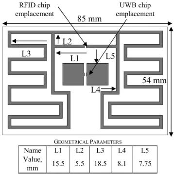
Tag is composed of two antennas, one for the UHF RFID frequency band and the other one for UWB communications (Figure 1). Constraints on RFID tag antenna an UWB antenna are obviously different. Due to the RFID chip input impedance, the antenna need to be very inductive with a few resistances [8, 9]. In order to be perfectly matched to the chip, the UHF RFID antenna's impedance should be 12+j200 Ω at 868 MHz. Folded dipole respond to those specifications [10, 11]. The impedance in UHF frequency band can be easily modified by varying L1, L2, L3 and L4 length.
UWB systems are generally matched at 50 Ω on the entire frequency band [12]. The small sizes of UWB antennas in comparison to UHF antennas permit to integrate them on a classical substrate UHF RFID substrate sizes. The shape and the way to match the UWB antenna are explained in [13].
The highest challenge is to minimize coupling effect between UHF and UWB antennas.
TABLEI GEOMETRICAL PARAMETERS Name L1 L2 L3 L4 L5 Value, mm 15.5 5.5 18.5 8.1 7.75
54 mm
RFID chip emplacement UWB chip emplacementL1
L2
L3
L4
L5
85 mm
B. Simulations and measures.
Tag Substrate is FR4 0.8 mm thick with a relative permittivity of 4.4 and tanδ = 0.02. Substrate sizes is equivalent to credit card sizes (85x54mm).
Measurement environments are described in [14]. In the measurement condition, the antenna must be symmetric. It allows to solder half of the antenna on a metal plate considered as ground plane. In those conditions, the antenna is feed by a SMA connector which permit to deduce input impedance after deembedding.
.
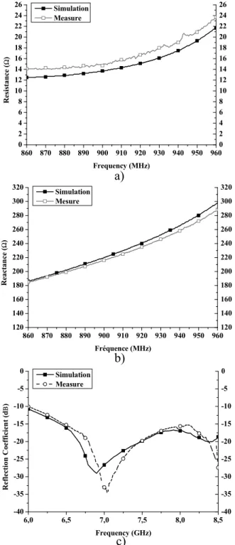
In UHF RFID band (860-960 MHz) measurements are close to simulations (Figure 2.a,b)), the main difference is a resistance greater in measurement. The impedance at 915 MHz in simulation is Z=14+j235 (Ω) with 1.5 dBi gain (Figure 2and figure 3.a)).
UWB chip has an impedance around 50Ω in European UWB's band (6-8.5 GHz) and the antenna have a reflection coefficient lower than 10dB (Figure 2.c)) with average gain around 5.5 dBi (Figure 3.c)). Coupling between antennas are principally observed in the highest frequencies as shown in figure 3.c.
Figure 2: Tag antenna a) UHF resistance b) UHF reactance c) UWB reflection coefficient
860 870 880 890 900 910 920 930 940 950 960 0 2 4 6 8 10 12 14 16 18 20 22 24 26 0 2 4 6 8 10 12 14 16 18 20 22 24 26 Resi st an ce ( Ω ) Frequency (MHz) Simulation Measure 860 870 880 890 900 910 920 930 940 950 960 120 140 160 180 200 220 240 260 280 300 320 120 140 160 180 200 220 240 260 280 300 320 R ea ct an ce ( Ω ) Fréquence (MHz) Simulation Mesure 6,0 6,5 7,0 7,5 8,0 8,5 -40 -35 -30 -25 -20 -15 -10 -5 0 -40 -35 -30 -25 -20 -15 -10 -5 0 Re fl ec ti on Coe ffi ci en t (d Β ) Frequency (GHz) Simulation Measure
a)
b)
c)
-20 -15 -10 -5 0 5 0 30 60 90 120 150 180 210 240 270 300 330 -20 -15 -10 -5 0 5 Gai n ( d B i) x,z axis y,z axis x,y axis -20 -15 -10 -5 0 5 10 0 30 60 90 120 150 180 210 240 270 300 330 -20 -15 -10 -5 0 5 10 Gai n ( d B i) x,z axis y,z axis x,y axisa)
b)
Figure 3: Gain and radiation patterns of tag antenna a) at 915 MHz b) at 7.25 GHz c) maximum gain on UWB band
c)
6,0 6,5 7,0 7,5 8,0 8,5 0 1 2 3 4 5 6 7 8 9 10 0 1 2 3 4 5 6 7 8 9 10 M axi m u m Gai n (d B i) Frequency (GHz)Tag antennas respect the specifications in term of sizes and matching. The RFID and UWB antennas are easily reconfigurable by varying the parameters previously describe. On UHF band, coupling effect between antennas are negligible, radiation pattern at 915 MHZ have the classical shape for dipole without perturbations. Coupling effects between the antennas are more important in UWB frequency band as it shows on the radiation pattern at 7.25 GHz. The antennas have common directivity along Y axis.
III. READER ANTENNA
A. Design
The reader is a single antenna matched on twice band (860-960 MHz and 6-8.5 GHz) with an impedance of 50 Ω. The substrate is epoxy 1.6mm thick with
ε
r =4.4 and tanδ=0.02.The antenna sizes are 131x18.8mm and substrate sizes are 180x60 mm (Figure 4). Its structure is composed of planar dipoles. The reasons are: it is not necessarily to have a ground (because dipoles are differential antennas) and it is possible to make wideband matching [12, 13].The main planar dipole is a straight dipole it's a narrow band antenna easily configurable on UHF RFID band. The other dipoles are bow-tie antennas mostly used for UWB applications [13]. Connections between these different dipoles are assumed by lines. These lines are as thin as possible (100 µm) in order to have impedance close to open circuit on UHF band. Thanks to that, at 915 MHz most of the current is propagate through the straight dipole. In the highest frequencies current distribution is most homogeneous on all of the dipoles. Geometrical parameters are summarized on figure 4.
B. Simulation and Measurements
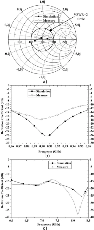
In UHF band the reflection coefficient is lower than -10 dB. In this frequency band measures are not perfectly closed to simulation (Figure 5 b)) due to a difference of reactance (Figure 5 a)). Between 6 and 8.5 GHz reflection coefficient are lower to 14 dB in simulation and 12.5 dB on measures
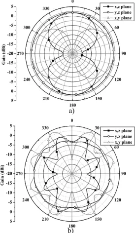
(Figure 5 c)).The radiation pattern at 915 MHz is equivalent to a classical dipole radiation pattern because most of the current is propagated through the main dipole. At 915 MHz maximum gain is 1.8 dBi (Figure 6.a)). In higher frequencies, the current distribution is homogeneous so around 7.25 GHz the antenna radiates in many directions (Figure 6.b)). The main dipole is the most fluent parameter in UHF RFID band. To enlarge or shift the UWB match band without perturb too much matching in UHF band it is advised to only vary the sizes and the angle of the bow-tie antenna [6].
0,2 0,5 1,0 2,0 5,0 -0,2j 0,2j -0,5j 0,5j -1,0j 1,0j -2,0j 2,0j -5,0j 5,0j Simulation Measure GEOMETRICAL PARAMETERS
Name L1 L2 W1 W2 Insert sep ang Value, mm 70 8 5 1 1.25 1 25 6,0 6,5 7,0 7,5 8,0 8,5 -40 -35 -30 -25 -20 -15 -10 -5 0 -40 -35 -30 -25 -20 -15 -10 -5 0 Ref lex io n Coef fi ci en t (d B) Frequency (GHz) Simulation Measure
b)
Figure 5: Reader antennas: a) impedance b) UHF RFID band and c) UWB band reflection coefficient
0,86 0,87 0,88 0,89 0,90 0,91 0,92 0,93 0,94 0,95 0,96 -30 -28 -26 -24 -22 -20 -18 -16 -14 -12 -10 -8 -6 -4 -2 0 -30 -28 -26 -24 -22 -20 -18 -16 -14 -12 -10 -8 -6 -4 -2 0 Ref lec ti on Coef fi ci en t ( d B) Frequency (GHz) Simulation Measure
a)
Figure 4: Reader antenna
180 mm
60 mm
ang
insert
sep
L2
L2
L1
W1
W2
c)
VSWR=2 circleReader antenna is the summation of two dipoles antennas. Each dipole is a classical antenna for the associate application. They are matched on twice band and have a common radiation area on UHF and UWB frequency band. Thanks to that it is possible to communicate and feed a tag on a direction. Substrate and fabrication process permit to minimize cost production.
IV. CONCLUSION
This article presented different antenna's topologies for UHF and UWB RFID applications. Concerning tag antennas, a multi-chip solution was chosen and the main difficulties consist to minimize coupling effects between UHF and UWB antenna. UHF antenna has typical impedance and it is possible to reconfigure it easily to every kind of UHF RFID chip impedance. UWB antenna has a classical shape and the reflection coefficient is lower than 10 dB. Reader antenna cover twice band with an impedance of 50Ω. It's matched in simulation and measure to all UHF RFID and European UWB bands with a reflection coefficient lower than 10 dB. Perspectives are to design a reader and tag antenna matched on all UHF RFID and FCC UWB frequency band.[13]
REFERENCE
[1] H. Sanming, L. Choi Look, and D. Wenbin, "Measurements of UWB Antennas Backscattering Characteristics for RFID Systems," in
Ultra-Wideband, 2007. ICUWB 2007. IEEE International Conference on,
2007, pp. 94-99.
[2] S. Hu, C. L. Law, and W. Dou, "Petaloid antenna for passive UWB-RFID tags," Electronics Letters, vol. 43, 2007.
[3] M. B. Nejad, C. Chen, H. Tenhunen, and L.-R. Zheng, "An Innovative Semi-UWB Passive Transponder for Wireless Sensor and RFID Applications," in Industrial and Information Systems, First
International Conference on, 2006, pp. 310-315.
[4] FCC, "First Report and Order : Revision of Part 15 of the Comission’s Rules RegardingUltra-Wideband Transmission Systems," F. C. C. 02-48, Ed., 2002.
[5] Ecc, "decision of 24 march 2006 on the harmonised conditions for devices using ultra-wideband (uwb) technology in bands below 10.6 GHz," E. C. Committee, Ed., 24 march 2006.
[6] M. D. Ben Allen, Ernest Okon , Wasim Malik , Anthony Brown , David Edwards, Ultra Wideband Antennas and Propagation for
Communications, Radar and Imaging, Wiley ed., 2006.
[7] L. M. Mohammad Ghavami, Ryuji Kohno Ultra Wideband Signals and
Systems in Communication Engineering, Wiley ed., 2004.
[8] K. V. S. Rao, P. V. Nikitin, and S. F. Lam, "Antenna design for UHF RFID tags: a review and a practical application," Antennas and
Propagation, IEEE Transactions on, vol. 53, pp. 3870-3876, 2005.
[9] T. Deleruyelle, P. Pannier, and S. Bourdel, "Multi-standard slot antenna in 860-960 MHz and 2.45GHz RFID band," in Antennas and
Propagation Society International Symposium, 2008. AP-S 2008. IEEE,
2008, pp. 1-4.
[10] C. Chi Ho and R. D. Murch, "Antenna modifications for enhancing RFID tag reading range," in Antennas and Propagation Society
International Symposium, 2007 IEEE, 2007, pp. 1084-1087.
[11] G. Marrocco, "The art of UHF RFID antenna design: impedance-matching and size-reduction techniques," Antennas and Propagation
Magazine, IEEE, vol. 50, pp. 66-79, 2008.
[12] W. Xuan Hui and C. Zhi Ning, "Comparison of planar dipoles in UWB applications," Antennas and Propagation, IEEE Transactions on, vol. 53, pp. 1973-1983, 2005.
[13] C. Zhi Ning, M. J. Ammann, Q. Xianming, W. Xuan Hui, T. S. P. See, and A. Cat, "Planar antennas," Microwave Magazine, IEEE, vol. 7, pp. 63-73, 2006.
[14] Y. Tikhov, K. Yongjin, and M. Young-Hoon, "A novel small antenna for passive RFID transponder," in Microwave Conference, 2005
European, 2005, p. 4 pp.
Figure 6: Gain patterns of reader antenna a) at 915 MHz b) at 7.25 GHz b) -20 -15 -10 -5 0 5 0 30 60 90 120 150 180 210 240 270 300 330 -20 -15 -10 -5 0 5 Ga in (d B i) x,z plane y,z plane x,y plane -20 -15 -10 -5 0 5 0 30 60 90 120 150 180 210 240 270 300 330 -20 -15 -10 -5 0 5 Ga in ( dB i) x,z plane y,z plane x,y plane a)