HAL Id: tel-02417674
https://tel.archives-ouvertes.fr/tel-02417674
Submitted on 18 Dec 2019
HAL is a multi-disciplinary open access archive for the deposit and dissemination of sci-entific research documents, whether they are pub-lished or not. The documents may come from teaching and research institutions in France or abroad, or from public or private research centers.
L’archive ouverte pluridisciplinaire HAL, est destinée au dépôt et à la diffusion de documents scientifiques de niveau recherche, publiés ou non, émanant des établissements d’enseignement et de recherche français ou étrangers, des laboratoires publics ou privés.
Chuan Zhang
To cite this version:
Chuan Zhang. Aluminum foams composite : elaboration and thermal properties for energy stor-age. Materials. Université de Technologie de Troyes, 2017. English. �NNT : 2017TROY0015�. �tel-02417674�
THESE
pour l’obtention du grade de
DOCTEUR de l’UNIVERSITE
DE TECHNOLOGIE DE TROYES
Spécialité : MATERIAUX, MECANIQUE, OPTIQUE ET NANOTECHNOLOGIE
présentée et soutenue par
Chuan ZHANG
le 7 juillet 2017
Aluminum Foams Composite:
Elaboration and Thermal Properties for Energy Storage
JURY
M. Y.-Q. GUO PROFESSEUR EMERITE Président
M. H. BADREDDINE MAITRE DE CONFERENCES Directeur de thèse M. A. EL HAMI PROFESSEUR DES UNIVERSITES Rapporteur M. J. GARDAN ENSEIGNANT CHERCHEUR EPF Examinateur M. X.-L. GONG PROFESSEUR DES UNIVERSITES Directeur de thèse M. H. HADDADI PROFESSEUR DES UNIVERSITES Rapporteur
1
Acknowledgements
Three years research experiences in France are challenging, unforgettable and meaningful, and it will be a valuable lesson for my life. During the study, all the work could not be completed without the assistance of the surrounding people in the University of Technology of Troyes (UTT). I would like to express my deepest gratitude to them and the China Scholarship Council (CSC) for the financial support. First of all, I am especially grateful to my supervisors, GONG Xiao-Lu and Houssem BADREDDINE, for their valuable guidance, constructive suggestions and constant encouragement. They not only provide a good research foundation for this thesis, but also give me many precious advices in the experiment design and result analysis. Their positive attitude for work always prompts me to move forward in both scientific research and daily life.
Thanks to the defense committee.
I am hugely appreciative to F.WEIL and B.LESAGE for their assistances in the preparation of the samples in Halle industrielle. And thanks to J.GARDAN, who provides us with the mold prepared by 3d impression in EPF. Thanks to the project Effi-SiEMCE for the technical and material support.
I am also grateful to my friends HAN.HC, WEN.ZM, ZHANG XH, ZHANG Y and other friends at UTT, who help and accompany me along these years.
I would like to thank my parents their love and wait in expectation.
2
Abstract
The objective of this thesis is to study and optimize the manufacturing process of metal foams and the thermal behavior of the aluminum foam/phase change material (PCM) composite by experimental and numerical methods. The manufacturing process of open-cell aluminum foam is developed and optimized to precisely control the parameters of manufacturing. Two pore-scale models of high porosity aluminum foams (HPAF)/PCM composite and low porosity aluminum foams (LPAF)/PCM composite are established for numerical simulation. By simulating the melting process of a layer energy storage system, the HPAF/PCM and LPAF/PCM composite are compared numerically in order to evaluate the energy storage performance. The results show that aluminum foam improves greatly the heat transfer process in PCM due to its high thermal conductivity. The porosity of aluminum foams could not only influence the melting process of composite but also the energy storage performance. Thanks to the collaboration with EPF, a new manufacturing method of periodic open-cell aluminum foams is developed based on 3D rapid tooling. The thermal behavior of the periodic open-cell aluminum foams/PCM composite is experimentally and numerically analyzed.
Keywords: Metal foams; Heat storage; Metallic composites; Thermal analysis; Simulation methods; Three-dimensional printing
3
Résumé
L'objectif de cette thèse est d'étudier et d'optimiser, par des méthodes expérimentales et numériques, le processus de fabrication des mousses métalliques et le comportement thermique des mousses composites aluminium/matériau à changement de phase (MCP). Le processus d’élaboration des mousses d’aluminium à pores ouverts est développé et optimisé pour contrôler précisément les paramètres des échantillons. Deux modèles de mousse d'aluminium à haute porosité (MAHP)/MCP composite et de mousse d'aluminium à faible porosité (MAFP)/MCP composite sont définis pour la simulation numérique. La comparaison de ces deux modèles est réalisée numériquement en simulant le processus de fusion d'un système de stockage d'énergie thermique permettant d'évaluer les performances de stockage. Les résultats obtenus montrent clairement que l’utilisation des mousses améliore le processus de transfert thermique dans le MCP. La porosité des mousses pourrait non seulement affecter le processus de fusion du MCP mais aussi influencer les performances de stockage d'énergie. La méthodologie d’élaboration des mousses d'aluminium à pores ouverts et périodiques mise en place est basée sur l’utilisation de techniques d’impression 3D. Le comportement thermique des mousses composites d'aluminium à pore périodiques ouvert et MCP est analysé expérimentalement et numériquement.
Mots clés : Mousses métalliques; Chaleur -- Stockage; Composites à matrice métallique; Analyse thermique; Simulation, Méthodes de ; Impression 3D
4
Table of contents
Acknowledgements ... 1 Abstract ... 2 Résumé ... 3 Table of contents ... 4 General introduction ... 10 Chapter 1 Bibliography ... 12 1.1 Introduction ... 141.2 Preparation methods of metal foams and structure characteristics of metal foams 15 1.2.1 Manufacturing techniques of closed-cell foams ... 15
1.2.2 Manufacturing techniques of open-cell foams... 18
1.3 Structure and Property of Metal Foams ... 23
5
1.3.2 Thermal properties and applications ... 28
1.4 Phase change material ... 31
1.4.1 Various phase change materials ... 31
1.4.2 Advantages and disadvantages of different PCMs ... 33
1.5 Modeling of metal foam... 35
1.5.1 Pore geometry models ... 36
1.5.2 The advantage of the Tetrakaidecahedron model ... 37
1.6 Technology of 3D printing ... 38
1.6.1 Main steps of 3D printing process ... 39
1.6.2 Various AM processes ... 41
1.7 Conclusion ... 43
Chapter 2 Manufacturing process of the aluminum foam ... 45
2.1 Introduction ... 47
2.2 Traditional manufacturing process of the aluminum foam ... 47
6
2.2.2 Materials and their physical properties ... 50
2.2.3 Problems in traditional manufacturing method ... 51
2.3 Improvement and upgrading of manufacturing process of the aluminum foam 52 2.3.1 Improvement and upgrading of experimental equipment ... 52
2.3.2 Foam aluminium structure control ... 54
2.3.3 Experimental results of aluminum foam manufactured under different negative pressures ... 68
2.4 Conclusion ... 71
Chapter 3 Experimental and numerical investigation of thermal performance of LPAF/PCM and HPAF/PCM composite ... 73
3.1 Introduction ... 75
3.2 Thermal performance of materials ... 75
3.2.1 Thermal property of pure paraffin ... 76
3.2.2 Thermal property of aluminum alloy ... 78
7
3.3.1 Modified Kelvin Model for High Mechanical Property Open-cell
Metal Foam ... 80
3.3.2 Simulation of the Thermal Conductivity ... 83
3.3.3 Validation of the modified Kelvin Model and Kelvin Model ... 85
3.3.4 Finite Element Model ... 86
3.4 Results and Discussions ... 87
3.4.1 Melting process ... 88
3.4.2 Comparison of Different Structural Models ... 90
3.4.3 Effect of Porosity ... 91
3.5 Conclusion ... 92
Chapter 4 Thermal behavior analysis of open-cell metal foams manufactured by rapid tooling 93 4.1 Introduction ... 95
4.2 Materials and method ... 97
4.2.1 Preparation of mold ... 97
8
4.2.3 Experimental setup and procedure ... 105
4.3 Results and Discussion ... 107
4.3.1 Effect of metal foam microstructures ... 107
4.3.2 Temperature variations of the detected points ... 109
4.3.3 Difference of Temperature ... 113
4.4 Conclusion ... 114
Chapter 5 Conclusions and perspectives ... 116
5.1 Conclusion ... 117
5.2 Perspectives... 119
Chapter 6 Résumé en français ... 121
6.1 Introduction ... 122
6.2 Elaboration des mousses d'aluminium ... 123
6.2.1 Méthode d’élaboration classique des mousses d'aluminium ... 123
6.2.2 Problèmes reliés à la méthode classique d’élaboration des mousses d’aluminium ... 125
9
6.2.3 Amélioration du processus d’élaboration des mousses d'aluminium ...
... 126
6.2.4 Résultats expérimentaux des mousses d'aluminium élaborées sous différentes pressions négatives ... 127
6.3 Modélisation et simulation numériques du comportement thermique des mousses composites ... 129
6.3.1 Méthodologie de modélisation ... 129
6.3.2 Modèle éléments finis ... 131
6.3.3 Résultats et discussions ... 132
6.4 Etude du Comportement thermique des mousses d’aluminium dont le processus de fabrication est basée sur la technique d’impression 3D ... 137
6.4.1 Elaboration du moule par impression 3D du plâtre ... 137
6.4.2 Dispositif et procédure d’étude expérimentale ... 139
6.4.3 Résultats et discussion ... 140
6.5 Conclusions ... 145
10
General introduction
Metal foams, especially aluminum foams, are widely studied thanks to their exceptional properties. They have a low density, an excellent capacity for energy absorption, heat transfer and sound absorption. Metal foams also have a large internal surface due to the porous structure. The mechanical properties of open-cell aluminum foams have been studied since over ten years in our laboratory. The open-cell aluminum foams are a promising functional material which could be widely applied in energy storage filed. This thesis focuses on the study of the enhancement effect of the aluminum foams on the heat transfer in phase change materials (PCMs).
In the first chapter, the preparation methods, structure characteristics, thermal properties of open-cell aluminum foams and 3D printing technology are introduced. Besides, the classification and characteristic of PCMs are presented, because they are the critical materials in the energy storage. The whole additive manufacturing (AM) process and several AM technologies are described.
In the second chapter, the preparation process of aluminum foams with the negative pressure infiltration method is presented. The advantages and disadvantages are analyzed. Thus the improvement and upgrading methods are proposed and achieved. After the improvement and upgrading methods, the properties of aluminum foams could be accurately controlled. The porosities of aluminum foams under different negative pressures are compared.
11
In the third chapter, a model of the high mechanical property open-cell metal foam is proposed and validated by comparing with the experimental results. The melting processes of paraffin in two models are both simulated and the results are compared and discussed.
In the chapter 4, a fabrication method of periodic open-cell metal foams is presented, combining the traditional casting method and the 3D printing by plaster and binder jetting. With the help of this method, the morphological and geometrical parameters of open-cell metal foam is designed and controlled according to the manufacturing constraints. After manufacturing the metal foam based on tetrakaidecahedron geometry, the thermal performance of energy storage system is investigated
In the chapter 5, the main conclusions of this thesis are summarized and some perspectives are provided for future studies.
12
13
Chapter 1Bibliography ... 12
1.1 Introduction ... 14
1.2 Preparation methods of metal foams and structure characteristics of metal foams 15 1.2.1 Manufacturing techniques of closed-cell foams ... 15
1.2.2 Manufacturing techniques of open-cell foams... 18
1.3 Structure and Property of Metal Foams ... 23
1.3.1 Characteristics of the structure of metallic foams ... 24
1.3.2 Thermal properties and applications ... 28
1.4 Phase change material ... 31
1.4.1 Various phase change materials ... 31
1.4.2 Advantages and disadvantages of different PCMs ... 33
1.5 Modeling of metal foam... 35
1.5.1 Pore geometry models ... 36
1.5.2 The advantage of the Tetrakaidecahedron model ... 37
1.6 Technology of 3D printing ... 38
1.6.1 Main steps of 3D printing process ... 39
1.6.2 Various AM processes ... 41
14
1.1 Introduction
Metal foams appeared in the early forties. They have advantages such as low density, thermal insulation properties, sound insulation and electrical insolation. The use of this material is very promising in the following fields: civil engineering, aeronautics, naval, automobile, medical, transport, etc. (Ashby et al., 2000)
We can separate the metal foams into two large families according to their pore types: closed-pore metal foams and open-pore metal foams as shown in Figure 1.1. It should be noted according to Figure 1.1 that the microstructure of the open pores is better arranged than that of the closed pores, but the cost of making open pores is much higher than that of closed pores during industrial production. Typical commercial products are currently: Cymat, Alulight, Alporas (brands of closed-pore metal foams); And ERG, Inco (open pore).
15
1.2 Preparation methods of metal foams and
structure characteristics of metal foams
Thanks to the development of manufacturing technology, many kinds of preparation methods of metal foams have been proposed and developed in recent decades (Wadley, 2002). In order to obtain pore structure of metal foams, there are several preparation methods for open-cell and closed-cell metal foams in this part. Depending on the manufacturing method, the structures and properties of metal foams are also different, such as porosity, pores per inch (PPI), and permeability. In this section, several common manufacturing techniques for metal foams are described.
1.2.1
Manufacturing techniques of closed-cell foams
Foaming of molten metal by gas injection
The first method of making metal foams was developed by Hydro Aluminum
Corporation in Norway and sold by Cymat Aluminum Corporation of Canada.
16
Figure 1.2 Foaming of molten metal by gas injection(Banhart, 2001)
The open-cell metal foam is produced by gas injection below the surface of a melted molten and SiC particles mixture. The bubbles thus created then rise towards the surface but do not burst. The stable foam is formed and it is necessary to obtain this foam on the surface, then it is put in the form of a slab before cooling it on a conveyor to obtain semi-finished products. The size of the cells, and also the density, is controlled by adjusting the flow rate of the injected gas.
Foaming of molten metal with foaming agent
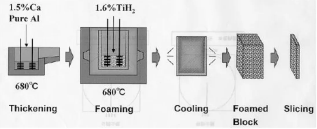
The modern method of metal foam was developed by Shinko Wire, Amagasaki in 1985, and this type of metal foam is known as the "Alporas" brand. Figure 1.3 describes this method in which calcium is added to the molten aluminum at 680 ° C, the molten metal is stirred for several minutes during which the viscosity of the molten metal increases substantially and continuously. Once the viscosity is high enough, the emulsion of titanium hydride generally is added and then decomposed, thereby emitting the hydrogen gas causing the emulsion process. The emulsion
17
process is carried out at a constant pressure. After the crucible has been cooled below the melting point of the aluminum alloy, the liquid foam solidifies and could thus be removed from the mold for subsequent machining.
Figure 1.3 Foaming of molten metal with foaming agent(Banhart, 2001)
Powder metallurgy
The method of powder metallurgy for the production of metal foams is carried out by TIFAM (the Fraunhofer Institute for Applied Materials Research) (Ashby et al., 2000; Banhart, 2001) and by the Bratislava University in collaboration with the Karmann company. The foams produced by this technique are known as the trade mark "Alulight". Figure 1.4 describes the principle of the powder metallurgy method. The metal powders and an emulsifying agent (often titanium dichloride) are mixed and then this mixture is consolidated by pressure, the semi-finished product assembly takes the form of the cold mold under compression. The foaming process is controlled by heating the semi-finished product assembly above 550 ° C (for aluminum binder), decomposing the foaming agent at high
18
temperature. This technique allows produce the production of the mold-shaped metal foam.
Figure 1.4 The sequence of powder metallurgy steps used to manufacture metal foams by gas-releasing particles in semi-solids (the Fraunhofer and the Alulight processes) (Ashby et al., 2000)
1.2.2 Manufacturing techniques of open-cell foams
Infiltration flow with polymeric foam
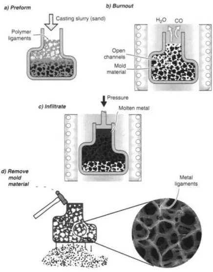
Figure 1.5 presents the method of making open-cell foams under the trademark "Duocel". In this technique, the polymeric foam of the open cell structure is placed in a mold and then filled with different materials such as mud, sand or plaster.
19
Figure 1.5 Investment casting method used to manufacturing open cell foams (DUOCEL process) (Ashby et al., 2000)
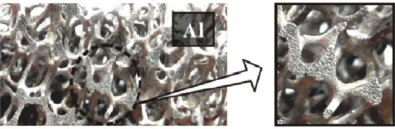
After filling, the blown polymer foam of the mold volatilizes and the molten metal is filtered in place of the polymeric foam by gravity or suction pressure and heating of the mold. Finally, after the demolding, metal foams are obtained and take up the initial structure of the polymeric foam, as shown in Figure 1.6 (Ashby et al., 2000; Yamada et al., 2000).
20
Figure 1.6 metal foam produced by investment casting method(Yang et al., 2016b)
Depot of metal by vapor in the cellular preform
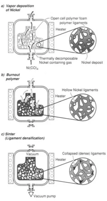
Open-cell nickel foams are manufactured by the technique of metal vapor deposition. The metal foams produced take the trade mark "Inco". In this technique, the polymeric foam of the open cell structure is placed in a mold and then the vapor of composition of the nickel (Ni(CO)4) decomposes. The nickel
metal is deposited on the surface of the polymeric foam, and the polymeric foam is then burned. After the sintering, open-cell nickel foams could be obtained. This technique is described in Figure 1.7.
21
22
Figure 1.8 Metal foam produced by electro-deposition method (Yang et al., 2016b)
Infiltration flow with filler
Figure 1.9 describes this technique for the preparation of open-cell metal foams. The molten metal is filtered in a heated preform, and this preform is often inorganic particles, sand or salt (San Marchi and Mortensen, 2001), organic (such as polymer) or even hollow spheres. Firstly, the preform of the salt particles is sintered to improve its quality. The molten metal will be filtered under a specific pressure. The cooling of the mixture is subsequently dissolved by washing with water, and the aluminum foams are thus obtained(San Marchi and Mortensen, 2001).
23
Figure 1.9 Schematic of the replication process for the production of metallic foam Among all manufacturing techniques above, it could be concluded that the infiltration technique with filler is the most easily controllable. At the same time, other advantages such as the low cost of equipment and the simple implementation are also reasons why we chose this technique for our study, which is described in detail in Chapter 2 and the ameliorated method based on this method in Chapter 4.
24
1.3.1 Characteristics of the structure of metallic foams
The metal foam can be considered a composite composed of two elements: a metal and air. To describe the structure of metallic foams, two characteristics are important: the relative density and the porous structure. In most of the research articles published in this field, the mechanical properties of metal foam are mainly represented by two characteristics: properties of solid metal and relative density of metal foam (Ashby et al., 2000). In recent years, more and more researches are concentrating on the porous structure of metal foams.
The relative density is the most important characteristic of metal foams. It is one of the macroscopic characteristics, defined by the density of the metal and the percentage of metal and air. For some typical metal foams, their relative density is less than 0.35. Sometimes the structure of real foams is very complex, so the determination of the density is relatively difficult due to its inhomogeneity. Moreover, the exact measurement of the actual structure is virtually impossible. However, it could be obtained by the Archimedes' principle. It is difficult to find a specimen that has a closed complement surface in order to obtain the total volume.
The porous structure is other important characteristic of metal foams. A pore can be composed of knots, edges and walls (in closed-cell metal foams). The mechanical behavior of metal foams depends on local stresses within metal foams, where flexion, wrinkling, plastic creep and local fracture occur. Moreover, the density of the foam is also inhomogeneous because of the inhomogeneity of the porous structure, and this leads to a change of mechanical behavior of the metal
25
foams. Because of this complicity of pores, the following parameters are often used to describe it:
The pore: volume fraction, pore size, orientation and measured diameter
(maximum, minimum and average diameter, and shape).
The arrangement of the pore: the pore arrangement rule, the number of adjacent
pores, the length, the thickness and the flexion of the edge, the distance of the adjacent pores.
The structure of the pore: the number of nodes, the number of edges and walls in
each pore, the angle of the edge, the shape of the edge, the number of walls that connects to an edge, Length and thickness of the wall, the number of walls that connects to a knot, the curvature and the fold on a wall ... etc.
Most metal foams have defects which unfortunately affect their mechanical and thermal properties. Typical defects include bending of the edge, crushing (bending) on the wall and on the edge etc. The macroscopic modulus of elasticity is thus decreased. In addition, other factors may also influence the mechanical and thermal properties of metal foams, such as:
Micro-cracks
Existing lumpy surfaces on the wall
The shrinkage cavities
26
Figure 1.10 Micro-cracks of spheres' shells (a)specimen Cu5 and (b) specimen Cu20(Narayana)
Figure 1.10 shows the micro-cracks in the metal foams, from this figure, it could be observed that the width of these micro-cracks is not great, but the length is very long, which forms a long gap. The formation of these micro-cracks is associated with many factors, such as the casting process, cooling process and demolding process.
27
Figure 1.11 cavities in the sample of aluminum foam
Figure 1.11 shows the cavities in the sample of metal foam. These cavities are large in size, about 10-20mm. They greatly affected the quality of the sample.
These micro-cracks, cavities and other defects will have a significant impact on the properties of metal foams. Therefore, we should try to reduce the defects in the metal foam in order to obtain metal foams with great mechanical and thermal properties.
These parameters could not explain precisely the influence of structures on mechanical properties. Recently, some new researches in the literature (Brezny and Green, 1990; Chen and Lakes, 1995; Grenestedt and Bassinet, 2000) have presented the relationships between metal foam structures and their mechanical
28
and thermal properties but so far this field of research is far from complete and remains many important points to study.
1.3.2 Thermal properties and applications
Due to the deepening of the research, the mechanical properties of metal foam are no longer the only focus, the thermal properties and the acoustic properties of metal foams were studied. In the field of thermodynamics, that open-cell metal foams are promising materials for heat exchangers (Boomsma et al., 2003; Mellouli et al., 2009) because of their high internal surface areas and porous structures, which may contribute to the heat transfer process. Compared with traditional metal fins, metal foams have larger specific surface area and higher mechanical strength. This section describes the thermal properties of metal foams and their applications in the field thermodynamics.
Thermal properties
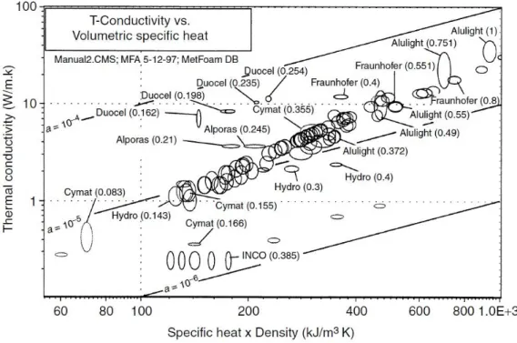
Thermal properties include the following thermal parameters: melting temperature, specific heat, coefficient of expansion, thermal conductivity, thermal diffusivity and thermal radiation ... etc.(Boomsma et al., 2003; Zhao and Wu, 2011). Thermal conductivity is the determining property of heat response in steady state; the thermal diffusivity determines the transient behavior. Figure 1.12 shows that aluminum foams have low thermal conductivities and that thermal diffusivities are relatively high. All aluminum foams with closed cells have almost the same value of thermal diffusivity α.
29
Figure 1.12 Thermal conduction according to the specific heat for different metal foams (Ashby et al., 2000)
Applications
The thermal conductivity of metal foams is higher than that of non-metal foams, for closed-cell metal foams, their thermal conductivity is lower than that of solid metal, so they could be use as fire protection materials. For open-cells metal foams, they can be used to improve heat transfer in applications such as heat exchangers for embedded equipment, compact heat sinks for electronic equipment, heat shields, air-cooled condenser towers and the regenerators (Antohe et al., 1996; Kaviany, 1985). We also have some remarks such as:
30
(2) In open-cell metal foams, the interconnected cells have a large specific area. This characteristic makes it possible to be used as catalyst support, heat exchanger and energy absorber of mechanical shock.
Figure 1.13 Heat exchanger element based on metal foam
Figure 1.13 shows a heat exchanger based on metal foam, the metal foams could enhance the performance of the heat exchanger thanks to their high specific surface area.
31
1.4 Phase change material
In recent years, with development the economic and social, the energy becomes the main focus of researches in every country. We should not only study new energy, but also study the energy storage and reuse in order to reach the purpose of saving energy. The phase change material becomes the promising material in the field of energy storage due to its thermal performance.
1.4.1 Various phase change materials
There are three main methods to store energy, sensible heat, latent heat and chemical energy. They are all used in different field according to their different thermal properties. Figure 1.14 shows the classification of energy storage material. In this figure, there are two types of PCM, the organics and the inorganics.
32
Table 1-1 shows the comparison of thermal and physical properties between sensible heat storage materials (rock and water) and latent heat storage materials (organic and inorganic). By comparing the relative storage mass and the relative storage volume, the advantage of the latent heat storage materials is very clear. The latent heat storage materials could store same amount of energy with lighter weight and less volume.
Table 1-1 Comparison between the different methods of heat storage (Hasnain, 1998)
Property
Rock
Water
Organic
PCM
Inorganic
PCM
Density, kg/m
32240
1000
800
1600
Specific heat, kJ/kg
1.0
4.2
2.0
2.0
Latent heat, kJ/kg
–
–
190
230
Latent heat, kJ/m
3–
–
152
368
Storage mass for
10
6J, kg
67,000 16,000
5300
4350
Storage volume for
10
6J, m
330
16
6.6
2.7
Relative storage mass
15
4
1.25
1.0
Relative storage
volume
11
6
2.5
1.0
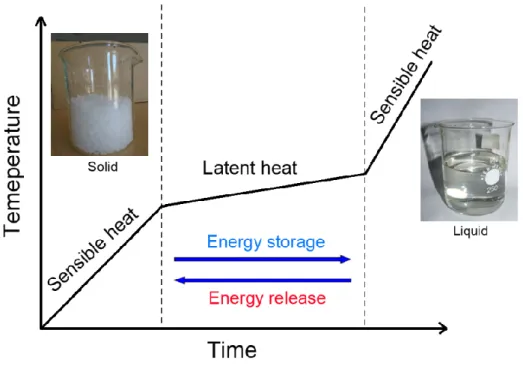
Figure 1.15 shows the basic principle process of energy storage in PCMs. When the temperature increases, the energy stored in PCMs is mainly the sensible heat. When the melting point is reached, the solid-liquid phase transition occurs in PCMs. In this step, the temperature increases much more slowly and the energy stored is mainly the latent heat. After PCMs are totally melted, the sensible heat becomes again the main form of energy storage. This energy storage process is repeatable and reversible. The PCMs always have a large value of latent heat,
33
which makes the PCMs could absorb or release a large amount of energy with a small temperature variation during the phase change process. Therefore, PCM could store large amounts of energy during the phase change process with small temperature variation, which brings great convenience to a variety of applications.
Figure 1.15 Principle process of energy storage and release of PCMs
1.4.2 Advantages and disadvantages of different PCMs
There are two main types of PCMs, the organic PCMs and the inorganic PCMs. The representative organic PCMs are paraffin, polyethylene glycol and fatty acid. For inorganic PCMs, the representative materials are Na2SO4·10H2O,
Na2HPO4·12H2O and Na(CH3COO)·3 H2O. The advantages of organic PCMs are
34
However, they have also disadvantages, low latent heat, low thermal conductivity and inflammability. For inorganic PCMs, they have a larger latent heat than organic PCMs. But they have great disadvantages, undercooling, corrosion and phase separation, which largely limit their applications in the field of energy storage. The thermal stability of PCMs is very important, because the application environment is very complex.
There are some important properties of PCMs are necessary if they are used in the field of energy storage. They are described as following (Abhat, 1983): (1) the latent heat of PCMs should be as great as possible, and the temperature of phase change should be fitted to the application condition; (2) the variation of the volume before and after the phase change should be small; (3) their chemical properties should be stability, safety, nonflammable; (4) the phase separation should be avoided. According to these limits, it is seen that both types of PCM are not perfect, thus we should chose the suitable PCMs according to different application conditions.
Table 1-2 Advantages and disadvantages of the organic/inorganic PCMs Type Representation
materials Advantages Disadvantages
Organic PCMs Paraffin Polyethylene glycol Fatty acid No corrosive; Low undercooling; Chemical and thermal stability
Low latent heat; Low thermal conductivity; Inflammability Inorganic PCMs Na2SO4·10H2O Na2HPO4·12H2O Na(CH3COO) ·3 H2O
Large latent heat
Undercooling; Corrosion; Phase separation;
35
1.5 Modeling of metal foam
The metal foam structures are inhomogeneous, their geometric profiles are very complex and the thermal and mechanical behavior shows a strong nonlinearity. It is important to model and simulate metal foams to predict their properties and give useful information in the production and application of this material. In recent years, much research has focused on the modeling and numerical simulation of metallic foams (Gibson and Ashby, 1999; Weaire et al., 1995; Weaire and Drenckhan, 2008).
Numerical modeling studies could be classified by scale of dimensions: microscopic, mesoscopic and macroscopic. The scale of the microscopic dimensions is represented by the size of the pore. We consider a single pore (or some pores) which is composed by walls, edges and nodes in order to obtain the structural relation with thermal and mechanical behavior. The property of the materials is thus obtained by the statistical method. The mathematical general equations are established on a pore and the experimental results allow us to validate these theoretical equations.
The mesoscopic scale is the scale between "micro" and "macro". The inhomogeneity of metal foams and the change in the pore are the points often studied by researchers.
The scale of the macroscopic dimensions is one hundred or one thousand times more than the size of a pore, for example the modeling on a whole specimen. Supposing the pores are homogeneous and continuous, mechanical behavior such
36
as elastic limit, plasticity, damage and rupture, are also widely studied in the literature (Deshpande and Fleck, 2000; Liu, 2007a).
The numerical simulation studies of metal foams could also be classified by their research aims: for the design of a structure using metal foams; for the elements of the metal foams are used in a complex structure. Manufacturers are more interested in manufacturing technology, the microscopic structure and the behavior of the use of foam. For these reasons, they prefer microscopic and mesoscopic modeling in order to better fit their needs and their demands.
Metal foams are an excellent functional material because they have a special microscopic structure. It is used in many fields such as radiators, filters and catalyst supports. Therefore, the modeling and simulation of heat transfer and fluid property are important. In recent years, some publications have presented the modeling of the process of foaming, in particular the fabrication by melted metallurgical method (Ma et al., 1999; Nieh et al., 1998).
1.5.1 Pore geometry models
The 2D is often applied for materials with the regular cell structure, such as hexagon cell. The 3D geometric modeling is used for porous materials of random shape. In the case, the pores are assumed to be ideal. Researchers have often used the models: spherical model (Andersen et al., 2000; Lim et al., 2002), cubic model (Lu et al., 1998), dodecahedral model (Bhattacharya et al., 2002) or tetrakaidecahedron model (Kelvin) as shown in Figure 1.16.
37
Figure 1.16 (a) spherical models; (b) cubic models; (c) dodecahedral models(d) tetrakaidecahedron (Kelvin) model
1.5.2 The advantage of the Tetrakaidecahedron model
The advantage of the tetrakaidecahedron model (Figure 1.17) is that it has an amount of faces and edges as much as the actual pore structure, and therefore closer to reality. It is widely used in numerical 3D foam modeling. The development of a tetrakaidecahedron model structure was done by Weaire and Phelan in 1994(Weaire and Phelan, 1994). They discovered a periodic unit of cells:
38
Voronoi (Figure 1.18). This Voronoi periodic unit contains: six polyhedras of 14 faces (including 12 pentagons + 2 hexagons) and two polyhedras of 12 pentagonal faces. They indicated that this model has the minimum of surface energy and closer to the real structure of metal foam pores.
Figure 1.17 Tetrakaidecahedron model cell
Figure 1.18 Periodic unit of eight tetrakaidecahedron cells
39
3D printing technology, also known as additive manufacturing or laminate manufacturing (Additive Manufacturing, AM), could refer any printing process of three-dimensional objects (Excell and Nathan, 2010). 3D printing is mainly a continuous process by adding material under computer control (Gibson et al., 2010). 3D printed objects could have any shape and geometric according different applications. 3D printers are a kind of industrial robots.
1.6.1 Main steps of 3D printing process
There are several steps in the 3D printing process (AM) in order to transfer a virtual CAD description to a real objet. This process is a complex and sophisticated process. The complexity of the whole process varies depending on the material, dimension, accuracy requirements and so on. The main steps of 3D printing process are shown in Figure 1.19.
Step 1: CAD
All AM objects should start from the geometric model. The professional CAD software is needed in order to output a 3D solid or surface model. A reverse engineering software ( laser or optical scanning) could also be used in this step.
Step 2: STL file
Almost AM machines could accept the file format of STL, which becomes a standard in the field of AM. Nearly every professional CAD software could output a STL file, so this step becomes very simple.
40 Step 3: File transfer
The STL files must be transferred to the AM machines. This step involves the correct dimension, position and orientation of the models.
Step 4: AM machine setup
Several parameters need to be set correctly, such as the material constraints, energy source, layer thickness and timings.
Step 5: Build
The building of the parts is automate and controlled by the AM machine. We should observe the process to ensure no errors during the building.
Step 6: Removal
The objects should be removed after the step 5 from the AM machines. In this step, we should follow the rules of the AM machines.
Step 7: Post-processing
The extra material should be removed from the parts. For some materials and some special structures, the surface treatment, the cutting off, special cleaning and other operations are also needed.
41
Once the 3D printed productions are obtained, the quality check is required before the application. According different application conditions, the temperature, the humidity and other environment conditions should be suitable for the parts.
Figure 1.19 Main steps of 3D printing process(Gibson et al., 2014)
1.6.2 Various AM processes
In the early researches, AM process was used to produce plastic prototypes, and several AM processes (i.e., SLA, SLS, FDM) have been developed to make different parts with various plastics. After many developments and explorations, AM technology becomes more and more mature and common. The materials are no longer just plastics, the metals, ceramics, composites and other materials could
42
be also used in AM process. Table 2 lists the types of materials that can be processed by AM technology and the corresponding processes. The various AM technologies are widely investigated, such as Stereolithography (SLA) (Jacobs, 1992), Fused Deposition Modeling (FDM)(Comb et al., 1994), Selective Laser Sintering (SLS) (Beaman et al., 1997), Laminated Objective Manufacturing (LOM) (Mueller and Kochan, 1999), Three Dimensional Printing(3DP) (Sachs et al., 1993) and Laser Metal Deposition (LMD) (Mazumder et al., 1999).
Two representative technologies, the stereolithography and selective laser sintering technology, are presented as follow.
Stereolithography (SLA)
SLA is one of the most widely used AM technologies. This AM technology is usually used for liquid
epoxy
resin based photopolymer. Figure 1.20 shows the whole SLA process.43 Selective Laser Sintering (SLS)
Selective Laser Sintering is an effective technology for durable and functional black or natural-colored parts. However, the surfaces are not enough smooth and the edges are not enough sharp. A laser beam is used to selectively fuse powder material into solid. Many materials could be used by this technology, such as nylon, thermal plastic elastomers and metals. Figure 1.21 shows the selective laser sintering (SLS) process.
Figure 1.21 Selective Laser Sintering (SLS)
1.7 Conclusion
Metal foams are very interesting materials for energy storage applications. The bibliographical studies make it possible to highlight the research already carried out on the manufacturing methods, the microscopic structures of metal foams, the
44
mechanical and thermal properties and the AM technology, etc. After many years of manufacturing development, several manufacturing methods are already mature, which offers necessary experience for the improvement and upgrading. The numerical modeling of the porous structure makes the numerical simulations possible. Therefore, the comparison of porosities and structures could be achieved. The AM technology offers a possibility to obtain periodic aluminum foams with a designed structure.
45
Chapter 2
Manufacturing
process of the aluminum
foam
46
Chapter 2 Manufacturing process of the aluminum foam ... 45
2.1 Introduction ... 47
2.2 Traditional manufacturing process of the aluminum foam ... 47
2.2.1 Equipment of manufacturing ... 49
2.2.2 Materials and their physical properties ... 50
2.2.3 Problems in traditional manufacturing method ... 51
2.3 Improvement and upgrading of manufacturing process of the aluminum foam 52
2.3.1 Improvement and upgrading of experimental equipment ... 52
2.3.2 Foam aluminium structure control ... 54
2.3.3 Experimental results of aluminum foam manufactured under different negative pressures ... 68
47
2.1 Introduction
In the second chapter, the preparation process of aluminum foams with the negative pressure infiltration method is presented. The advantages and disadvantages are analyzed. Thus the improvement and upgrading methods are proposed and achieved. After the improvement and upgrading, the properties of aluminum foams could be accurately controlled. The porosities of aluminum foams under different negative pressures are compared.
2.2 Traditional manufacturing process of the
aluminum foam
The method used to prepare the aluminum foam in our research is called ‘Infiltration casting method’ or ‘Negative pressure casting process’(Niu et al., 2000). This method is a traditional manufacturing method of open-cell metal foam based on gravity casting process(Rabiei and O’Neill, 2005; Vendra and Rabiei, 2007). It is often used to prepare the foam of Al, Mg, Zn, etc. Many advantages are offered by this method such as low cost, controllable pore size, simple process and great sample size. There are three principal steps in this method:
-Preparation of mold: a kind of soluble particles should be used as preform to
prepare a mold. We chose salt particles as the soluble particles because of its low price, high melting point and controllable particle size. Certain size salt particles are filled in a steel tube to obtain this mold. The final procedure in this step is to heat the mold to keep the fluidity of the molten aluminum during the next step.
48
-Infiltration: the molten aluminum is poured into the mold in order to fill the
spaces between the salt particles. Due to the surface tension, the gravity is not enough to make the molten aluminum fill the entire mold; a negative pressure must be applied under the mold as soon as the molten aluminum is poured into the mold(Niu et al., 2000). The pressure difference between the upper and lower surface allows the molten aluminum to fill the entire mold. This step is shown in Figure 2.1.
- Solidification: after the step of infiltration, the mixture of aluminum and salt is
immersed in water during several hours until the salt particles are all dissolved. The sample of aluminum foam is finally obtained after the water remained in the sample evaporates. Then the sample can be cut into different dimensions for various experiments.
Figure 2.1 Schematic presentation of negative pressure casting process (1- Molten Aluminum, 2-Preform(salt particles), 3-Stainless steel mold, 4- Stainless steel cup, 5-
49
2.2.1 Equipment of manufacturing
In the infiltration casting method, the foam structure of aluminum foam is based on the preform. The shape and size of the pores in aluminum foam are the copy of the particles. In order to control the shape and size of the cells in the aluminum foam, the soluble particles are grouped according to their diameters by a vibrating sieve. This vibrating sieving machine AS 200 basic Retsch® is composed of seven sieves of different sizes. It is therefore possible to separate the particles into seven different sizes according to the following diameters: 1.9, 1.6, 1.25, 1.0, 0.8, 0.58 and 0.365 mm.
After sieving, the particles of the same size are filled into a cylindrical stainless steel mold and slightly compacted to ensure a correct porosity. And then it is necessary to preheat the preform in order to avoid the solidification of aluminum at the beginning of infiltration. This process is realized by a chamber furnace, Labotherm N61/H of NaberthermThe temperature rise during preheating must be relatively slow in order to prevent the particles from cracking or rupturing by the temperature. When a predefined temperature value is reached (620 ° C), it must be maintained for at least one hour to ensure homogeneity within the preform.
The aluminum alloy is melted using a furnace, Nabertherm Labotherm K4 / 10. This furnace is characterized by its rapid temperature rise, by its bidirectional heating and its simplicity of using. Moreover, the rapid temperature rise could reduce the potential oxidation of the aluminum and thus preserves the quality of the aluminum.
50
Once the aluminum alloy is melted, the mold is placed over a suction stainless steel support. Then the liquid aluminum flows into the mold under the effect of negative pressure. This negative pressure is produced by a vacuum pump, controlled by a valve.
Due to the high corrosion of the salt, the mold is made of stainless steel, and its melting point (about 1500 ° C) is much higher than that of aluminum (about 615° C).
2.2.2 Materials and their physical properties
The choice of particles takes into account the following factors: the particles must be soluble in water, economical, and a higher melting point than that of aluminum alloy. In addition, this material should not have compatibility problem with aluminum such as chemical reaction, and these particles should not be too expensive. In this research, the salt particles were chosen as a preform whose properties are shown in Table 2-1.
Table 2-1 Properties of salt particles
(25℃) [103kg/m3] (600℃) [103kg/m3] Température de fusion [°C] Conductivité thermique (600 ℃) [W/(m°C))] Chaleur spécifique (600 ℃) [J/(kg°C)] Coef. d’expansion thermique (-50 à 200 °C) [106K-1 ] 2,165 2,158 801 4,6 1030 44
51
For aluminum foams, the main characteristic depends on the porous structure. In principle, there is no particular requirement for the chosen metal. Therefore, it was the mechanical properties of the metal and the cost price that guided our choice of material. In this study, the aluminum alloy AS7G was selected as the base metal. Physical and mechanical properties of AS7G are summarized in Table 2-2.
Table 2-2 Physical and mechanical properties of aluminum alloy AS7G
solide (103kg/m3) liquide (103kg/m3) Coef. de la dilatation α (10-6 /°C) Chaleur spécifique [J/(kg)·°C)] Température de solidification (°C) Température de fusion (°C) 2,68 2,38 21,5 879 555 615 Contrainte d’élasticité (MPa) Déformation à la rupture (%) Module D’Yong (GPa) Contrainte à la rupture (MPa)(traction) Coef. de Poisson Coef. d’expansion thermique (106K-1 ) (20 à 100 °C) 165 2 70 140 0,33 23
2.2.3 Problems in traditional manufacturing method
During the fabrication of aluminum foam with traditional method, we found several problems, such as the seal of equipment, stability of negative pressure, the adjustability of negative pressure and so on. These problems are caused by many reasons.
-Seal of equipment: after many years of use, many air leakage points appear in the iron pipe joints. Since salt is used to make foam aluminum, salt corrosion reduces the seal of the system.
52
-Stability of negative pressure: the volume of pipe is not big enough to provide a stable negative pressure. At the beginning of the application of negative pressure, the negative pressure value is the preset value, but the negative pressure value continues to weaken with the negative pressure in the tube is released.
- Adjustability of negative pressure: because of the two above problems, the adjustability of negative pressure cannot be accurate enough during the infiltration. The negative pressure can only reach –0.8atm.
All the above problems need to be resolved in order to achieve a better performance of the system.
2.3 Improvement and upgrading of
manufacturing process of the aluminum foam
2.3.1 Improvement and upgrading of experimental
equipment
According to the experimental requirements and the above mentioned problems, we have several solutions to choose. The best solution is the improvement and upgrading base on the existed equipment.
The optimized equipment is shown in Figure 2.2. Compared to the old equipment, a grand vacuum tank, a manometer and a extra valve are added in the optimized equipment. These improvements are described below.
53
- Vacuum tank: a vacuum tank is connected to the vacuum pump and the mold in order to store negative pressure. The volume of the vacuum tank is about forty times more than the volume of the mold. A sufficiently large volume allows the negative pressure to maintain a steady state during pressure release.
- Manometer: In order to obtain an accurate pressure output value, we need to monitor the pressure in the tank. A manometer is added to the vacuum tank, its range is from 0 to -0.1Mpa. Its measurement accuracy is 0.002 MPa.
Figure 2.2 Schematic presentation of optimized equipment (1- Molten Aluminum, 2-Preform(salt particles), 3-Stainless steel mold, 4- Stainless steel cup, 5- Valve, 6-
Vacuum pump, 7 - Manometer, 8- Vacuum tank )
-Valve: the second valve is added to the experimental equipment to control the opening and closure between the vacuum pump and the vacuum tank. This valve is opened when the vacuum pump is working, and it is closed when the negetive pressure reaches the preset value.
54
Beside the additions of vaccum tank, manometer and valve, other upgrades are also achieved: all the joints of pipe are sealed with silicone, and a seal verification was done. When the mold is placed on the platform,
2.3.2 Foam aluminium structure control
With this manufacturing method, the arrangement irregularity of the particles results from the stacking technique, therefore it is difficult to define the arrangement of the pores. Since the shape of the particles and the stacking technique are invariant in our study, the influence of the shape and the stacking of the particles on their mechanical and thermal behaviors can be considered as invariable and therefore they are not taken into account in our consideration. Thus the adjustable parameters of the elaboration are the pore size and the porosity of aluminum foam.
During the preparation, the following parameters directly influence the quality of the foams: temperature, pressing time, preheating, geometry and preparation of the mold, negative pressure etc.
1. Control of the pore size
During the casting process, the molten aluminum is filled into the space which is left by the salt particles. Therefore the shape and size of the cells duplicate those of the particles. After the solidification process, the aluminum contracts so that the volume and diameter of the cells increase. Then, once the soluble particles are dissolved in water, the pores form and take the form of the particles. Thus, in order
55
to simplify the approach, the diameter of the pores will be considered as equal to that of the particles.
2. Control of the porosity
According the process of manufacturing, the volume of pore could be divided into three parts.
1) The biggest part is the volume of the particles, called ‘volume of preform Vp’.
2) The second part is called ‘additional volume Va’, it is formed due to the surface
tension of the liquid aluminum.
3) The third volume is called ‘volume of shrinkage Vs’, it is formed due to the
shrinkage of aluminum during the solidification.
In the end, we obtain the volume of pores by the following relation, as shown in Figure 2.3.
𝑉 = 𝑉𝑝+ 𝑉𝑎 + 𝑉𝑠 (2-1)
The porosity Ppore is directly deduced from this volume:
𝑃𝑝𝑜𝑟𝑒 = (𝑉𝑝 + 𝑉𝑎 + 𝑉𝑠)/𝑉𝑇𝑜𝑡𝑎𝑙 (2-2)
56
Figure 2.3 Description of the different volumes
The mechanical and thermal behavior of aluminum foam depends largely to its porosity. It can be controlled by adjusting the stack of the particles in the mold and by changing the negative pressure etc. According to other researches about the stack of the salt particles (He, 2004; Liu, 2007b; Wang, 2010), it is known that the arrangement of salt particles could largely influents the porosity of aluminum foam, such as the time of vibration of salt particles.
Due to the improvement and upgrading of manufacturing process of the aluminum foam, we focus on the influence of negative pressure to the porosity of aluminum foam.
In order to study and analyze the effect of negative pressure to the porosity of aluminum foam, the infiltration process must be firstly studied. The infiltration process of molten aluminum through the stacked salt particles is a complex process because it involves multi-phase flow (including air and liquid) in porous media. In addition, the infiltration process may also be affected by several factors:
57
preform size, temperature, pressure and surface tension. Until now, the infiltration process with common conditions could be well explained (Masur et al., 1989; Mortensen et al., 1989; Mortensen and Wong, 1990). These research works are mainly based on the capillary law and Darcy's law, which are two useful and important theories of the infiltration process. The detail discussions of these two laws are following.
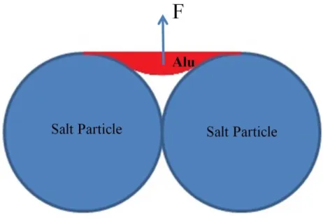
Capillary law
During the infiltration process, the liquid aluminum is non-wetting for the salt particles, so there will be a force F (shown in Figure 2.4) this force is caused by the surface tension. This force F prevents the liquid aluminum from filling into the void space by gravity, as shown in Figure 2.4.
Figure 2.4 Schematic of the non-wetting phenomenon between liquid aluminum and salt particles
58
Therefore, in order to overcome the surface tension of liquid aluminum, a minimum pressure which is called the threshold pressure (P0) should be obtained.
This threshold pressure P0 is determined by Garcia et al. (Garcia-Cordovilla et al.,
1999). If the preform particles are approximated as spheres, the threshold pressure is shown as follows:
0 6 cos 1 p p V P D V ( 2-3)Where, γ is the surface tension of liquid aluminum; θ is called the contact angel at liquid and solid interface; Vp is the particle volume; D is the average diameter of
salt particles.
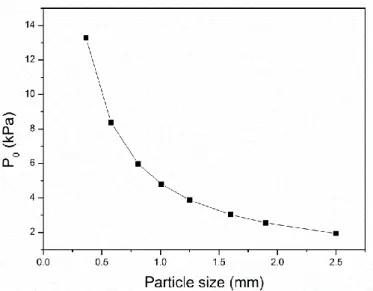
Before the infiltration process, the threshold pressure should be estimated firstly, and the negative pressure which is applied during the infiltration process should be larger than this threshold pressure. For our experiment, we found that the value of
Vp has no relationship to the particle size, and this value is always about 0.52
without vibration and compaction. If Vp is always a constant value, the threshold pressure is the function of pore size. The value of surface tension γ and value of contact angel could be found in other researches, they are 0.85 N m-1 (Goicoechea et al., 1992) and 152° (Berchem et al., 2002), respectively. The results of P0 are
shown in Figure 2.5(Zhu, 2017). It is observed that the threshold pressure reduces as the increase of the salt particle size. Thus, for the small particle, a large negative pressure should be applied to make the liquid aluminum penetrate into the void of salt particles.
59
Figure 2.5 Threshold pressure (P0) as the function of the salt particle size Darcy's Law
In order to describe the relationship between pressure drop and velocity during the infiltration process in the porous media, the Darcy’s law is always used. But the classical form of Darcy´s law, as shown in equation (2-4), should be deduced in the condition that the porous zone is full filled by liquid.
(
)
K
dP
u
dx
(2-4)Where, u is the velocity; μ is the viscosity; P is the pressure; K is the permeability. In fact, the infiltration process could be seen as the process that the liquid aluminum takes the position of air in the porous zone. The movement of two-phase flow in the preform is essential for the infiltration process. Because of the non-wetting phenomenon and the surface tension of liquid, the void space could not be filled totally by liquid. In order to study and analyze the infiltration process
60
of the non-saturated flow, the relative permeability is presented in the Darcy´s law(Molina et al., 2005) and the new equation is obtained, it is called Extended Darcy’s law, shown in equation (2-5).
(2-5)
where, Ks is the permeability of a specific preform and it is also a physical
property of material; Kr is the relative permeability. The relative permeability is a
value between 0 and 1, and it depends on the saturation of two flows. The relationship between relative permeability and saturation could be expressed by equation (2-6).
B r
K = As
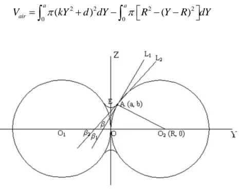
(2-6)where, A and B are constants and s is the value of saturation which is equal to the ratio of the liquid volume to the void space of preform. The infiltration process of metal-matrix composite was studied by T. Dopler et.al (Dopler et al., 2000) and they found that the numerical results have the best agreement with experimental ones when the values of A and B equal to 1. In addition, for the saturation, S.Y, HE (He, 2004) considered the surface tension of the liquid aluminum will prevent the liquid from filling all the void space. He established a model which could be used to calculate the volume of air, as presented in Figure 2.6 Geometry model of the air position between two particles. Finally, he found that the air fraction depends on two values, the particle size (ds) and negative pressure (P).
61 2 2 2 2 0
(
)
0(
)
a a airV
kY
d dY
R
Y
R
dY
(2-7)Figure 2.6 Geometry model of the air position between two particles
On the basis of other researches and theories above, we found more phenomena from our experiments, such as the effect of turbulent flow, the capillary phenomenon on the lower surface, non-uniform pressure distribution etc. These effects and phenomena will be discussed as follow.
Effects of turbulent flow
First of all, the Reynolds number (Re) needs to be determined in order to define the
flow of liquid aluminum is turbulent flow regimes or not. The equation of Reynolds number is defined as:
62
Where, ρ is the density of the fluid, v is a characteristic velocity of the fluid with respect to the object, D is a characteristic linear dimension and μ is the dynamic viscosity of the fluid. However, for the Reynolds number of flow in porous media should be expressed as:
𝑅
𝑒𝑝=
ρvdμ (2-9)Where, the d replaces the D in equation (2-8), it is the average dimension of voids among the salt particles in this research.
In order to define the velocity of the flow (v), the permeability should be calculated according to the equation:
2 3
150(1
)
pd
K
(2-10)Where, dp is the average diameter of particle and ε is the porosity of packed bed. It
is found that this correlation could be applied in the low porosity metal foam. Since the permeability K is obtained, the velocity (v) could be calculated according to equation (2-5).
It is well known that the flows of high-velocity in porous zones generate turbulence in the pores when the pore-Reynolds (Rep) number is greater than 300
(Alvarez et al., 2003), which is much smaller than the limit value of Re=2000.
Two main differences between flow in porous zones and turbulent of free-stream flow are the dimension of eddies is limited by the size of pores and the additional
63
force effects which are caused by viscous and form of the porous solid matrix. In our research, the Rep of our aluminum foam sample is about 2000 which is much
greater than the limit value, 300. So it could be confirmed that the flow of liquid aluminum through porous media is turbulent flow.
The infiltration process is a very fast process, the velocity of flow could reach 0.82m/s and the pore-Reynolds reaches 2000, so there must be swirls and holes in the process of infiltration. Marcos H et al. (Marcos H. J. Pedras, 2001) simulated the flow in porous media and obtained the vector plots for different porosities, as shown in Figure 2.7(Marcos H. J. Pedras, 2001). From this simulation, it is obviously that a number of swirls are produced in porous media, and the air will be left into the liquid aluminum due to these swirls. It can be seen that these swirls are bigger if the porous size is smaller. The porous size of our samples is much smaller than that of the Figure 2.7(c) (the porous size of our samples is 2mm and the porous size of Figure 2.7(c) is 30mm), the arrangement is more compact and the shape of pores is more complicated. Therefore, the swirls in liquid aluminum during the infiltration process are more complicated and countless.
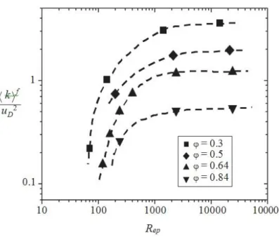
According to equation (2-5) and (2-9), when the pressure applied is greater, the velocity of flow is greater and the pores-Reynolds number is increased. If the pores-Reynolds number is increased, the turbulent kinetic energy is also increased, as shown in Figure 2.8 (Kuwahara et al., 2006). Finally, it can be concluded that the turbulent kinetic energy increases with the increase of negative pressure.
64
Figure 2.7 Vector plots, (a) ε=0.4; (b) ε=0.6; (c) ε=0.8
These strong swirls will keep more air in liquid aluminum, and the most of air remains under the salt particles, that is to say, a greater negative pressure will keep more air in the behind of the salt particles.
65
Figure 2.8 Macroscopic turbulent kinetic energy
Effects of non-uniform pressure distribution
Due to the complex structure of salt particles preform, the pressure during the infiltration process is not uniform. Marcos H et al. (Marcos H. J. Pedras, 2001) simulated also the pressure distribution of the flow in porous media for different porosities, as shown in Figure 2.9. From the contours of pressure distribution, it is obvious that the pressure in small voids is much higher than the left and right sides of salt particles, and the pressure of left side is higher than the right side, it means that the side facing to the liquid flow bears a greater pressure than the other side. Therefore, the liquid aluminum in the small voids is affected by several forces, such as gravity, surface tension and the force caused by high-speed liquid flow. The force analysis diagram of liquid aluminum in small voids is shown in Figure 2.10. This diagram is modified based on Figure 2.4, the gravity and the forces of flow are considered. For the molten aluminum on the top, F1 isthe surface tension
66
and F2 is the resultant force of all downward forces (gravity and force of flow),
because of the volume of liquid aluminum entering the voids becomes larger, which is shown by dashed lines in Figure 2.10. For the molten aluminum on the bottom, F3 is the force of flow and F4 is the resultant force of all downward forces
(gravity and surface tension). F3 is much smaller than F2 and F4 is much greater
than F1, so the upper liquid volume is much greater than the lower volume.