HAL Id: tel-01685016
https://tel.archives-ouvertes.fr/tel-01685016
Submitted on 16 Jan 2018HAL is a multi-disciplinary open access archive for the deposit and dissemination of sci-entific research documents, whether they are pub-lished or not. The documents may come from teaching and research institutions in France or abroad, or from public or private research centers.
L’archive ouverte pluridisciplinaire HAL, est destinée au dépôt et à la diffusion de documents scientifiques de niveau recherche, publiés ou non, émanant des établissements d’enseignement et de recherche français ou étrangers, des laboratoires publics ou privés.
Surface modification of cellulose nanocrystals by
esterification and ATRP reactions for advanced
applications
Zhen Zhang
To cite this version:
Zhen Zhang. Surface modification of cellulose nanocrystals by esterification and ATRP reactions for advanced applications. Polymers. Université de Bordeaux, 2017. English. �NNT : 2017BORD0653�. �tel-01685016�
THÈSE PRÉSENTÉE POUR OBTENIR LE GRADE DE
DOCTEUR DE
L’UNIVERSITÉ DE BORDEAUX
ÉCOLE DOCTORALE
SCIENCES CHIMIQUES
Spécialité : Polymères
Par Zhen ZHANG
MODIFICATION DE LA SURFACE DES NANOCRISTAUX DE
CELLULOSE PAR ESTERIFICATION ET POLYMERISATION
ATRP POUR DES APPLICATIONS AVANCEES
Sous la direction de : Gilles SEBE et Xiaosong WANG
Soutenue le 5 septembre 2017
Membres du jury :M. TAM Michael Professeur, Université de Waterloo Président M. GILLIES Elizabeth Professeur, Université de Western Ontario Rapporteur M. NAVARD Patrick Directeur de recherche, MNES ParisTech Rapporteur M. CRAMAIL Henri Professeur, Université de Bordeaux Examinateur M. LEONARDI Frédéric Maître de Conférences, Université de Pau Examinateur M. ADRONOV Alex Professeur, Université de McMaster Examinateur M. WANG Xiaosong Professeur associé, Université de Waterloo Examinateur M. SEBE Gilles Maître de Conférences, Université de Bordeaux Examinateur
ii
iii
AUTHOR'S DECLARATION
I hereby declare that I am the sole author of this thesis. This is a true copy of the thesis, including any required final revisions, as accepted by my examiners.
iv
Abstract
Cellulose nanocrystals (CNC) are bio-based nanoparticles, which display an array of interesting properties related to their renewability, biocompatibility, high tensile strength and elastic modulus, high aspect ratio, low density, low coefficient of thermal expansion, and liquid crystal behavior. As a result, CNC can be exploited in a wide variety of applications, which include the fields of composites, catalysts, emulsions or colloidosomes. However, the engineering of innovative nanomaterials from CNC generally requires a fine control of their surface properties by chemical modification, to tailor their dispersive, interfacial and self-assembling properties, or to introduce novel functionalities. In this context, the surface functionalization of cellulose nanocrystals by esterification and Surface-Initiated Atom Transfer Radical Polymerization (SI-ATRP) reactions was envisaged, with the objective to develop novel advanced materials.
The first chapter describes the state-of-the-art of the field in which the cellulose nanocrystals are presented, with their properties, methods of functionalization and potential applications. A brief overview of the SI-ATRP reaction is also given.
In the second chapter, a convenient method is proposed to directly characterize the polymer grafted by SI-ATRP on the CNC surface, without cleaving the polymer from the nanoparticle. The SI-ATRP grafting of polystyrene (PS) at the CNC surface was performed from brominated CNC initiators, in the presence of a sacrificial initiator. With this work, we show that Dynamic light scattering (DLS) is a convenient tool to monitor the polymerization process, while differential scanning calorimetry (DSC) can be used to verify if the polymerization rates of the grafted and free polymers coincide. Finally, we demonstrate that thermogravimetric analysis (TGA) can be used to directly estimate the molecular weight of the PS grafted at the surface of the CNC without cleaving the polymer from the nanoparticle. In the third chapter, both SI-ATRP and Surface-Initiated Activator Re-Generated by Electron Transfer ATRP (SI-ARGET ATRP) were conducted to graft PS and P4VP on the surface of CNC. The SI-ATRP and SI-ARGET ATRP approaches were systematically compared to evaluate the potential benefit of each method. The surface initiating efficiencies (SIE) of the CNC-Br macroinitiators with regards to styrene or P4VP were evaluated by TGA and EA, respectively. The combination of analytical methods
v
such as FT-IR, DLS, DSC, TGA, and EA demonstrated that the SI-ARGET ATRP reaction favored the grafting of longer polymer chains with lower grafting densities compared with the classical SI-ATRP method. The impact of catalyst concentration and propagation rate on the differences noted was particularly discussed.
In the fourth chapter, pH-responsive P4VP-g-CNC nanohybrids were prepared by SI-ATRP and subsequently used to stabilize gold nanoparticles (Au NPs) and produce recyclable catalysts. The presence of P4VP brushes at the CNC surface led to the growing of Au NPs of lower averaged diameter compared with the diameter of the Au NPs deposited on pristine CNC. The catalytic performance of pristine Au NPs, Au NPs stabilized by CNC (Au@CNC) and Au NPs stabilized by P4VP-g-CNC (Au@P4VP-g-CNC) were then compared, through the measurement of the turnover frequency (TOF) obtained after catalytic reduction of 4-nitrophenol (4NP), used as a model reaction. Compared with pristine Au NPs, the catalytic activity of Au@CNC and Au@P4VP-g-CNC were about 10 and 24 times better, respectively. Moreover, the Au@P4VP-g-CNC material could be conveniently recovered by flocculation at basic pH, and the recycled catalyst remained highly active.
In the fifth chapter, Ultraviolet (UV)-responsive poly(cinnamoyloxy ethyl methacrylate) (PCEM) was grafted on CNC using SI-ATRP. The resultant PCEM-grafted CNC (PCEM-g-CNC) exhibits high UV absorption properties and undergoes crosslinking under UV irradiation. When the PCEM-g-CNC nanohybrids were incorporated in poly(vinyl chloride), transparent composite films with UV-blocking properties were obtained. The comparison of the optical and mechanical properties of the films before and after UV-irradiation allowed it to be demonstrated that the PCEM-g-CNC nanoparticles also acted as thermal and UV-stabilizers for PVC. Meanwhile, the tensile mechanical properties of the PVC film were significantly improved, and further increased after UV-irradiation.
In the sixth chapter, a facile method to prepare colloidosomes at room temperature is proposed from w/o inverse Pickering emulsions containing silica precursors and stabilized by cinnamate modified CNC (Cin-CNC). Cin-CNC Pickering surfactants were prepared by acylation with an excess of cinnamoyl chloride. The Cin-CNC surface displayed partial wettability with both toluene and water, which allowed stabilization w/o inverse Pickering emulsions. The Cin-CNC particles around the droplets were subsequently locked by cross-linking TEOS or TBOS silica precursors at the
vi
water/toluene interface, leading to an intricate network of polysiloxane within the Cin-CNC shell. In optimized conditions, the Cin-CNC/silica colloidosomes obtained displayed a robust shell and slow releasing capacity with regards to encapsulated molecules such as rhodamine B or fluorescent deoxyribonucleic acid (DNA).
In the last chapter, we summarized the general conclusions of the thesis and proposed some recommendations for the future work. The cellulose nanocrystals were modified by esterification and surface initiated Atom Transfer Radical Polymerization. The characterization, mechanism and advanced applications of the functionalized CNC were envisaged. Based on the research and results in this project, we also proposed some recommendations for the future work on the modification of CNC and the other advanced applications.
vii
Acknowledgements
I would like to thank my supervisors, Dr. Gilles Sèbe and Dr. Xiaosong Wang, for the Ph.D. opportunity and guidance in the past several years. I completed the initial one and half years at Bordeaux, France. Dr. Sèbe introduced me to the amazing world of CNC. I am impressed by Dr. Sèbe’s interests about scientific research and his prudent scientific attitude. Dr. Sèbe always tells me “play with your CNC materials.” The interests in the CNC keep me full of energy in the process of exploring. Dr. Sèbe reviewed the slides for the first presentation of the group meeting from word to word. From that moment on, I knew every word on the slides matters. I completed the second part of my Ph.D. program at Waterloo, Canada. The most important thing I learned from Dr. Wang is how to write and revise a draft. I learned a lot from every revision. Moreover, Dr. Wang always tells me the importance of communication and presentation. The presentation is worth revising several times to be better and better as an audience will spend 20 min or longer listening to your presentation.
I am very thankful to all the committee members of Ph.D. defense: Dr. Elizabeth Gillies, Dr. Patrick Navard, Dr. Michael Tam, Dr. Henri Cramail, Dr. Frédéric Léonardi, Dr. Jean Duhamel and Dr. Alex Adronov. Thanks for your help and inspiring discussion. I also would like to thank my Ph.D. committee members: Dr. Michael Tam, Dr. Eric Prouzet, and Dr. John Honek. They gave me many suggestions during the comprehensive exam and the committee meeting. Some ideas of this thesis are inspired by their helpful suggestions. Thanks a lot for the suggestions and help. I also learned a lot from Dr. Tam’s attitude to life and his leadership, from which I will benefit through my whole life.
I would like to express my gratitude to University of Waterloo, Bordeaux University, and International Doctoral School in Functional Materials (IDS-FunMat) for all kinds of support.
I am very thankful for my talented labmates, Jérémie Brand, Benjamin Dhuiege, Shaowei Shi, Kai Cao, Dapeng Liu, Nimer Murshid, Nicholas Lanigan, Heyan Jiang, Na Zhou, Diya Geng, Liao Peng, Maria Cheng, Mia San Gabriel, Zengqian Shi, Zhaolin Yao, Juntao Tang, Jianxiang Chen, Nathan Grishkewich, Nishil Mohammed, Li Chen, Xinyao Zhou, Debbie Wu, Fatima Awan, Jiyoo, Parinaz, Maria, Zhenle Cao, Stephen Wei, Yibo Liu, Takayuki Sakajiri, Haoquan Liu, Marjan Ashrafi, Salha Alharthi, and so on. These amazing lab mates always motivated and encouraged.
viii
I also would like to thank all the technician and administrative staff at Bordeaux and Waterloo, such as Cathy, Caroline, Paul, Mishi, Christopher, Audrey, Marianne, Catherine, etc.
I would like to express my gratitude to my friends at Bordeaux and Waterloo, Xuan Wang, Xiaobo Hu, Yan Cai, Haohao Duan, Shusheng Zhang, Kai Huang, Ruie Liu, Jie Yao, Yijun Yuan, Bosi Mao, Yana Zhou, Yingying Yang, Xuesong Li, Wei Chen, Qin Liang, Jinhong Zhang, Qiaodan Fang, Xiang Wang, Hao Pan, Weisheng Liu, Monoj, Tianjiao Cai, Jingwen Diao, Yunjie Xia, Jinkai Yuan, Jian Zhi, Yinghui He, Danny Wang, Luzhu Xu, Zhuo Chen, Yu Pei, Dorothy, Sandeep, Prakash, Sasha, Jinhua Wang, Xin Ma, Hairui Liu, Xin Cong, Jiang Xu, Bin Yang, Rui He, Wei Chen, Xue Cao, Baoshi Sun, Liu Wang, Qiang Zhang, Mi, Dongzhi Zhang, Zijie, Ziming Zhu, Junshan Li, Eids, Sergey, Edgar, Peng Chen, Yuki, . All of you make my life different. I would also like to thank my friends in China, Yuping Qiao, Chengtao Wang, Shiyun Sun, Xu Zhang, Linfei Dong, Yuting Yang, and Antonio. Without their help and support, I would not have finished my Ph.D. I would also like to thank my mentors, Yihua Zhu, Xiaoling Yang, Dong Zheng and Chenan Dai.
I also would like to thank all the people who helped me and all the people who said hi to me in the last four years. At the beginning, I replied “good” when the cleaner of the QNC said “how are you doing today?” He told me “why not great, wonderful? Every day is a special day. You should live in the present.” Thanks for the inspiring and encouraging hi.
When I resigned my career as a supply chain manager from P&G in August of 2013, I was 26 years old. I started the PhD program in May of 2014, which is almost 9 months later after my resignation. It is totally 4 years for me to pursue the Doctor degree from August of 2013 to September of 2017. I am 30 years old now. That was the best ages of my life. I am not sure how many 4-years do I still have. In the last 4 years, I have been happy, hopeful, confused, frustrated and lost. In the last 4 years, I experienced some of my happiest time of my life, and also experienced the worst time of my life. It is a little naïve to say “I never regret”. Sometimes I may regret what I have said and done. But if I had a chance to live my life again, I would make the exactly same choice. In the last 4 years, I have met some wonderful person and also some other people. Some are real friends and worthy treasuring for a lifetime. Everything happens for some reason and purpose. I am grateful for what I have experienced
ix
before and what I possess now. From now on, I am not young anymore, but I will never be old. Therefore, I will try my best to cherish and enjoy every single day of my life.
Last but not the least, I would like to thank my family, Ruiguang Zhang, Shiying Bin, Yan Zhang, Niu Zhang, Jinshu Lu, Yinuo Li, Jianuo Li and the unborn baby. Your unconditional love and support keep me going. You are the reason and the purpose. I love you!
x
Dedication
xi
Table of Contents
AUTHOR'S DECLARATION ... iii
Abstract ... iv
Acknowledgements ... vii
Dedication ... x
Table of Contents ... xi
List of Figures ... xvii
List of Tables ... xxvi
Chapter 1 State-of-the-art ... 1
1.1 Cellulose nanocrystals (CNC) ... 1
1.1.1 Introduction to CNC ... 1
1.1.2 The chemical modification of CNC... 7
1.1.3 The application of CNC ... 17
1.2 Atom transfer radical polymerization (ATRP) ... 26
1.2.1 Living free radical polymerization ... 26
1.2.2 The mechanism of ATRP ... 30
1.2.3 Development of ATRP ... 31
xii
Chapter 2 Convenient Method for the Characterization of Polymers Grafted by SI-ATRP on Cellulose
Nanocrystals, Using DLS, DSC and TGA ... 38
2.1 Introduction ... 39
2.2 Experimental ... 40
2.2.1 Materials ... 40
2.2.2 Preparation of the brominated CNC nano-initiator: CNC-Br ... 41
2.2.3 Grafting PS from CNC-Br by SI-ATRP: PS-g-CNC ... 41
2.2.4 Characterization ... 42
2.3 Results and discussion ... 43
2.3.1 Preparation and characterization of the CNC-Br initiator ... 43
2.3.2 SI-ATRP grafting of PS from CNC-Br ... 47
2.4 Conclusions ... 55
Chapter 3 A comparative study on the Surface grafting of Polystyrene and Poly(4-vinylpyridine) on Cellulose Nanocrystals by SI-ATRP and SI-ARGET ATRP ... 56
3.1 Introduction ... 57
3.2 Experimental ... 59
3.2.1 Materials ... 59
xiii
3.2.3 Grafting PS from CNC-Br using SI-ATRP: PS1-g-CNC ... 59
3.2.4 Grafting PS from CNC-Br using SI-ARGET ATRP: PS2-g-CNC ... 60
3.2.5 Grafting P4VP from CNC-Br using SI-ATRP: P4VP1-g-CNC ... 61
3.2.6 Grafting P4VP from CNC-Br using SI-ARGET ATRP: P4VP2-g-CNC ... 61
3.2.7 Characterization ... 61
3.3 Results and discussion ... 62
3.3.1 Preparation of the CNC-Br initiator ... 62
3.3.2 SI-ATRP and SI-ARGET ATRP grafting of PS on CNC ... 63
3.3.3 SI-ATRP and SI-ARGET ATRP grafting of P4VP on CNC ... 68
3.3.4 Proposed mechanism to account for the different SIE found with SI-ATRP and SI-ARGET ATRP ... 71
3.4 Conclusions ... 72
Chapter 4 Recyclable Gold Nanoparticles Stabilized by Poly(4-vinylpyridine) Grafted Cellulose Nanocrystals for the Efficient Catalysis of 4-Nitrophenol Reduction ... 74
4.1 Introduction ... 75
4.2 Experimental ... 76
4.2.1 Material and instrumentation ... 76
xiv
4.2.3 Preparation of P4VP-g-CNC by SI-ATRP ... 77
4.2.4 Preparation of the catalysts dispersions: pristine Au NPs, Au@CNC, and Au@P4VP-g-CNC ... 78
4.2.5 Evaluation of the catalytic performance of pristine Au NPs, Au@CNC, and Au@P4VP-g-CNC ... 78
4.3 Results and discussion ... 79
4.3.1 Preparation and characterization of P4VP-g-CNC... 79
4.3.2 The preparation and characterization of the Au@ P4VP-g-CNC catalyst ... 82
4.3.3 Catalytic performance and recyclability of Au@ P4VP-g-CNC ... 85
4.4 Conclusions ... 89
Chapter 5 Enhanced Thermal Stability and UV Resistance of Poly(vinyl chloride) Reinforced by UV-absorbing Poly(Cinnamoyloxy Ethyl Methacrylate) Grafted Cellulose Nanocrystals ... 91
5.1 Introduction ... 92
5.2 Experimental ... 94
5.2.1 Materials ... 94
5.2.2 Synthesis of monomer: cinnamoyloxy ethyl methacrylate (CEM) ... 94
5.2.3 Preparation of the brominated CNC nano-initiator: CNC-Br ... 95
xv
5.2.5 Preparation of the PVC films ... 95
5.2.6 UV irradiation experiments ... 96
5.2.7 Characterization ... 96
5.3 Results and discussion ... 97
5.3.1 Preparation and characterizations of the PCEM-g-CNC nanohybrids ... 97
5.3.2 Impact of UV irradiation on PCEM-g-CNC ... 101
5.3.3 Preparation and properties of composite PVC films filled with PCEM-g-CNC nanohybrids ... 105
5.4 Conclusion ... 111
Chapter 6 Inverse Pickering Emulsions Stabilized by Cinnamate Modified Cellulose Nanocrystals (Cin-CNC) as Templates to Prepare Cin-CNC/Silica Colloidosomes ... 112
6.1 Introduction ... 113
6.2 Experimental ... 115
6.2.1 Materials ... 115
6.2.2 Preparation of the Cin-CNC Pickering emulsifiers ... 115
6.2.3 Preparation of the inverse Pickering emulsions stabilized by Cin-CNC ... 115
6.2.4 Preparation of the Cin-CNC/silica colloidosomes ... 115
xvi
6.3 Results and discussions ... 117
6.3.1 Preparation and characterization of the Cin-CNC Pickering emulsifier ... 117
6.3.2 Preparation and properties of the inverse Pickering emulsions stabilized by Cin-CNC ... 122
6.3.3 Preparation and characterization of Cin-CNC/Silica colloidosomes ... 125
6.4 Conclusions ... 131
Chapter 7 General Conclusions... 132
xvii
List of Figures
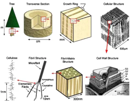
Figure 1.1.The structure of wood: from tree to cellulose8 ... 2
Figure 1.2. The intramolecular (A) and intermolecular (B) hydrogen bonding in the structure of cellulose9 ... 2
Figure 1.3. Crystal and amorphous regions in the cellulose found in plant and isolation of CNC by sulfuric acid hydrolysis of the amorphous regions. ... 3
Figure 1.4. (A) Optical image of CNC aqueous dispersion (10 mg/ml); (B) the fingerprint patterns of CNC film when observed by polarized optical microscopy; (C) optical image of flow-induced birefringence for 1.5 mg/mL CNC aqueous suspension observed between cross-polarizers;20 (D)
schematic representation of the chiral nematic self-assembly of CNC, along with an illustration of the half-helical pitch P/2 (~ 150-650 nm).21 ... 6
Figure 1.5. Surface chemistry of the CNC extracted by different methods6 ... 8
Figure 1.6. The surface modification of CNC by adsorption.7 ... 8
Figure 1.7. Common modification methods used for the surface modification of CNC by small molecules.6 ... 9
Figure 1.8. The Surface functionalization of CNC by transesterification of vinyl esters.20,28 ... 10
xviii
Figure 1.10. Main strategies used to graft polymers on nanoparticles: “grafting to” or “grafting from”
approaches. ... 12
Figure 1.11. Common modification methods used for the surface modification of CNC by polymer grafting (blue arrows = “grafting to”; yellow arrows = “grafting from”). 47 ... 13
Figure 1.12. The preparation of PS-g-CNC by SI-ATRP57 ... 14
Figure 1.13.The preparation of CNC-Br with high Br content by the two steps method.55 ... 15
Figure 1.14. The preparation of PtBA-g-CNC and PAA-g-CNC by SI-ATRP.55 ... 16
Figure 1.15.The preparation of PDMAEMA-g-CNC by SI-ATRP.58 ... 16
Figure 1.16.The tensile strength (a) and modulus (b) of the PVA film reinforced with increasing amounts of PABA; and schematic representation of the UV filtering and reinforcing effect of PABA-CNC (c). 70 ... 18
Figure 1.17. The schematic illustration of the preparation of Au NPs@CNC for the reduction of 4-nitrophenol (4NP).82 ... 19
Figure 1.18 The schematic representations of the O/W classical emulsion and O/W Pickering emulsion85 ... 21
xix
Figure 1.20. SEM images of polymerized styrene droplets stabilized by different types of CNC.13 a, d
and g: CNC with small aspect ratio extracted from cotton; b, e, and h: bacterial cellulose; c, f and i:
CNC with high aspect ratio extracted from Cladophora ... 23
Figure 1.21. The SEM images of typical colloidosomes.97 ... 24
Figure 1.22. Different routes to prepare colloidosomes microcapsules98 ... 25
Figure 1.23. (A) Degree of polymerization vs. monomer conversion for step-growth polymerization, chain-growth polymerization, and living polymerization; (B) The monomer conversion and ln [M0/Mt] as a function of reaction time in living polymerization ... 27
Figure 1.24. The different steps of free radical polymerization, with the reaction rate of each step108 ... 28
Figure 1.25. Reversible balance to transfer active species to dormant species ... 29
Figure 1.26. The mechanism of ATRP 42 ... 30
Figure 1.27. The ln [M0/Mt] as a function of reaction time in ATRP42 ... 31
Figure 1.28. The mechanism of reverse ATRP43,117 ... 32
Figure 1.29. The mechanism of SR & NI ATRP118 ... 33
Figure 1.30. The mechanism of AGET ATRP119 ... 33
Figure 1.31. The mechanism of ARGET ATRP ... 34
xx
Figure 1.33. Schematic of proposed mechanism for eATRP43 ... 35
Figure 1.34. The surface initiated ATRP on the surface of particles or flat127 ... 36
Figure 2.1. FTIR spectra of pristine CNC, CNC-Br, PS-g-CNC after 2 h reaction, and free PS. ... 44
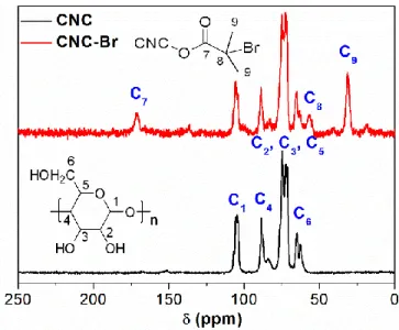
Figure 2.2. 13C CP-MAS NMR spectra of pristine CNC and CNC-Br. ... 45
Figure 2.3. TEM images showing the morphology of pristine CNC (A) and CNC-Br (B). ... 45
Figure 2.4. TGA thermograms (A) and DTG curves (B) of pristine CNC and CNC-Br. ... 46
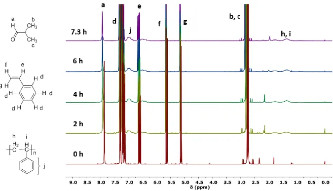
Figure 2.5 1H NMR spectra of the aliquots in CDCl 3 with different polymerization time ... 47
Figure 2.6. Kinetics of the ATRP polymerization of free PS: (A) Monomer conversion and ln([M0]/[Mt]) vs. reaction time; (B) Mn and dispersity of free PS vs. monomer conversion. ... 48
Figure 2.7. Evolution of the hydrodynamic radius (Rh) of PS-g-CNC as a function of Mnfree PS. ... 49
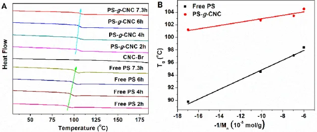
Figure 2.8. (A) DSC curves of CNC-Br, free PS, and PS-g-CNC at different polymerization time; (B) Tg of free PS and PS-g-CNC as a function of -1/Mnfree PS. ... 51
Figure 2.9. TGA thermograms (A) and DTG curves (B) of free PS ... 51
Figure 2.10. TGA thermograms (A) and DTG curves (B) of PS-g-CNC... 52
Figure 2.11. Evolution of the weight ratio of grafted PS relative to CNC-Br in PS-g-CNC (calculated by TGA) as a function of monomer conversion. ... 53
Figure 2.12. The Mngrafted PS derived by TGA and the Mnfree PS measured by GPC ... 54
xxi
Figure 3.2. (A) Hydrodynamic diameter distribution by intensity of CNC-Br, PS1-g-CNC and PS2-g-CNC; (B) DSC curves of free PS, PS1-g-CNC, and PS2-g-CNC. ... 66
Figure 3.3. TGA thermograms (A) and DTG curves (B) of CNC-Br, PS1-g-CNC, and PS2-g-CNC. ... 67
Figure 3.4. FTIR spectra of CNC-Br, P4VP1-g-CNC, and P4VP2-g-CNC. ... 69
Figure 3.5. DSC curves of P4VP, P4VP1-g-CNC, and P4VP2-g-CNC. ... 70
Figure 3.6. TGA thermograms (A) and DTG curves (B) of CNC-Br, P4VP1-g-CNC, P4VP2-g-CNC and free P4VP. ... 70
Figure 3.7. Proposed mechanism to account for the different SIE found with SI-ATRP and SI-ARGET ATRP. ... 72
Figure 4.1. FTIR spectra of CNC, CNC-Br, and P4VP-g-CNC. ... 80
Figure 4.2. (A) Hydrodynamic diameter (Dh) distribution by intensity of the CNC () and P4VP-g-CNC () dispersed in water (pH = 2); (B) Evolution of the average Dh () and Zeta-potential () of the P4VP-g-CNC suspension as a function of pH. ... 81
Figure 4.3. The TEM images of CNC (A), CNC-Br (B), P4VP-g-CNC (C) ... 81
Figure 4.4. UV-Vis absorbance spectra of the reaction medium during the preparation of Au NPs (A), Au@CNC (B) and Au@P4VP-g-CNC (C and D). ... 82
xxii
Figure 4.5. Photographs of the reaction medium during the preparation steps of the Au NPs, Au@CNC and Au@P4VP-g-CNC catalysts. Photographs were taken before (A), 1 min after (B) and 2 hours after (C) the addition of NaBH4. ... 83
Figure 4.6. The TEM images of Au@CNC (A) and Au@P4VP-g-CNC (B) ... 84
Figure 4.7. Size distribution of Au NPs in Au@CNC and Au@P4VP-g-CNC. ... 85
Figure 4.8. Time-dependent UV-vis absorption spectra of the reaction medium during the 4NP reduction catalyzed by (A) pristine Au NPs, (B) Au@CNC, and (C) Au@P4VP-g-CNC and evolution of ln(At/A0) with time (D). ... 86
Figure 4.9. (A) Schematic illustrating of the recovery of Au@CNC and Au@P4VP-g-CNC; Time-dependent UV-vis absorption spectra of 4NP reduced by NaBH4 catalyzed by recycled Au@CNC (B) and
recycled Au@P4VP-g-CNC (C); (D) shows the plots of ln(At/A0) against time for the reduction of 4NP
with different catalysts. ... 88
Figure 5.1. FTIR spectra of CNC, CNC-Br, PCEM-g-CNC and PCEM. ... 99
Figure 5.2. Images of the water droplets deposited on the glass support, before and after spin-coating with CNC and PCEM-g-CNC. ... 99
Figure 5.3. TGA thermograms (A) and DTG curves (B) of pristine CNC, CNC-Br, PCEM and PCEM-g-CNC. ... 100
xxiii
Figure 5.5. Evolution of the UV absorption of the conjugated C=C bond in PCEM (A) and PCEM-g-CNC (C) films irradiated at 365 nm for several hours; and evolution upon irradiation of the maximum absorbance () and reciprocal (▲) at 276 nm, for both PCEM (B) and PCEM-g-CNC (D) films. ... 103
Figure 5.6. FTIR spectra of PCEM and PCEM-g-CNC samples, before and after irradiation at 365 nm of their solution/dispersion (overnight irradiation accompanied by an evaporation of the solvent). ... 104
Figure 5.7. DSC curves of the PCEM and PCEM-g-CNC samples, before and after irradiation at 365 nm of their solution/dispersion (overnight irradiation accompanied by an evaporation of the solvent). ... 105
Figure 5.8. PVC, PVC/CNC (5 wt. %) and PVC/PCEM-g-CNC (5 wt. %) composite films obtained by solution casting of the corresponding DMF solutions/suspensions followed by heat annealing. ... 106
Figure 5.9. Transmittance of the PVC, PVC/CNC and PVC/PCEM-g-CNC films, before and after heat annealing at 80 oC. ... 107
Figure 5.10. Schematic representation depicting the UV-filtering and reinforcing effect of the PCEM-g-CNC filler in PVC, before and after heat annealing. The transmittances given were measured at 320 nm (UV) and 555 nm (Visible). ... 107
Figure 5.11. Transmittance of the PVC, PVC/CNC and PVC/PCEM-g-CNC films before and after UV irradiation. ... 109
Figure 5.12. Tensile stress-strain curves obtained after analysis of the PVC, PVC/CNC and PVC/PCEM-g-CNC films before and after the UV irradiation. ... 110
xxiv
Figure 6.1. FTIR spectra of pristine CNC and Cin-CNC. ... 118
Figure 6.2. TEM images of pristine CNC and Cin-CNC. ... 119
Figure 6.3. TGA thermograms (A) and DTG curves (B) of pristine CNC and Cin-CNC. ... 120
Figure 6.4. Optical images of CNC and Cin-CNC dispersions in solvents of different polarity (the dielectric constants of water, DMF, and THF are 78.54, 38.25, and 7.52, respectively). ... 120
Figure 6.5. Size distribution by intensity of the CNC and Cin-CNC particles dispersed in water, DMF or THF (0.2 mg/ml) ... 121
Figure 6.6. Images of the water droplets deposited on the glass support, before and after spin-coating with the CNC and Cin-CNC material. ... 121
Figure 6.7. Optical micrographs of the inverse water/toluene emulsion droplets stabilized with different concentrations of Cin-CNC (A, 0.25 mg/mL; B, 0.5 mg/mL; C, 1 mg/mL; D, 2 mg/mL; E, 2 mg/mL; and F, 4 mg/mL); and fluorescent micrograph of the water droplets stained by rhodamine B (E). The length of scale bar in the micrographs is 50 µm. ... 122
Figure 6.8. Size distribution of the emulsion droplets obtained at different concentrations of Cin-CNC(A); and number-average diameter D(1,0) as a function of Cin-CNC concentration. ... 123
Figure 6.9. Evolution of 1/D(3,2) as a function of Cin-CNC concentration. ... 124
Figure 6.10. Evolution of surface tension of the Cin-CNC toluene suspension and interfacial tension between toluene and water as a function of Cin-CNC concentration. ... 125
xxv
Figure 6.11. Evolution with time of the number-average diameter D(1,0) of the emulsion droplets in the Pickering systems containing TEOS or TBOS precursors (pH = 1 or 7; [Cin-CNC] = 2 or 5 mg/mL). ... 126
Figure 6.12. Evolution of the inverse water/toluene emulsion droplets with increasing amounts of ethanol: A, 0 µL; B, 20 µL; C, 40 µL; and D, 100 µL (initial volume = 200 µL; pH = 7; ([Cin-CNC] = 2 mg/mL) The length of scale bar in the optical micrographs is 50 µm. ... 128
Figure 6.13. Optical micrographs of the inverse water/toluene emulsion droplets before (A, B, C) and after (D, E, F) evaporation of the toluene (for 6 days at room temperature): A&D, without TEOS; B&E,with TEOS at pH =7; C&F, with TEOS at pH =1 ([Cin-CNC] =2 mg/mL). The length of scale bar in the micrographs is 50 µm. ... 129
Figure 6.14. Optical micrographs of the colloidosomes cross-linked with TEOS for 2 days (A) or 6 days (B) and diluted in EtOH. ([Cin-CNC] =5 mg/mL; pH =1). The length of scale bar in the optical micrographs is 50 µm. ... 129
Figure 6.15. SEM images of Cin-CNC/silica colloidosomes crosslinked with TEOS for 6 days ([Cin-CNC] = 5 mg/mL). The length of the scales bars in the optical micrographs is 5 µm. ... 130
Figure 6.16. Fluorescent optical micrographs of the colloidosome after encapsulation of rhodamine B (A) or fluorescent DNA (B). ([Cin-CNC] =5 mg/mL; pH =1). The length of scale bar in the optical micrographs is 50 µm. ... 131
xxvi
List of Tables
Table 1.1. The different types of nanocellulose materials1 ... 4
Table 1.2.The fundamental mechanical properties of CNC and other reinforcement materials6 ... 5
Table 1.3. The summary of colloidal particles used in Pickering emulsifiers84... 22
Table 2.1. Kinetics parameters of the ATRP polymerization of free PS. ... 48
Table 2.2. Mnfree PS and Mngrafted PS values of the PS-g-CNC samples obtained at different polymerization
times. ... 53
Table 3.1. Reaction conditions and characteristics or the PS-g-CNC hybrid nanomaterials prepared by SI-ATRP or SI-ARGET ATRP ... 63
Table 3.2. Reaction conditions and characteristics or the P4VP-g-CNC hybrid nanomaterials prepared by SI-ATRP or SI-ARGET ATRP. ... 68
Table 4.1. Catalytic performance of Au@CNC and Au@P4VP-g-CNC compared with other catalyst systems, for the reduction of 4NP. ... 89
Table 5.1. Evolution of the transmittance at 555 nm of the PVC films, before and after heat annealing or UV-irradiation. ... 108
Table 5.2. Summary of the tensile mechanical characteristics of the PVC films before and after UV-irradiation. ... 111
1
Chapter 1
State-of-the-art
1.1 Cellulose nanocrystals (CNC)
1.1.1 Introduction to CNC 1.1.1.1 CelluloseFossil fuel is still the most important energy resource and a raw material widely used in industry. However, after the immoderate usage of fossil fuels for hundreds of years, the climate change and the environmental pollution issues have become a threat to the sustainable development of human beings. Therefore, there is an increasing demand today to replace petroleum-based synthetic materials with natural materials, which are abundant, renewable, sustainable, and inexpensive. Cellulose, in particular, has been used by mankind for thousands of years, in the form of wood or fibers (energy source, building material, furniture, clothing).1 It has also been exploited as a primary raw material for more than 150
years, in paper, packaging, textile or food industry. Celluloid, for instance, is the first human-made thermoplastic polymer material, which is obtained by reacting cellulose with nitric acid.1 In recent
decades, the nanostructured form of cellulose has also drawn increasing attention to produce bio-based nanomaterials for advanced applications.1-6
Cellulose is the most abundant biopolymer on earth, about 7.5×10¹⁰ tons of cellulose being produced
in the biosphere every year.3,7 About 50% of the carbon in the biosphere exists in the form of cellulose.
It is the main component of plant cell walls, in which it is produced by photosynthesis, but it can also be synthesized by bacteria or found in animals.4 The structure of wood from tree to cellulose is shown
in Figure 1.1.7,8
The repeat unit of cellulose is an anhydroglucose unit (AGU), which is linked by β (1→4)-glycosidic linkages. The intramolecular and intermolecular hydrogen bonds between AGU confer to cellulose a layer-by-layer structure (Figure 1.2), which is quite stable and is responsible for the high strength of the material.
2 Figure 1.1.The structure of wood: from tree to cellulose8
Figure 1.2. The intramolecular (A) and intermolecular (B) hydrogen bonding in the structure of cellulose9
3 1.1.1.2 The different types of nanocellulose materials
Due to the hydrogen bonds between AGUs, some cellulose chains are tightly packed together as highly ordered cellulose crystal regions, but some chains stay in an amorphous form. Therefore, two different kinds of structural domains are found in the cellulose of plants: nanometer-sized crystal regions and amorphous regions, as shown in Figure 1.3.
Figure 1.3. Crystal and amorphous regions in the cellulose found in plant and isolation of CNC by sulfuric acid hydrolysis of the amorphous regions.
The amorphous domains of cellulose can be removed by chemical processes, to release the nanocellulose material in the form of cellulose nanocrystals (CNC). However, cellulose nanofibers (CNF) containing both crystalline and amorphous regions can also be produced by mechanical treatment. In a third approach, nanocellulose can be biosynthesized by bacteria, and in that case, it is termed bacterial nanocellulose (BNC). So far, the terminology to refer to nanocellulose is still not consistent in the literature. Many other terms can be found like microfibrillated cellulose (MFC), nanocrystalline cellulose (NCC) or cellulose nanowhiskers (CNW). The different types of cellulose nanomaterials with their name, source, method of isolation and typical size are summarized in Table 1.1.1
CNC can be produced from some cellulosic substrates, by sulfuric acid treatment combined with sonication.2,3,10-12 The treatment provokes the hydrolysis of the amorphous regions, leading to the
4
diameter of CNC is similar to that of CNF, but the length is smaller (usually between 50 and 300 nm). Since the amorphous domains have been removed, the crystallinity index of CNC is quite high (about 90% in general). CNF are the nano-fibrils of cellulose with a high aspect ratio. Generally, the diameter of CNF is in the range of 5-20 nm, and the length in the order of several micrometers.1 CNF is typically
produced by mechanical disintegration of pulp, cotton or microcrystalline cellulose and is composed of both crystalline and amorphous regions. Therefore, the crystallinity index of CNF is lower than that of CNC. BNC is produced by aerobic bacteria belonging to the Gluconacetobacter genus and is composed of interconnected fibrils.13 The dimensions, physical and chemical properties of nanocellulose depend
on the source and preparation process.
Table 1.1. The different types of nanocellulose materials1
1.1.1.3 The preparation of CNC
The first colloidal suspension of CNC was obtained by sulfuric acid degradation of cellulose fibers, following the work of Rånby in the 1950s.3,14 This is the most popular method to prepare CNC.3 The
treatment provokes the hydrolysis of the amorphous regions, but the nanocrystals are preserved, their resistance to acid hydrolysis being higher. With sulfuric acid, a small part of the hydroxyl groups at the CNC surface is concurrently substituted by sulfate ester groups, leading to negatively charged particles (Figure 1.3). As a consequence, CNC form stable dispersions in water by electrostatic repulsion between the negative charges. When hydrochloric acid is used instead of sulfuric acid, the nanoparticles are not negatively charged and a limited dispersibility in water is obtained.
5
The production of CNC by sulfuric acid hydrolysis has been recently scaled-up, but many parameters can influence the quality of the final product, in particular, the temperature, the hydrolysis time and the ratio of acid to cellulose. Typically, a high concentration of sulfuric acid (about 65 wt%) is used in the hydrolysis process. The temperature ranges between 20 and 70 oC, and the reaction can be conducted
for 30 min to several hours. The size, crystallinity index, mechanical properties, and amount of surface charges depend strongly on the hydrolysis condition. Generally, an increase in temperature, hydrolysis time or acid to cellulose ratio leads to a decreased length of the nano-rods obtained.15,16 After the
treatment, wash-centrifugation cycles and dialysis are generally required to remove the acid and other residues. The final CNC product is typically dried by freeze-drying or spray-drying.17
1.1.1.4 The properties of CNC
The 20th century witnessed the emergence of nanotechnology and nanomaterials, but critical challenges related to the sustainability, stability, biocompatibility, scalability, and cost of these materials still need to be tackled. Nanocellulose materials can help addressing part of these issues.
Table 1.2.The fundamental mechanical properties of CNC and other reinforcement materials6
CNC are renewable and biocompatible nano-rods, with a high specific area (400 m2/g), high aspect
ratio, low density and excellent mechanical properties. As shown in Table 1.2,6 the density of CNC is
as low as 1.6 g/cm3, which is comparable to the density of carbon fiber and Kevlar-49 fiber and
represents one-fifth of the density of steel wire. The elastic modulus of CNC in the axial direction is in the same range as that of Kevlar-49 fiber, carbon fiber, or steel wire, but the tensile strength is greater. Because of these excellent mechanical properties, CNC can be used as a reinforcement agent in polymer matrices.18 In addition, CNC are transparent to visible light (due to their nano-size) and display a very
6
The CTE of CNC is only 0.1 ppm/K, which is much lower than most of the common polymers (86 ppm/K for acrylic resins and 120 ppm/K for epoxy resins).
Figure 1.4. (A) Optical image of CNC aqueous dispersion (10 mg/ml); (B) the fingerprint patterns of CNC film when observed by polarized optical microscopy; (C) optical image of flow-induced birefringence for 1.5 mg/mL CNC aqueous suspension observed between
cross-polarizers;20 (D) schematic representation of the chiral nematic self-assembly of CNC, along with an illustration of the half-helical pitch P/2 (~ 150-650 nm).21
As like stiff particles, CNC also display liquid crystal properties in suspensions, like viruses or rod-like alumina.22,23 As a consequence, CNC aqueous dispersions display flow-induced birefringence
when observed between cross-polarizers under gentle stirring, provoked by the entropically driven self-assembly of the CNC (Figure 1.4).24 Above a critical concentration, the CNC suspension separates into
7
two phases after several days: an isotropic phase on top, and a liquid crystal phase at the bottom.25 The
critical concentration mainly depends on the dimension of the CNC but is generally near 2 wt.%. The isotropic phase requires gentle stirring to observe the birefringence between cross-polarizers, but the crystal phase is birefringent without stirring. After the evaporation of water, an iridescent film with fingerprint patterns is obtained. When observed by polarized optical microscopy, the fingerprint patterns are characteristic of a chiral nematic phase (Figure 1.4B).3 A schematic representation of the
chiral nematic structure is represented in Figure 1.4D.
1.1.2 The chemical modification of CNC
The application field of nanocellulose materials is a priori vast, but the engineering of innovative nanomaterials from CNC generally requires a fine control of their surface properties by chemical modification.26-28 Because of their hydrophilic surface, CNC are prone to self-aggregation by hydrogen
bonding and can be hardly dispersed in low polarity solvents or polymers. The dispersive, interfacial and self-assembling properties of the CNC can however be tailored by surface functionalization. The method can also be used to introduce novel functions that can impart original properties to the material. The surface chemistry of the CNC can be modified by four different approaches: (1) Surface modification during the isolation of the CNC, (2) post-modification by adsorption of cationic molecules, (3) post-modification by covalent grafting of small molecules, and (4) post-modification by polymer grafting.
1.1.2.1 Surface modification during the isolation of the CNC
Different surface chemistry can be obtained depending on the method used to extract the CNC, as shown in Figure 1.5. The sulfuric acid treatment (the most used method) leads to the production of CNC with negative sulfate ester groups at their surface.29,30 The concentration of sulfuric acid and the
hydrolysis time determine the amount of surface charge. The electrostatic repulsion between the negative charges CNC is responsible for their good dispersion in water. When necessary, the sulfuric ester groups can be removed by treating the nanoparticles with a sodium hydroxide solution.31
8
Hydrochloric acid can also be used to remove the amorphous cellulose from the initial substrate and produce CNC, but in that case the surface is only hydroxylated. An acetylated surface can also be obtained by treating the CNC with acetic acid.32
Finally, CNC bearing carboxylic acid groups at the surface can be obtained by oxidation with 2,2,6,6-tetramethyl-piperidinyl-1-oxyl (TEMPO), coupled with a mechanical treatment.33
Figure 1.5. Surface chemistry of the CNC extracted by different methods6 1.1.2.2 Post-modification by adsorption of cationic molecules
Figure 1.6. The surface modification of CNC by adsorption.7
Due to the negatively charged surface of the CNC produced by sulfuric acid hydrolysis, cationic molecules can be further adsorbed by electrostatic adsorption. In particular, positively charged polymers, such as cetyltetramethyl ammonium bromide (CTAB) or polyethyleneimine (PEI), have been successfully adsorbed at the CNC surface as shown in Figure 1.6.24,25 In the latter case, other
9
polyelectrolytes can be sequentially absorbed using a layer-by-layer technique, to form multilayer surfaces.
1.1.2.3 Post-modification by covalent grafting of small molecules
The many hydroxyl groups at the CNC surface can be used as reactive sites to graft many molecules using different chemical strategies. The CNC used in our study were produced by sulfuric acid hydrolysis of wood pulp, according to a general procedure previously described. They consist of rod-like particles with estimated dimensions of 110.3 47.7 nm in length and 4.8 1.1 nm in diameter, based on AFM topography images.28 The amount of accessible hydroxyl groups at the surface of these
CNC were estimated to be 3.10 ± 0.11 mmol.g-1, using a method based on phosphorylation coupled
with 31P NMR and FT-IR analysis.28 This represents 16.7 mol% of the total OH groups contained in the
CNC.
Figure 1.7. Common modification methods used for the surface modification of CNC by small molecules.6
10
Theoretically, any chemical reactive towards hydroxyl groups can be employed to modify the surface of CNC. Some common modification methods used for the surface modification of CNC by small molecules are listed as Figure 1.7.6
When CNC are modified with acyl chlorides or anhydrides, CNC bearing ester groups at their surface are formed.29,34 The modification with epoxides and isocyanates leads to CNC bearing ether and
urethane groups, respectively.35,36 The oxidation of CNC by TEMPO converts the primary alcohol
groups of CNC into carboxylic acid.37 Halogenated acetic acid are used to graft carboxymethyl groups
and chlorosilanes to silylate the surface.38
Figure 1.8. The Surface functionalization of CNC by transesterification of vinyl esters.20,28 In a recent work, Sèbe et al. reported an original method for the surface functionalization of CNC, by transesterification of vinyl esters, as shown in Figure 1.8.20 The reaction proceeds in mild conditions,
11
with K2CO3 as a catalyst. The leaving group is vinyl alcohol, which immediately tautomerizes to
acetaldehyde thereby driving the reaction towards the formation of the expected ester.
1.1.2.4 Post-modification by polymer grafting
1.1.2.4.1 Principle
Another promising method to modify CNC is polymer grafting. Polymer grafting is a very popular method to functionalize nanoparticles with long chains at the surface, as shown in Figure 1.9. Numerous inorganic and organic nanoparticles have been grafted with polymer brushes for various applications:39
polymer grafted silver nanoparticles for catalysis and photography, polymer grafted gold nanoparticles for electronics and biosensors, and polymer grafted TiO2 for photoelectrochemistry.39 Nanoparticles
are prone to aggregation due to their high specific surface area, but the steric hindrance imparted by the grafted polymers increases the stability of the nanoparticles. Moreover, many types of polymers can be grafted at the nanoparticles surface, which allows introducing a wide variety of functionalities.
Figure 1.9. Grafting of polymers on nanoparticles
1.1.2.4.2 Grafting methods: “grafting to” and “grafting from” approaches
There are two different strategies to graft polymer brushes on the surface of a substrate: the “grafting to” or “grafting from” approaches, as shown in Figure 1.10.
With the “grafting to” strategy, pre-synthesized polymers are anchored at the surface of nanoparticles. The molecular weight of the anchored polymers can be easily characterized by Gel Permeation Chromatography (GPC), so the chain length of the grafted polymer brushes is well controlled and
12
similar for all graft. However, due to the high steric hindrance of polymers, the grafting density in the “grafting to” approach is not high.
With the “grafting from” method, initiators are first anchored to the surface of the nanoparticles, then a polymerization of monomers is initiated from these sites. The method is often called “surface-initiated polymerization (SIP)”. The steric hindrance being much lower with this method, polymer brushes with high grafting density can be grafted on the nanoparticles surface. For this reason, the “Grafting from” strategy is generally more popular than the “grafting to” approach.40,41. However, the molecule weight
and chain length of the polymers grafted with this method is hard to characterize. The control of the chain length and the characterization of the grafted polymers are the two main challenges still needing to be addressed in the “grafting from” approach. Living radical polymerization, such as Atom transfer radical polymerization (ATRP), is a common “grafting from” technology.42,43 When applied to
cellulosic substrates such as CNC, Surface-Initiated ATRP (SI-ATRP) is an efficient method to graft polymers with a fine control of the chain length and a high grafting density.44-46,9
Figure 1.10. Main strategies used to graft polymers on nanoparticles: “grafting to” or “grafting from” approaches.
So far, a variety of polymers has been introduced at the surface of CNC by both “grafting to” and “grafting from” technologies, as shown in Figure 1.11.47,48 For example, after grafting polystyrene (PS)
on CNC via SI-ATRP, the material obtained exhibits enhanced absorption capacity with regards to pollutant 1,2,4-Trichlorobenzene.46 The grafting of poly(ethylene oxide) (PEO) on CNC by ring
Poly[2-13
(dimethylamino)ethyl methacrylate] (PDMAEMA) is another polymer that has been grafted on CNC to produce Pickering stabilizers with responsive properties (PDMAEMA-g-CNC). Since PDMAEMA displays both pH- and thermo-responsiveness, the emulsification and demulsification of Pickering emulsions stabilized by PDMAEMA-g-CNC can be triggered by both pH and temperature change.49
The grafting of poly(4-vinyl pyridine) (P4VP) on CNC allows producing reversible flocculants with pH-responsiveness.50 The SI-ATRP grafting of poly(oligo(ethylene glycol) methyl ether methacrylate)
(POEGMA) – a biocompatible and temperature-responsive polymer – leads to CNC with a controlled lower critical solution temperature (LCST).51 Among the other polymers that have been grafted on
CNC, we can mention poly(methyl methacrylate) (PMMA),52 poly-6-[4-(4-methoxyphenylazo)
phenoxy]hexyl methacrylate (PMMAZO),53 poly(ethylene oxide),35 poly(ethylene glycol),54
poly(acrylic acid) (PAA),55 poly(methyl acrylate) (PMA),56 and poly(N-isopropyl acrylamide)
(PNiPAAm).44
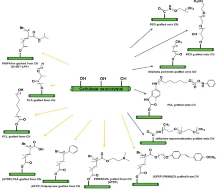
Figure 1.11. Common modification methods used for the surface modification of CNC by polymer grafting (blue arrows = “grafting to”; yellow arrows = “grafting from”). 47
14 1.1.2.4.3 SI-ATRP grafting of polymers on CNC
One of the first publication mentioning the SI-ATRP grafting of polymers on CNC was reported by Zhang, et al. in 2008 (Figure 1.12).57 In this work, PS was successfully grafted on CNC in the presence
of sacrificial initiators: the analysis of the free polymer initiated by the sacrificial initiator provides some indirect information about the structure of the polymer at the CNC surface. Initiator sites were first introduced on the surface of CNC (CNC-Br) by reacting the surface hydroxyl groups with 2-bromoisobutyrylbromide (BIBB) in DMF. The content of Br in the CNC-Br material (determined by the oxygen flask method) was ca. 0.6 wt. %. The SI-ATRP grafting of PS was then conducted on the CNC-Br particles, in the presence of ethyl α-bromoisobutyrate (EBiB) as a sacrificial initiator. The number-average molar mass (Mn = 74,7000 g/mol) and dispersity (1.2) of the grafted PS was
determined by GPC analysis of the cleaved polymer chains (HCl treatment). The weight percentage of PS in PS-g-CNC (68%) was calculated from the weight of cleaved PS and weight of PS-g-CNC. The TGA analysis of PS-g-CNC showed that the thermal stability of CNC was significantly improved by the grafting of PS. The differential scanning calorimeter (DSC) and polarizing optical microscopy (POM) analyses suggested the PS-g-CNC particles self-assembled in both thermotropic and lyotropic states.
Figure 1.12. The preparation of PS-g-CNC by SI-ATRP57
Morandi, G., L. Heath, et al. (2009) also grafted PS by the same SI-ATRP method.46 The Br content in
BIBB modified CNC (CNC-Br) was characterized by elemental analysis (EA). The authors found that the Br content increased with the amount of BIBB and reaction time. Therefore, the grafting density of PS could be controlled by the reaction conditions used in the preparation of CNC-Br. When 52 mL BIBB was used to modify 1 g of CNC (at 70 oC and for 24 hours) in DMF, 70% of the surface hydroxyl
15
analyzing the free polymer produced by the sacrificial initiators added in the medium (EBiB), assuming that the kinetics of polymerization for the free and grafted PS are the same. The Mn measured increased
linearly with the monomer conversion with a relatively low dispersity (1.1), indicating that the living radical polymerization process was well-controlled. The Fourier transform infrared spectroscopy (FTIR), EA and X-ray photoelectron spectroscopy (XPS) analyses also suggested that the weight percentage of grafted PS in PS-g-CNC increased with the Mn of the free PS. The contact angle
measurements showed that the CNC became hydrophobic after the grafting of PS, which allowed increasing its absorption capacity towards 1,2,4-trichlorobenzene.46
To obtain CNC-Br initiators with a high Br content, Olli Ikkala’s group developed a two-step method (Figure 1.13)55 In a first step, chemical vapor deposition (CVD) was used to produce CNC-Br with
about 5 wt% (characterized by EA). In a second step, the Br content was further increased by treating CNC-Br with BIBB in DMF. The final Br content was 15 wt. % and the density of Br initiator sites at the CNC surface was 4.6 per nm2. Poly(tert-butyl acrylate) (PtBA) brushes were then subsequently
grafted by SI-ATRP, with a high grafting density. Starting from this material, the authors also produced hydrophilic PAA-g-CNC nanoparticles, after acid hydrolysis of PtBA-g-CNC (Figure 1.14).
Figure 1.13.The preparation of CNC-Br with high Br content by the two steps method.55 A few other interesting polymers have also been grafted on CNC by SI-ATRP. Zhang’s group published a paper, in which they reported the grafting of PMMAZO, a liquid crystalline polymer.53 The
16
PMMAZO-g-CNC material exhibited thermotropic and lyotropic states. They later extended the reaction to PDMAEMA, a thermo-sensitive polymer exhibiting a temperature-dependent solubility and a LCST in the range 32–53°C (Figure 1.15).58 The PDMAEMA-g-CNC showed temperature-induced
fingerprint texture, the spacing between the fingerprint lines decreasing with the increasing temperature. PDMAEMA-g-CNC was also quaternized with methyl iodide to produce positive charged PQDMAEMA-g-CNC, which had a high affinity for cowpea chlorotic mottle virus.59 Poly(N-isopropyl
acrylamide) (PNiPAAm), one of the most studied thermoresponsive polymers with a LCST of 32 oC,
was also recently grafted on CNC by SI-ATRP.44 In this study, the density and chain length of the
grafted polymer could be tuned by controlling the density of initiator sites and SI-ATRP process, respectively.44 The SI-ATRP has also been recently used to graft block copolymers on CNC.60,61
Figure 1.14. The preparation of PtBA-g-CNC and PAA-g-CNC by SI-ATRP.55
Figure 1.15.The preparation of PDMAEMA-g-CNC by SI-ATRP.58
Despite the interesting results obtained up to now, the indirect characterization of the grafted polymer through the analysis of the free polymer produced by the sacrificial initiator is still controversial, as the
17
kinetics of homogeneous polymerization are not the same with the kinetics of surface initiated polymerization.62-64 To verify if the method is accurate, Morandi and Thielemans prepared
photocleavable CNC-Br initiators.65 After the SI-ATRP grafting of PS in the presence of a sacrificial
initiator, the grafted chains were cleaved by UV-irradiation and analyzed by GPC. Results showed that the Mn of cleaved PS (with a dispersity of only 1.08) was consistent with the Mn of free PS, suggesting
that the polymerization rates of the free and grafted polymers were the same.
1.1.3 The application of CNC
1.1.3.1 Reinforcing agent in polymer matrices
Because of their outstanding mechanical properties and low density, CNC are ideal reinforcing agents for a wide variety of polymer matrices.66,67 In hydrophilic polymer matrices, unmodified CNC can be
used directly, as they are compatible. However, the chemical modification of the CNC surface is generally required to disperse the filler in hydrophobic polymer matrices.68
CNC have been used to reinforce poly(vinyl acetate) (PVAc) and poly(butyl methacrylate) (PBMA) matrices.69 After the incorporation of 15% v/v CNC in the PVAc matrice, the tensile storage modulus
below the glass transition temperature (Tg) of the polymer was remarkably increased from 2 GPa for
neat PVAc to 5.2 GPa. For the PBMA, the tensile storage modulus increased from 0.6 GPa for neat PBMA to 3.8 GPa with the same filler content. The tensile storage moduli of the pristine polymers decreased dramatically above the Tg of the polymers. CNC exhibit excellent reinforcing ability in
polymer matrices above the Tg of the polymers. Above the Tg, the tensile storage modulus increased
from 1.2 MPa to 690 MPa for PVAc after the incorporation of CNC and from 1 MPa to 1.1 GPA for PBMA.
Juho, et al. modified the CNC with p-aminobenzoic acid (PABA) to obtain photoactive PABA-CNC.70
The resultant PABA-CNC was transparent in the visible light range but had a high UV absorption. Therefore, the PABA-CNC was employed as both a reinforcing agent and UV-filter in PVA films, as shown in Figure 1.16. The tensile strength and modulus of PVA films were found to increase with increasing amount of PABA-CNC.
18
Figure 1.16.The tensile strength (a) and modulus (b) of the PVA film reinforced with increasing amounts of PABA; and schematic representation of the UV filtering and reinforcing effect of PABA-CNC (c). 70
CNC have been also used to reinforce inorganic matrices, such as cement paste.71 With the addition of
0.2 vol% of CNC in the cement paste, the flexural strength of the material could be increased by approximately 30%.71
1.1.3.2 Stabilizer for metal nanoparticles
Metal and metal oxide nanoparticles (NPs) have attracted significant attention due to their activities and applications as catalysts, anti-bacterial materials etc.72-76 However, NPs are not stable and tend to
self-aggregate – due to their high surface area – which decreases their performance.77,78 To limit this
19
large specific surface area and stability in water, sustainable CNC are ideal stabilizers for metal nanoparticles.73,78,79
Pristine CNC have been used to stabilize Au-Ag alloy nanoparticles with a diameter of about 3-7 nm.80
For Ag NPs, the sulfate ester groups at the surface of the CNC were found to impact significantly the size of the nanoparticles.81
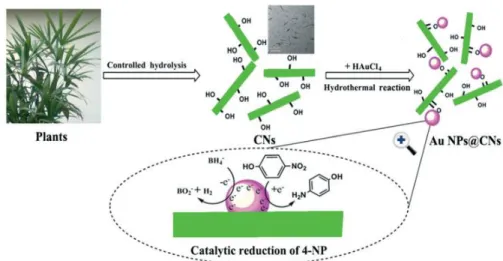
Wu, et al. reported a one-step method to deposit gold nanoparticles (Au NPs) on the surface of CNC without reducing agents, and under hydrothermal condition, as shown in Figure 1.17.82 The CNC were
used as both reducing agents and stabilizers. The resultant Au@CNC supported NPs showed better stability and catalytic performance than the unsupported Au NPs for the reduction of 4-nitrophenol (4NP). The same method was also employed to prepare Pd@CNC supported NPs.83 One of the biggest
advantages of this approach is that no additional reducing agents are required for the reduction of the metal ion. However, the Au or Pd NPs deposited on CNC were bigger than 10 nm (ca. 10-40 nm in diameter).
Figure 1.17. The schematic illustration of the preparation of Au NPs@CNC for the reduction of 4-nitrophenol (4NP).82
To improve the interaction between CNC and NPs and further enhance the stability of NPs, CNC were often modified by polymer grafting or coating. Chen, et al. grafted poly(amidoamine) (PAMAM) dendrimers onto the surface of TEMPO-CNC via the formation of amide bonds to enhance the
20
interaction between the CNC and the metal.72 The PAMAM dendrimers could be used as reducing
agents to reduce the metal ion. When CNC-PAMAM was employed as the reducing agent, the size of Au NPs supported by CNC-PAMAM was in the range of 10-50 nm, and the turnover frequency (TOF) was 2590 h-1. When NaBH
4 was employed as the reducing agent, Au NPs with a smaller size (2-4 nm)
were obtained, and the catalyst systems exhibited even better catalytic activities (TOF =5400 h-1).72
1.1.3.3 Colloid stabilizers in Pickering emulsions
1.1.3.3.1 Pickering emulsions stabilized by CNC
The traditional or classic emulsions are typically prepared with chemical surfactants. Due to the amphiphilic properties of the surfactant, the surface tension between the water and the oil phase is decreased and the emulsion is stabilized. The amphiphilic properties of surfactant can be represented by the hydrophilic-lipophilic balance (HLB). If the HLB of a surfactant is above 7, the surfactant is more hydrophilic and tend to form an oil in water (O/W) emulsion; and if the HLB of surfactant is below 7, the surfactant is more lipophilic and tend to stabilize a water in oil (W/O) emulsion.84 The
classical chemical surfactants are commonly considered as toxic, especially in food, pharmacy, and cosmetic fields.85 Moreover, the residues of surfactant have an enormous impact on the performance of
the final products and their removal is often required for some specific applications. Therefore, alternative surfactants, such as the colloid stabilizers used in Pickering emulsions, have been developed in recent decades.
The emulsions stabilized by colloidal particles, called Pickering emulsions, have been discovered more than one hundred years ago,86,87 but the research on the subject was somehow neglected in the last
century. But in the last two decades, Pickering emulsions have regained interest due to their excellent properties. Pickering emulsions are surfactant-free emulsions, which are more stable and less toxic than the classical emulsions stabilized by chemicals. In these systems, colloidal particles with amphiphilic properties are used. As shown in Figure 1.20, the solid particles used in Pickering emulsions show partial wettability with both the oil and the water phases and are irreversibly adsorbed at the interface between oil and water.85
21
Figure 1.18 The schematic representations of the O/W classical emulsion and O/W Pickering emulsion85
Similarly to the HLB used for surfactants, the three-phase contact angle θow is used to evaluate the
wettability at the solid/oil/water interface (Figure 1.19).88 If θ
ow is lower than 90o, the solid particles
have more affinity with the water phase (they are more hydrophilic), resulting in O/W Pickering emulsions. If θw θow is lower than 90o, the solid particles have more affinity with the oil phase (they are
more lipophilic), leading to inverse W/O Pickering emulsions. If the solid particles are only hydrophilic or only hydrophobic, they will be dispersed in a single phase (water or oil, respectively) and no stable Pickering emulsions will be formed.84,89
22
Compared to the emulsions stabilized by surfactant, Pickering emulsions are more stable. Once solid particles are absorbed at the interface, a high energy is required to remove the solid particles.90 The
required desorption energy is expressed as: ∆E = πr2γ(1 − |cosθw|)2
where r is the radius of the solid particles and γ is the interfacial tension.91
Table 1.3. The summary of colloidal particles used in Pickering emulsifiers84
Both inorganic and organic colloidal particles can be used as stabilizers in Pickering emulsions, such as silica, metal oxide, carbon nanotube, proteins, and polysaccharides, as shown in Table 1.3.84
Polysaccharides, as bio-based materials, are increasingly considered as an alternative to inorganic solid particles, as they are biocompatible and biodegradable. In particular, CNC have recently proven to be efficient for the stabilization of Pickering emulsions.20,49,89,92-94 The pristine CNC produced by sulfuric
acid treatment are not able to stabilize Pickering emulsions efficiently, due to the electrostatic repulsions imparted by the sulfate ester groups at their surface.95 Therefore, salt is generally required
23
CNC extracted from different resources and with different aspect ratios were compared as stabilizers for O/W Pickering emulsions in a recent study.13 The results showed that the aspect ratio of CNC had
a significant influence on the coverage ratio around the oil droplets. As shown in Figure 1.20, a high surface coverage is required for short CNC to stabilize Pickering emulsions, while a lower coverage is sufficient with longer CNC.13
Figure 1.20. SEM images of polymerized styrene droplets stabilized by different types of CNC.13 a, d and g: CNC with small aspect ratio extracted from cotton; b, e, and h: bacterial cellulose; c, f and i: CNC with high aspect ratio extracted from Cladophora
A limited number of O/W emulsions have been stabilized by pristine CNC so far, but chemically modified CNC can be used to extend the field of application. Indeed, the hydrophilic/hydrophobic balance at the CNC surface can be adjusted by chemical modification, which allows stabilizing novel O/W or W/O emulsions. For instance, remarkably stable O/W emulsions of ethyl acetate, toluene or cyclohexane were recently obtained with acetate- or cinnamate-grafted CNC.20 Thermally responsive
polymers such as PNiPPAm have also been grafted on CNC to prepare stimuli-responsive Pickering emulsions.84 The PNiPPAm-g-CNC were able to stabilize O/W emulsions of heptane below the LCST
24
of the polymer. When the emulsions were heated above the LCST, the PNiPPAm-g-CNC particles changed to hydrophobic and the Pickering emulsions were broken.95 Pickering emulsions stabilized by
CNC grafted with PDMAEMA, a pH and thermal responsive polymer, were also recently prepared. The emulsions displayed both pH and thermal responsiveness.49 W/O inverse Pickering emulsions can
also be prepared by grafting hydrophobic moieties at the CNC surface.93 Double Pickering emulsions
systems have also been recently developed with lauroyl chloride modified CNC.94,96
1.1.3.3.2 Application to the elaboration of colloidosomes
The concept of colloidosomes was proposed by Dinsmore, et al. in 2002 by analogy with liposomes.97
Liposomes are capsules composed of phospholipid bilayers, while colloidosomes are capsules composed of colloids with selective permeability (Figure 1.21). The colloidosomes are prepared by Pickering emulsification, using colloidal particles, which are locked together at the interface and form a hollow shell structure. The permeability and mechanical performance of the colloidosomes are highly dependent on the conditions used for their preparation (colloidal particles, solvent, way to lock the colloids…).
Figure 1.21. The SEM images of typical colloidosomes.97
Different routes have been used to prepare colloidosomes, such as thermal annealing, gel trapping, covalent cross-linking, polyelectrolyte complexation, and polymerization of droplet phase, as shown in


![Figure 2.6. Kinetics of the ATRP polymerization of free PS: (A) Monomer conversion and ln([M 0 ]/[M t ]) vs](https://thumb-eu.123doks.com/thumbv2/123doknet/14529738.723373/75.918.116.777.278.536/figure-kinetics-atrp-polymerization-free-ps-monomer-conversion.webp)