Publisher’s version / Version de l'éditeur:
Vous avez des questions? Nous pouvons vous aider. Pour communiquer directement avec un auteur, consultez la
première page de la revue dans laquelle son article a été publié afin de trouver ses coordonnées. Si vous n’arrivez pas à les repérer, communiquez avec nous à PublicationsArchive-ArchivesPublications@nrc-cnrc.gc.ca.
Questions? Contact the NRC Publications Archive team at
PublicationsArchive-ArchivesPublications@nrc-cnrc.gc.ca. If you wish to email the authors directly, please see the first page of the publication for their contact information.
https://publications-cnrc.canada.ca/fra/droits
L’accès à ce site Web et l’utilisation de son contenu sont assujettis aux conditions présentées dans le site LISEZ CES CONDITIONS ATTENTIVEMENT AVANT D’UTILISER CE SITE WEB.
Research Report (National Research Council of Canada. Institute for Research in
Construction), 2005-06-01
READ THESE TERMS AND CONDITIONS CAREFULLY BEFORE USING THIS WEBSITE.
https://nrc-publications.canada.ca/eng/copyright
NRC Publications Archive Record / Notice des Archives des publications du CNRC : https://nrc-publications.canada.ca/eng/view/object/?id=0c4c4ffb-827c-476a-ab60-bb0af82a7c92 https://publications-cnrc.canada.ca/fra/voir/objet/?id=0c4c4ffb-827c-476a-ab60-bb0af82a7c92
NRC Publications Archive
Archives des publications du CNRC
For the publisher’s version, please access the DOI link below./ Pour consulter la version de l’éditeur, utilisez le lien DOI ci-dessous.
https://doi.org/10.4224/20377913
Access and use of this website and the material on it are subject to the Terms and Conditions set forth at
The Design and Construction of Electronic Deflection Gauges to
Measure the Movement of Floor Assemblies in a Fire
The Design and Construction of Electronic Deflection
Gauges to Measure the Movement of Floor
Assemblies in a Fire
Forte, N.; Crampton, G.
IRC-RR-202
June 2005
1
The Design and Construction of Electronic Deflection Gauges to Measure
the Movement of Floor Assemblies in a Fire
Nicolas A. Forte and George Crampton
Abstract
The purpose of this apparatus is to measure the distance that a typical house floor assembly deflects during a fire. The floor structure weakens as it sags with a fire beneath it. It is important to know how much deflection to expect before structural failure occurs. This can be related to the time allowed to safely egress the building. Deflection is the movement of a structure from a fixed position resulting from stress. In this
application, the floor assembly is deflected from its fixed horizontal position as a result of stress from the fire beneath it. Deflection gauges were constructed to measure the distance the floor was deflecting from the fixed horizontal plane located on the floor above the test floor. The method for constructing a deflection gauge is described in this report as well as the electrical circuit used for the measurement, the calibration
procedure, and the test results from an actual fire.
Introduction
For this project, 9 deflection gauges were constructed and installed on the floor above the test floor. The structure contains three levels, a basement, first, and second floor. The floor of the first level was the test floor and fire was in the basement. No deflection was expected on the second level so the deflection measurements were referenced to it. Nine deflection gauges were installed on the second level floor and 9 water filled rigid copper tubes passed through the 2nd floor to the test floor below. The vertical deflection of these columns is translated to a proportional electrical signal by the deflection gauges. The deflection gauges must not be temperature sensitive and should be rugged enough to withstand repeated full-scale fire tests.
.
Circuit Design
The circuit design was based on Kirchhoff’s voltage law where the output voltage of the device is based on the supply current multiplied by the resistance of the wire used for the deflection measurement. The current source was produced by an LM317 voltage regulator set up as a constant current source. This provided a constant current of 10 milliamps to each deflection gauge in a series circuit from the 1st deflection gauge to the 9th deflection gauge.
The circuit diagram is shown in Figure 1. Nichrome ribbon wire ( 0.17 ohms /cm) was connected to the top of the copper tube and passed over a pulley and a fixed post to a 250 gram weight. As the copper tube moves vertically up or down the distance between the fixed post and the weighted end of the wire changes inversely. The
constant current is fed between the fixed post and the weighted end producing an output voltage proportional to the linear movement. .
2
Ceramic insulators were installed inside of the copper tubing held by a bolt. This prevented electrical current from grounding through the metal floor where the deflection gauges were positioned. The output voltage was measured between the fixed post and another terminal connected to the weighted end of the wire.
System Design
In order to produce a rugged deflection gauge, 50 mm x 100 mm rectangular steel tubing was used as the base. An 18 mm hole was drilled through both sides of the metal base making sure that the top and bottom were lined up in the y-axis. This
allowed movement of the copper tube easily without excessive friction drag and prevented any lateral movement that would introduce error.
Angle Iron was cut 254 mm in length and welding onto the side of the base. This provided a strong support for the phenolic resin arm that contained the electrical and
Figure 1. Circuit diagram of the deflection gauge setup.
317 voltage regulatorAdjust
Output Input voltage
120 ohm
10 milliamp constant current source
9 volt battery +
-First Deflection gauge
Last Deflection Gauge
Output voltage to data system
Output voltage Water filled copper pipe
~3 m long Nichrome ribbon wire 0.16 ohms /cm Deflection Tensioning weight 15 cm 15 cm
3
mechanical connections. The 50 mm by 150 mm phenolic resin (Bakelite) arm was bolted to the angle iron so that it hung over the hole of the base.
Copper tubing, 16 mm in diameter was cut 2.5 m long and installed in the
deflection gauges through the floor and rested on the test floor below. The bottom of the tubing was capped at the bottom so it could be filled with water from the top. The water was necessary to provide a heat sink so the tube would not change its length during the test due to heating.
A hole was drilled in the copper tubing at the top and a bolt with ceramic insulators was put through the hole so that nichrome ribbon wire could be anchored to copper tube using a crimp lug.
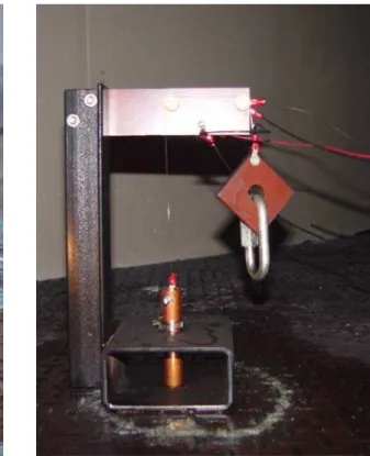
The wire was fed from the copper tubing up through a pulley on the bakelite, over a fixed post and down to the 250 gram counter weight. The weight was used to force good electrical contact between the fixed post and the ribbon wire. The maximum deflection that could be measured with this arrangement was 100 mm. A finished deflection gauge is shown in Figure 2.
Figure 2. Photo of 1 of 9 deflection gauges.
4
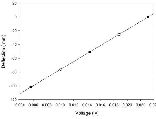
CalibrationThe deflection gauge was calibrated by changing the vertical position of the copper tubing in known increments and then reading the output voltage with a high input impedance volt meter. The results were plotted and are shown in Figure 3.
It was calculated that there was 1.76 mV of output signal per centimetre of deflection and all the deflection gauges had approximately the same calibration.
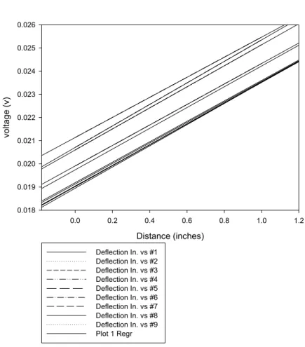
Variations in the initial lengths of ribbon wire produced different intercepts but the slopes were constant as shown in Figure 4.
Voltage ( v) 0.004 0.006 0.008 0.010 0.012 0.014 0.016 0.018 0.020 0.022 0.024 Defle c ti on ( mm) -120 -100 -80 -60 -40 -20 0 20
Equation Deflection (mm)= 5814.83911 * voltage - 134.49879 Rval = .99997
Subtract initial reading from column and multiply by 5814.83911 to obtain deflection in millimetres.
5
ResultsDuring the fire test the deflection gauges functioned smoothly. Since the total resistance of the chain of deflection gauges was less than 100 ohms the noise level was less than 0.02 millivolts. Typical results are shown in Figure 5, showing 3 deflection gauges that were monitoring the floor over a joist section.
Floor Deflection gauges
Distance (inches) 0.0 0.2 0.4 0.6 0.8 1.0 1.2 vol tage ( v ) 0.018 0.019 0.020 0.021 0.022 0.023 0.024 0.025 0.026 Deflection In. vs #1 Deflection In. vs #2 Deflection In. vs #3 Deflection In. vs #4 Deflection In. vs #5 Deflection In. vs #6 Deflection In. vs #7 Deflection In. vs #8 Deflection In. vs #9 Plot 1 Regr
6
A series of photos are shown in Figure 6 to help illustrate the experimental setup.
First Row Time Seconds -200 0 200 400 600 800 1000 Displac e ment ( mm) -100 -80 -60 -40 -20 0 20 #1 #2 #3
Figure 5. Fire test results showing the first 3 deflection gauges.
Figure 6. Photos showing the deflection gauge experimental setup.
Nine water filled copper tubes
positioned over the loaded test floor
Nine deflection gauges setup on
the floor above the test area
7
LimitationIn this project, the copper tubing did not continue measuring the deflection as the floor collapsed. A clamp wrapped around the copper prevented it from falling further. This clamp was necessary to prevent the weight from the copper tubing from loading the ribbon wire when the 250 gram weight reached the contact post. The copper tubing could deflect approximately 80 mm before the clamp hit the edge of the hole of the base. This allowed only 20 mm of movement in the opposite direction. Another limitation was the resistance to heat. The device was proven effective to over 200 Celsius but if it were exposed to higher temperatures the connecting wires would be damaged as well as the phenolic resin arm. This configuration proved adequate for this test scenario. Should it be used in higher temperatures the electrical insulators should be replaced with ceramic components.
Summary
This report describes the design and function of nine deflection gauges used to measure the deflection of a floor that has been exposed to fire from below. The
calibrations, limitations, and data results were discussed. This instrumentation provided important information relating the amount of deflection and the time to collapse of floors in a burning house. These devices will provide useful comparison data between a variety of different floor systems presently being tested in the Fire Performance of Housing Project.
Acknowledgements
The authors would like to thank staff of the Fire Research Lab for their assistance in this project.
References
1. Crampton, G., “The Use of Ni-Chrome Ribbon Wire to Determine the Dimensions of Unconfined Flammable Liquid Spill Fires”, Institute for Research in Construction, Almonte, Ont., 1998.
2. Sears, Zemansky, and Young, “College Physics, fourth edition”, Addison-Wesley Publishing inc.,1974.