An Autostereoscopic Display Using Reflection
Edgelit Holograms
by
Aaron Benjamin Weber Bachelor of Science in Optics University of Rochester, June 1997
Submitted to the Program in Media Arts and Sciences School of Architecture and Planning
in partial fulfillment of the requirements for the degree of
Master of Science in Media Arts and Sciences
at the
Massachusetts Institute of Technology September 2001
@ Massachusetts Institute of Technology, 2001 All Rights Reserved
Signature of the Author -
-Aaron Benjamin Weber Pro Sra h edia Arts/nd Sciences
Certified by
---V
V Dr. Stephen A. BentonAllen Professor of Media Arts and Sciences Thesis Supervisor
Accepted by
a--Dr. Andrew B. Lipman Chair, Departmental Committee on Graduate Students Program in Media Arts and Sciences
MASaCHuuSEtTIS INSTITUTE
OF TECHNOLOGY
oc
1 2 2001
OTCH
An Autostereoscopic Display Using Reflection Edgelit
Holograms
by
Aaron Benjamin Weber
Submitted to the Program in Media Arts and Sciences, School of Architecture and Planning
August 10, 2001, in partial fulfillment of the requirements for the degree of
Master of Science in Media Arts and Sciences
Abstract
This thesis documents the theory and practice of making reflection edgelit holograms, the design of an autostereoscopic display that uses reflection edgelit holographic optical elements, and the evaluation of the autostereoscopic display as built. The theory of hologram formation and reconstruction with emphasis on fringe formation and the K-vector approach to holographic ray tracing is discussed. The physical and biological mechanisms of stereoscopic and
autostereoscopic displays are described, and the details are given for a new autostereoscopic display based on a compound microscope that uses edgelit holographic mirrors (EHMs). The experimental procedure for producing a high-quality EHM is detailed. The performance of the EHM for use in the autostereoscopic display is analyzed and the results are compared to the theory.
Thesis Supervisor: Stephen A. Benton
Thesis Readers
Dr. Stephen D. Fantone President
Optikos Corporation
Dr. V. Michael Bove, Jr. Principal Research Scientist
Acknowledgments
Thanks to:Steve Benton for all his advice and guidance;
Mike Bove and Steve Fantone for their help and teachings;
Elroy Pearson, Wendy Plesniak, Aditya Prabhakar, and Steve Smith for their support and help; Mom and Dad.
Contents
Chapter 1: Introduction... 12
1.1 M otivation and definition ... 12
1.2 Background ... 12
1.3 Purpose... 13
1.4 Outline... 14
Chapter 2: H olography... 15
2.1 Recording a hologram ... 15
2.1.1 Fringe form ation ... 15
2.1.2 Fringe geom etry ... 16
2.2 H ologram reconstruction ... 19
2.2.1 Transm ission hologram s ... 19
2.2.2 Reflection hologram s... 20
2.3 Edgelit hologram s ... 22
2.3.1 D efinition... 22
2.3.2 Fringe structure ... 23
2.3.3 Problem s w ith edgelit hologram s... 24
2.4 Prior w ork ... 25
Chapter 3: Stereoscopic displays ... 28
3.1 M echanism s of seeing in three dim ensions ... 28
3.2 Stereoscopic displays ... 29
3.2.1 Exam ples... 29
3.2.2 Drawbacks of stereoscopic displays ... 30
3.3 A utostereoscopic displays... 31
3.3.1 The com pound m icroscope ... 31
3.3.2 An autostereoscopic display using compound microscopes... 33
3.3.3 A compound microscope with an off-axis parabolic mirror... 34
3.4 An autostereoscopic display using holographic m irrors... 35
3.4.1 System configuration ... 35
3.4.2 A dvantages of EHM s... 36
Chapter 4: Experim ental ... 38
4.1 Initial trial... 38
4.2 M odifications to the exposed hologram ... 40
4.2.1 Change of recording m aterial... 40
4.2.2 Reducing total internal reflection... 40
4.2.3 M odifying the glass substrate ... 42
4.2.4 Reducing additional reflections ... 43
4.3 M odifications to the exposing beam s ... 44
4.3.1 Creating the object beam ... 44
4.3.2 V arying the object beam angle ... 44
4.3.3 M odifying the reference beam ... 45
4.4 Final exposure setup ... 46
Chapter 5: Evaluation of edgelit holographic m irror ... 48
5.1 Testing w ith white light ... 48
5.1.1 System setup ... 48
5.1.2 Results... 49
5.2 Testing with laser light... 51
5.2.1 System setup ... 51
5.2.2 Results... 51
5.3 Analysis of im age properties ... 52
5.3.1 Causes of im age degradation... 52
5.3.2 Ideal reconstruction values ... 53
5.3.3 Grating vector uncertainty ... 53
5.3.4 Im age blur ... 54
5.3.5 Lim ited field of view ... 55
Chapter 6: Conclusion... 57
6.1 Objectives ... 57
6 .2 R e su lts ... 5 7 6.2.1 EHM s... 57
6.2.2 Auto stereoscopic display ... 57
6.3 Discussion and future work ... 58
6.3.1 EHM s... 58
6.3.2 Autostereoscopic display ... 58
Appendix A: Calculations... 60
Bibliography ... 63
List of Figures
Figure 2.1: Transmission hologram ... 17
Figure 2.2: Reflection hologram... . ... 18
Figure 2.3: Steep reference beam angle ... 23
Figure 2.4a: Transmission edgelit hologram ... 24
Figure 2.4b: Reflection edgelit hologram... 24
Figure 3.1 a: W heatstone stereoscope... 29
Figure 3. 1b: Brewster stereoscope... ... 29
Figure 3.2: Magnifying lens... .... 30
Figure 3.3: K eystone stereoscope ... 30
Figure 3.4: Simple compound microscope ... ... 32
Figure 3.5: Autostereoscopic system using microscopes ... 33
Figure 3.6: Off-axis section of a parabolic mirror ... 34
Figure 3.7: Compound microscope with mirror eyepiece ... 34
Figure 3.8: Exposure setup for an EHM ... 35
Figure 3.9: An autostereoscopic display using EHMs... 36
Figure 3.10: Multiple stereoscopic views ... 37
Figure 4.1: Initial EHM setup ... 38
Figure 4.2: Initial problems and solutions ... 39
Figure 4.3: TIR in glass substrate ... - ... 41
Figure 4.4: No glass substrate... ... 42
Figure 4.5: No TIR in glass substrate ... .. 42
Figure 4.6: Exposing directly into glass substrate ... 43
Figure 4.7: Glass in front ... ... 43
Figure 4.8: Varying object beam angles ... 45
Figure 4.9: Final EHM setup ... 47
Figure 4.9a: Double exposure ... 47
Figure 5.1: Setup to test hologram... ... 48
Figure 5.2a: White-light illuminated image of grid when focused at hologram... 49
Figure 5.2b: White-light illuminated image of grid at hologram with aperture ... 49
Figure 5.3 a: White-light illuminated image of grid when focused at infinity ... 50
Figure 5.3b: White-light illuminated image of grid at infinity with aperture ... 50
Figure 5.4: Laser-illuminated image of grid when focused at infinity ... 51
Figure 5.5: Alignment range ... 56
Figure A. 1: Spreadsheet screen capture... 62
Chapter 1: Introduction
1.1 Motivation and definition
Holography is a field with many applications, from the ability to create accurate, three-dimensional representations of fragile objects to the use of holograms as optical elements in heads-up displays for aircraft. However, holograms traditionally have had demanding
illumination requirements. Viewing a hologram of a physical object requires having the proper light at the proper angle each time the hologram is to be viewed, and the image quality of all types of traditional holograms can be diminished by undesired ambient light. A solution to these problems is to illuminate a hologram through its side or edge.
"Edgelit hologram" refers to a type of hologram that is laminated to a clear block made of plastic or glass. One of the beams that is used to record the hologram passes through the block
so that the film is illuminated at an angle that is much steeper than possible if the beam had passed only through air. A hologram that is recorded in this manner must also be viewed with the illumination beam passing through a block. This viewing geometry allows the hologram and light source to be integrated into a single unit, with the lamination block placed on a base that has a light source inside. This is in contrast to a typical traditional hologram, which requires the light source to be carefully located some distance away. In addition, image quality can be kept high by preventing ambient light from illuminating the edge of the block and the hologram.
1.2 Background
Although work on edgelit holograms was first reported thirty years ago, relatively little research has been done on them compared to traditional holograms. The great majority of the work that has been done has been on transmission types-a review of the literature found only one paper from a non-Media Lab source that discussed reflection edgelit holograms in any detail. There has been a small amount of work done by past members of the Spatial Imaging Group at the Media Lab as part of their theses, but the topic of reflection edgelit holograms was addressed only briefly for completeness. As with traditional holograms, edgelit holograms have been used in both pictorial and optical element applications.
There are two major reasons why edgelit holograms have not been a popular research topic. The first is that it is very difficult to make an edgelit hologram with image quality comparable to that of a traditional hologram. The exposing setup is more complicated, and there are numerous technical issues that do not arise when making standard holograms. A second reason is that there is currently no way to replicate an edgelit hologram. The ability to be mass replicated is
necessary for a hologram to be used for more than a prototype display. Therefore, there has not been as much interest in edgelit holograms as there has been in traditional holograms.
Despite the lack of research attention given to edgelit holograms, their integrated nature gives them a clear advantage over traditional holograms. Having the light source and hologram contained in a single unit means that the image can be viewed under ideal conditions simply by pressing a switch to turn on the light source, in contrast to having to carefully illuminate a
traditional hologram with the proper light at the proper angle each time the hologram is to be viewed. This can be simplified by permanently mounting a light source on the wall or ceiling, but this procedure needs to be done anywhere the hologram is to be viewed. Edgelit holograms
also require proper illumination but only need to be aligned once, when the system is assembled. The edgelit hologram and its viewing assembly form an easily portable system with some useful
applications.
1.3 Purpose
As with traditional holograms, edgelit holograms can be recorded in either transmission or reflection mode. A transmission hologram is viewed by passing light through the hologram, and a reflection hologram is viewed by reflecting light off the hologram. A transmission holographic optical element (HOE) is a grating that acts like a lens, while a reflection HOE acts like a mirror. A holographic mirror is made by making a hologram of an actual mirror. The HOEs in this thesis are holograms of an off-axis section of a parabolic mirror, which has the property of collimating without spherical aberration light from a point source.
The purpose of a stereoscopic device is to present different two-dimensional versions of the same three-dimensional scene to the left and right eyes of a human viewer to create the illusion of looking at something in three dimensions. An autostereoscopic display does this without requiring the viewer to wear goggles or glasses or some other type of viewing aid. It is designed to present image depth from a distance. Reflection HOEs have been used in autostereoscopic
devices, but the requirements of traditional holograms make for an awkward device. The integrated nature of edgelit holograms will make possible a better system by allowing for a simple and compact device.
The proposed autostereoscopic device is a dual microscope system, with one microscope for each of the left and right eye images. These images can be either two computer-rendered
perspectives or the output from two video cameras that look at the same object. The images can be provided by fixed pictures or by compact display devices such as liquid crystal displays. A lens is used to form intermediate images of the pictures, and two adjacent edgelit holographic mirrors (EHMs) collimate the light from each image. When a viewer focuses at infinity, one image will line up with each eye. The images will become sharp and will converge to create a three-dimensional scene when the viewer stands at the correct distance from the display.
There are two goals of the work that is described in this thesis. The first is to contribute to the field of holography by determining the necessary exposure conditions for making a high-quality reflection edgelit hologram and by performing a theoretical analysis of the same hologram. The second is to design, assemble, and test a new autostereoscopic display using EHMs.
1.4 Outline
This thesis will document the theory, design, assembly, and evaluation of the proposed autostereoscopic system. The second chapter of this thesis discusses the theory of hologram formation and reconstruction and compares traditional holograms to edgelit holograms. It also contains a summary of the history of the research that has been done on edgelit holograms. The third chapter describes the physics and physiology of stereoscopic and autostereoscopic displays and explains in detail the proposed autostereoscopic display using EHMs. The fourth chapter lists the experimental procedure for producing a high-quality EHM. The fifth chapter evaluates the performance of the hologram made according to the steps in the fourth chapter and compares the results to the theory outlined in the second chapter. In the last chapter, the data in the fifth chapter form the basis for a discussion of the usefulness and the future of the device.
Chapter 2: Holography
Holography is the process of recording and playing back optical wavefronts. A hologram is a recording of the interference of two or more wavefronts. The first two sections of this chapter discuss the recording and reconstruction of a hologram. The third section defines and describes the edgelit hologram, and the last section gives the historic background of holograms and edgelit holograms in particular.
2.1 Recording a hologram
2.1.1 Fringe formationA hologram is made by interfering two coherent beams of light inside a recording medium. Light from a laser is split into two beams, the reference beam and the object beam. When these beams are recombined they form an interference pattern of light and dark fringes, the amplitude of which is recorded in an emulsion. The intensity of the interference pattern is proportional to the square of the total amplitude. The beams can be written in complex notation: U0=O(r)e-'O(r)
and Ur=R(r)e-'(r), where R and
0
are the amplitudes as a function of distance and#r
and#o
are the phases. The intensity is therefore'I =1 U +Ur 12= U |2 +\ Ur 2 +Ur*Uo +UrUo*
= 02 +R2 +U*UO +UU * (2.1)
= 1o + Ir + 2 rcoskp - r ]
where 10 and Ir, the squares of the complex amplitudes, are the intensities of the two beams. When the hologram is re-illuminated with the reference beam the reconstructed beam is formed
C = IU,. =UI + U,I,. + U,U,.*U + UrUU* (2.2)
=U,Io +U,.,. J+ ,.U +U,2U*.
The first two terms are the reference wave modulated by intensities of the two original waves. The fourth term is the modulated conjugate of the object beam. The third term is the desired holographic reconstruction term, the object wave modulated by the intensity of the reference beam. When the hologram is illuminated with the reference beam, typically a plane wave or spherical wave, the wavefront corresponding to the object beam will be output from the hologram along with the phase conjugate of the object beam and some noise.
The object beam is named such because it is modulated by reflecting off or passing through some object before reaching the plate. The complete modulated wavefront is recorded on the hologram and can be played back. Because holograms are made with coherent light, both the amplitude and phase of the object are preserved as shown above, so that the reconstructed object beam contains the full three-dimensional information about the object. If the object is a lens or mirror then the hologram will have the same light shaping properties as that optic and will be a holographic optical element (HOE).
2.1.2 Fringe geometry
A transmission hologram is formed by the interference of two beams that are traveling in the same direction. A transmission hologram of a physical object is viewed on the opposite side as the reconstructing light source. If the illuminating light has the same basic wavefront as the reference beam (C=IUr), then the viewer sees a virtual image behind the hologram of the original object. If the reconstruction wavefront is the phase conjugate of the reference beam (C=IU*), then a real image will be projected. It is in this way that a transmission HOE will act like a lens. One basic example is when two plane waves interfere to form a simple sinusoidal grating. The phases of the two beams are given by2
$(x'y) = 2rx smin O(2.3)
where A is the wavelength of the interfering light and 0, and 0, are the angles of inclination with respect to the horizontal axis of the object and reference beams. Substituting these values into Equation 2.3 with Io=Ir= 1 gives
27r 27r
I(xy)=1+1+2 iIcos -xsinQo -- xsinOj.
= 2+2cos 2x(sinB0 -sinOr)- (2.4)
This represents a sinusoidal variation in intensity where the distance between peaks is
sin 00 - sin Or (2.5)
An example of a hologram formed by plane wave interference is shown in Figure 2.1. The reference beam is incident on the recording medium at 0' and the object beam is incident at 300 .
Figure 2.1: Transmission hologram
The reference beam is refracted inside the hologram according to Snell's Law
ni sin 01 = n2 sin 02 (2.6)
where ni and n2 are the indices of refraction and 01 and 02 are the angles with respect to the normal to the surface of incidence. In this and all future examples, light with a wavelength of
532 nm travels from air (n=1.0) to Dupont photopolymer. The angle of the fringes that are formed by two plane waves is
0f 0, +or (2.7)
2
The perpendicular spacing between the fringes A is given by
A = n (2.8a)
2si 2
CD
=1
-02|(2.8b)
and the vertical spacing between the fringes along the surface of the recording medium is given by
by - d . A A /n
cosr00 +Or 2sin " cos
An2 2 2 (2.9)
A/n sinQ, - sin 6,r
The above case illustrates the fringe formation when the object beam has a single uniform wavefront. When the object beam is more complicated, it can be thought of as the superposition
of a large number of smaller wavefronts. The fringe structure in the hologram is then the superposition of the interference of each wavefront with the reference beam in the manner discussed above. All of the examples in this section show two-plane wave interference for simplicity.
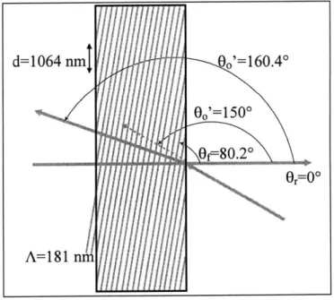
Figure 2.2 shows the fringe structure of a reflection, or Denisyuk, hologram. In this case, the object beam travels in a direction roughly opposite to the reference beam. A reflection of a physical object hologram is viewed with the reconstruction light source on the same side of the hologram as the viewer. If the reconstruction beam has the same phase as the reference beam then a virtual image will be seen. If the reconstruction beam has the conjugate and is incident
from the opposite side then a real image will be projected. It is in this way that a reflection HOE will act like a mirror. For comparison, the object beam is again 300 from normal and the fringes are shown at the same scale. The value of d is the same for both the transmission and reflection holograms, and the fringes bisect the angle between the two beams in each case. However, in a transmission hologram the fringes are nearly perpendicular to the hologram surface while in a reflection hologram the fringes are nearly parallel. Therefore, the perpendicular fringe spacing is much smaller for the reflection hologram in this example and in the general case.
2.2
Hologram reconstruction
2.2.1 Transmission hologramsTransmission holograms act like diffraction gratings with a surface spatial frequencyf,
where2
1 sinQ - sin O (2.10)
f=-d Al
where A1 is the exposing wavelength. This grating then diffracts an illuminating beam with a wavelength A2 that enters at an angle 0, into the output beam, 0, by the grating equation,
sin0, = A2f +sin6,. (2.11)
These two equations can be combined to give the ray tracing equation for transmission holograms, where
sinO, = mLf (sin 00 - sin,)0,+ sin 0,. (2.12)
In Equation 2.12, m=1 for orthoscopic reconstruction and m =-1 for conjugate reconstruction. There is an equivalent equation for distances, where the R-values are the distances to the hologram.
1=
(2.13)
R, ), RO R,. R,'(.3
Because the fringes in a transmission hologram are nearly perpendicular through the hologram, it will act like a diffraction grating and exhibit strong dispersion when illuminated with white light. A small change in the illuminating wavelength can cause a large change in the output angle. The image produced by a transmission hologram must be viewed with a laser because white light illumination spreads out and blurs the image too much to be seen. A solution to the dispersion problem is the rainbow hologram. The real image from a "master" hologram is projected through a slit to the plane of a second, "transfer" hologram. The amount of dispersion in an object hologram is a function of the distance from the object to the hologram. Placing the "object" in the plane of the hologram reduces the dispersion so that the change in wavelength with angle becomes much smaller. Although the slit eliminates vertical parallax, it also further reduces dispersion. The effect is that at any one viewing angle the viewer sees a single color such that the entire visible spectrum is spread out over the full viewing range of the hologram-a
white-light viewable transmission hologram. Multiple colors can be displayed in a single view by making multiple exposures properly registering the resulting holograms.
2.2.2 Reflection holograms
An important characteristic of any hologram is its thickness, or Q-value, which depends on the light wavelength, the grating period, and the physical thickness of the hologram. "Thick" means that the grating period is smaller than the thickness, and "thin" means that the grating has a period that is larger than the thickness. A thick hologram will behave like a three-dimensional diffraction grating, while a thin hologram will behave like a two-dimensional grating. A thick hologram is one where
Q
is greater than 10, as defined by3= nA2 (2.14)
where A is the recording wavelength, t is the thickness, n is the index of refraction, and A is the fringe spacing as defined in Equation 2.8a. When a thick hologram is illuminated, the
reconstructed beam will be subject to Bragg diffraction and depends on the angle and wavelength of the reconstructing beam.
The reconstruction properties can be calculated by defining vectors describing the exposing and reconstructing beams. The fringes in a hologram can be described by a vector, K1, with a
magnitude that is related to the fringe spacing and is perpendicular to the fringes4, in terms of the object and reference beam vectors ko and kr such that
KI = ko -kr (2.15a) 2r K I= 2- (2.15b) A ZKl=f +7. (2.15c) 2
The reconstructing vector, K2, is defined by the illuminating and output vectors ki and kt where
K 2 =k, -k,. (2.16)
For an infinitely thick grating, there will be an output only if
K2 = iKI (2.17)
where the positive case indicates direct reconstruction and the negative case indicates phase-conjugate reconstruction.
These vector equations become more useful when they are decomposed into their component equations, in this case the x- and z-directions, with symmetry applying to the y-direction,
Kx=271n1 21a
Kix = (sin60 - sinOr)intema (2.18a)
Kiz = 27cn(cos 0 -cosr)intem (2.18b)
K = 2 2 sin 6, - sinO, )intema (2.18c)
Kz = 2nn2 (cos0, - cosO, )interai (2.18d)
A
2where n, and A, are the index of refraction of the hologram and the wavelength during exposure and reconstruction. Snell's Law allows the x-direction equations to be converted to external angles, giving the x-axis constraint of
-(sin, -sin i--(sin0, - sinor)eem
A2
A
(2.19)where the negative sign gives a virtual image and the positive sign gives a real image. This is very similar to the corresponding equation as for transmission holograms.
The z-component of the vector equation will be affected by shrinkage of the hologram since it is in the direction of the possible change in thickness. Therefore, the z-axis must take this change into account:
n~2(cos0 - cosO = + It'e(COS -Coso0
( o=- cos.r)intema (2.20)
where ti and t2 are the thicknesses of the hologram during exposure and reconstruction. Equation 2.19 is used to give the direction of the output beam, as with a transmission
hologram. However, for a reflection hologram, Equation 2.20 must also be satisfied. It will give a limit on which wavelengths will be diffracted, given white-light illumination. If there is a change in the thickness or index of refraction of the hologram then the ideal reconstruction wavelength and angle can be found by solving Equations 2.19 and 2.20 simultaneously.
In a reflection hologram, the fringes are nearly parallel to the hologram surface, causing the hologram to act like a dielectric mirror and exhibit wavelength selectivity. A perfect hologram that does not change between exposure and re-illumination and is perfectly reconstructed with
white light will only reflect the exposing wavelength. Other reconstructing conditions would not be reflected at all. This property means that a hologram that has been recorded with multiple wavelengths of light will reflect all of those wavelengths when illuminated with white light. This allows for the creation of a "true color" hologram that accurately reflects the full spectrum of colors.
Because holograms are not infinitely thick, they will not exhibit perfect Bragg diffraction. There will be a range of grating vectors that will be formed, all with the same magnitude but with different angles, such that3
A A_
t 2t sin D (2.21)
2
2.3 Edgelit holograms
2.3.1 DefinitionThere is a maximum in-emulsion angle that a beam can have when passing from air to the hologram because light refracts to a smaller angle when passing from a low index medium to a high index medium. For example, a beam that is incident at 900 on an emulsion with an index of refraction of 1.49 will have an in-emulsion angle of only 42'. In an edgelit hologram the
reference beam passes through a recording block before reaching the emulsion so as to increase the angle of the reference beam. This is done by having the beam enter through a face of the block that is perpendicular to the hologram plane. A fluid with an index of refraction close to that of the block, such as xylene, is placed between the block and the hologram so that the reference beam travels between materials of similar indices of refraction (Fig. 2.3). In this way the film is illuminated at an angle that is much steeper than possible if the beam had passed only through air. A hologram that is recorded in this manner must also be viewed with the
illumination beam passing through a block. This viewing geometry allows the hologram and light source to be integrated into a single unit, with the block placed on a base that has a light source inside.
Glass
Substrate Emulsion
Xylene
Recording Block
Figure 2.3: Steep reference beam angle
Having the light source and hologram contained in a single unit means that the image of a pictorial hologram can be viewed under ideal conditions simply by pressing a switch to turn on a
light source, in contrast to having to carefully illuminate a traditional hologram with the proper light at the proper angle each time the hologram is to be viewed. This can be simplified by permanently mounting a light source on the wall or ceiling, but this procedure needs to be repeated anywhere the hologram is to be viewed. Edgelit holograms also require proper illumination but only need to be aligned once, when the system is first assembled. 2.3.2 Fringe structure
Figures 2.4a and 2.4b show edgelit holograms in transmission and reflection geometries. The object beam is incident at 0' and the reference beam is incident to the entrance surface at 30' for comparison to the fringe structures shown above. One difference between edgelit and traditional holograms is that the fringe angle of the transmission edgelit hologram is greater than that of its traditional analogue while the fringe angle of the reflection edgelit hologram is less. A second, related difference is that the vertical fringe spacing is smaller for edgelit holograms.
0r0=30*
Figure 2.4a: Transmission edgelit hologram Figure 2.4b: Reflection edgelit hologram
2.3.3 Problems with edgelit holograms
These two differences in fringe formation give rise to an important difference between edgelit and traditional reflection holograms. As discussed in Section 2.2.2, reflection holograms exhibit wavelength selectivity. Equation 2.21 can be used to show that the selectivity is greatest when P is close to 1800 (and 6j= 90*). This is typically the case, as shown in Figure 2.2.
However, the fringes in reflection edgelit holograms are inclined away from 90* as shown in Figure 2.4b. This means that there is a much larger range of possible angle and wavelength combinations that can be used in reconstruction. This can be a problem when white light is used, because wavelengths far from those that are desired can be reflected.
An additional difficulty with edgelit holograms is caused by reflections. Whenever light passes from one dielectric medium to another some light is reflected and some light is
transmitted unless the two media have exactly the same index of refraction. To obtain the highest fringe contrast, holograms are recorded with light that is linearly polarized with the electric field perpendicular to the plane of incidence (s-polarization). The amplitude reflection coefficient r, for light that crosses and refracts at an interface is given by6
ni cosO6 - n2 cos2 (2.22)
where the reflected intensity R, is the square of rs. As 01 increases, the value of Rs goes to 1, meaning all light is reflected. Because the reference beam in an edgelit hologram has a steep angle, the greater the difference of the indices of refraction between two surfaces, the more light will be reflected. Therefore, close index matching must be used to prevent the reference beam intensity from being greatly reduced.
An additional reflection effect is total internal reflection (TIR), which can occur when light passes from a higher index of refraction medium such as an emulsion to a lower index medium such as air. The critical angle is defined as the in-emulsion angle that will refract to a 900 angle in air. Light that has an angle greater than this will be reflected back into the emulsion rather than be refracted. Because the reference beam in an edgelit hologram has a steep angle, it can experience TIR and reflect back into the emulsion and interfere with itself and again with the object beam. This causes additional, undesired holograms to be formed that reduce the quality of the desired hologram.
2.4 Prior work
Gabor invented the process of recording and reconstructing three-dimensional information using coherent illumination in 19477'8. It was developed as an improved method of electron microscopy using electron beams to record and a mercury arc lamp to reconstruct the images. His holograms were in-line, where a single beam diffracts around or passes through the object and the modulated and unmodulated parts of the same beam interfere. The transmission hologram as it is known today was developed by Leith and Upatnieks in the 1960s9'10. They extended Gabor's concept by using the recently developed laser for both recording and reconstruction. They also developed the off-axis display hologram by splitting the laser into
separate reference and object beams. In 1969, Benton developed the rainbow hologram", which is a transmission hologram that is viewable in white light. The reflection hologram was invented by Denisyuk in 1958 and published in 196212, although it was not recognized by the community until after Leith and Upatnieks published their work. His original work also used a mercury arc lamp. The first edgelit hologram was made by Lin. He did not follow his 1970 paper3 with any additional work due to difficulties with woodgrain caused by Fresnel reflections.
There were no more publications about edgelit holograms until Upatnieks received a patent on a method for recording and displaying edgelit holograms in 198714. This patent describes the
process of recording a laser illuminated transmission edgelit hologram in detail and the
advantages of edgelit holograms. Upatnieks illustrated two reference beam configurations. In the first, the reference beam illuminates the hologram only once. In the second, the reference beam reflects multiple times inside the block. The patent does not describe any problems with this recording format. A 1988 paper5 showed the results of the method described in the patent
in the form of an edgelit holographic gun sight. In 1992, Upatnieks published a follow-up paper16 on edgelit holograms with short sections on several topics. He discussed ways to increase efficiency by reducing undesired reflections through better index matching and by decreasing scatter. He also described a chromatic dispersion compensator, letting the reference beam reflect multiple times inside the block, and different types of monolithic display systems.
17
The first rainbow edgelit hologram was reported by Birner in her 1989 thesis . She used a three-step process to make edgelit holograms that were viewable with a nearby white light point source. She and Benton received a patent for a multi-color edgelit hologram display in 199218. In 1990, Benton et al. published a paper19 on the rainbow edgelit hologram and introduced the
method of recording an edgelit hologram in a tank of xylene. This greatly reduced unwanted reflections caused by the large index of refraction mismatch between glass and air. In 1991, Farmer et al. published a paper2 0 that reduced the three-step process to two steps as a way of
making holographic stereograms. They also did additional work on the recording tank. Farmer's thesis2 1 discussed the tank and the stereogram process in further detail.
In 1991, Phillips et al. reported their work on edgelit holograms in two papers2 2,2 3. They
noted that the Dupont photopolymer dye will fluoresce under proper conditions and discussed the physical effects involved with this, including the Goos-Haanchen effect as a component of total internal reflection. They also mentioned that shrinkage effects in the silver halide emulsion of an edgelit hologram can cause the image to be visible with external illumination. A follow-up paper was published in 1993 that discussed photopolymer and other material effects in more detail. An additional paper from 199625 focused on fringe contrast in edgelit holograms made in Dupont photopolymer. It included both a mathematical discussion of fringe formation and experimental results.
Huang and Caulfield published multiple papers in 1991. One topic was "waveguide" holograms, where the reference beam reflects multiple times as previously discussed by
28
of the effects on the image of this process. The second topic was reflection edgelit holograms They described their setup but did not provide any analysis of their results except to report that they were successful.
Kubota et al. published a paper in 199229 on work in which they used an edgelit-exposed grating to collimate light for illuminating an edgelit object hologram. They discussed
polarization effects on diffraction efficiency and provided a measurement of the diffraction efficiency of an edgelit holographic grating.
Henrion demonstrated a three-color rainbow edgelit hologram in 1993. Her 1995 thesis30
emphasized the theory of edgelit holograms, including discussions of fringe formation exposure requirements, and polarization effects.
A paper on image blur of edgelit holograms was published by Ueda et al. in 199331. They also made a three-color rainbow hologram and examined image blur of transmission and reflection edgelit holograms. In a 1998 follow-up paper32 they compared the amount of color
and image blur for reflection, transmission, and rainbow white-light illuminated edgelit
holograms. They concluded that rainbow edgelit holograms are better for color applications than reflection edgelit holograms because they have less image blur.
In 1998, Wang et al. published their work3 3 on making edgelit holograms for use as
illuminators in fingerprint recognition systems. They discussed how to preshape the reference beam for exposing directly into the edge of a holographic plate without the use of a large recording block. They also included detailed calculations on the transmissivity of the reference beam into the emulsion for different exposure configurations.
In 1998 and 1999, researchers at Sony Corporation published two papers3 4,35 on a "one-step
edge-lit holographic stereogram printer." This is a method of exposing holographic stereograms in an edgelit format onto holographic photopolymer.
Nesbitt's 1999 thesis36 focused on edgelit holograms as a display format. It included a
detailed discussion of the laboratory techniques and hardware required to make a large format, high-quality rainbow hologram.
Chapter 3: Stereoscopic displays
A stereoscopic display combines two or more two-dimensional images such that a human viewer sees a three-dimensional scene. Hundreds of different systems based on a large variety of concepts have been designed and built since 1832, when Sir Charles Wheatstone invented the first stereoscope. Despite the large variety in designs, every successful system accomplishes the same task, that of presenting a different perspective view of the same scene or object to each eye. An autostereoscopic display creates a three-dimensional scene without the use of glasses or other head-mounted hardware. This chapter discusses the physiology and physics of stereoscopy with some historic examples of stereoscopic systems. The last section proposes a new type of
autostereoscopic display that uses edgelit holographic optical elements.
3.1 Mechanisms of seeing in three dimensions
There are several mechanisms involved in three-dimensional viewing, some of which are object dependent (psychological) and some of which are viewer dependent (physiological), with the assumption that the viewer has two eyes. There are four physiological cues: accommodation, convergence, binocular parallax, and monocular movement parallax. Accommodation is when the eye refocuses to view objects at different depths. Convergence is the ability to fuse the two
images that the eyes see into a single image. Binocular parallax is the change in appearance in an object when it is viewed from different locations. Monocular movement parallax is the viewing of an object from different locations by moving either the head or the object. The psychological cues are retinal image size, linear perspective, areal perspective, occlusion,
shading and shadows, brightness and specular reflection, and texture. The goal of a stereoscopic system is to give the illusion of three dimensions by reproducing these mechanisms.
All of these mechanisms play a part in three-dimensional viewing of real objects, but no stereoscopic display other than a hologram can reproduce all of them. However, some provide stronger depth cues than others. The most important is parallax. When we look at a three-dimensional object, each eye looks at the object from a slightly different direction and sees a different two-dimensional image. The brain then fuses the two images together to create a three-dimensional scene. With real objects, we also have the ability to move our heads around and see a continuously changing set of two-dimensional perspectives.
3.2 Stereoscopic displays
3.2.1 Examples
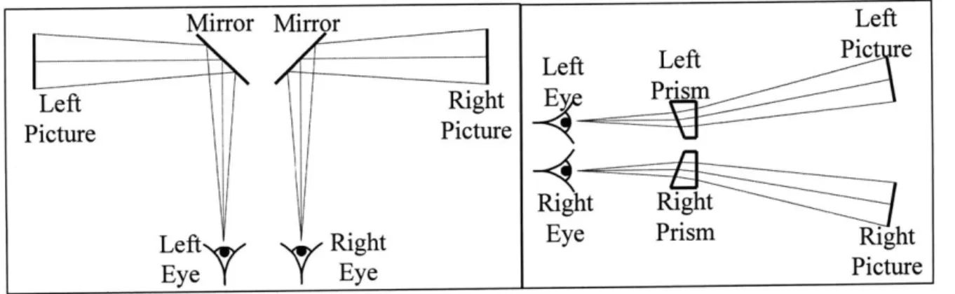
The simplest type of stereoscopic display consists of a single pair of "left" and "right" images placed side-by-side. Each eye sees the two-dimensional image that it would see if the viewer looked at a scene from a single location. Sir Charles Wheatstone invented the image pair stereoscope in 1832. His device used mirrors to send a single picture to each eye (Fig. 3.1 a)37. Sir David Brewster replaced the mirrors with prisms in 1849 (Fig. 3.1 b), and Oliver Wendell Holmes added lenses in 1865. The basic image pair stereoscope using photographs remains virtually unchanged to the present day. There are also devices such as the View-Master@, invented in 1939, which use slides or film rather than photographs.
Mirror Mirror Left
Left Left Pic re
Left Right E Prism
Picture Picture
Right Right
LeftN T Right Eye Prism
Eye Eye Picture
Figure 3.1a: Wheatstone stereoscope Figure 3.1b: Brewster stereoscope One example of a modem stereoscope is the handheld device available from Keystone View. It has two separated five diopter half lenses that act as magnifying lenses. A magnifying lens (Fig. 3.2) works when an object is placed closer to a lens than its focal distance 6. This decreases the divergence of the rays that enter the eye so that they appear to be coming from an object that is larger and farther away than the actual object. The pupil of the eye acts as the aperture stop of the system so that the image of the aperture stop, the exit pupil, is also located at the eye pupil.
Figure 3.2: Magnifying lens
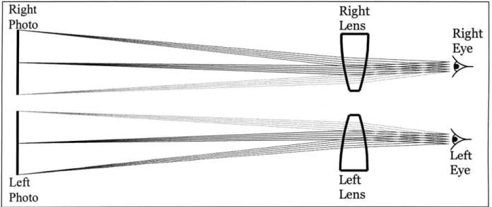
Each half lens in the stereoscope also acts like a prism, shifting the images laterally away from each other. This effect is combined with a divider so that there is no overlap in what each eye sees (Fig. 3.3). The stereoscope is used by centering left and right perspective photographs behind their respective lenses. The viewer then adjusts the distance from the lenses to the pictures until they are in focus. The brain fuses the two images together and the illusion of a three-dimensional scene is created.
Right Right Photo Lens ____ ___ ____ ___ ___Right Eye Photo Lens
Figure 3.3: Keystone stereoscope
3.2.2 Drawbacks of stereoscopic displays
The image pair stereoscope creates a strong three-dimensional image by using binocular parallax along with psychological cues such as occlusion, texture, and lighting. However, there are three major drawbacks to this system. The first is physiological in nature and must always be taken into account.
This system can create a conflict between convergence and accommodation because the photographs remain at a fixed focus while the eyes converge on different depth planes within the scene that is pictured. The conflict gives rise to the "disparity budget," the depth range over which a viewer can look without eyestrain. Scenes with a range of convergence angles of approximately 1.250 can be viewed without the viewer needing to refocus3 7. This angle range
corresponds to different sets of depth ranges (Table 3.1). A stereogram that covers a distance greater than a single range will require the viewer to refocus to see the entire picture.
Far Distance Infinity 24.0' 12.0' 6.0' 3.0' Near Distance 10.0' 7.0' 5.5' 3.8' 2.3'
Table 3.1: Disparity budget depth ranges
The conflict between accommodation and convergence will always exist, but it can be minimized with the use of images that do not have a total depth that is greater than one range shown above. The other drawbacks to the stereo pair system can be eliminated entirely. The first is lack of monocular parallax or "look around" due to the use of fixed images. The user does not see different perspectives when he moves his head. One solution to increasing the number of views is the headmounted goggles that exist for use with computer action games. These goggles have two miniature liquid crystal displays to create a three-dimensional scene that the user can move around in using the keyboard or a joystick. Although this type of system eliminates the fixed view problem it still has a problem in common with the Keystone
stereoscope-they both need to be held up to the head. Other binocular stereoscopic systems such as those that separate the two images by using opposing polarizations or different colors require the user to wear special glasses. Devices that can present a three-dimensional view from a distance without the use of glasses or other user-worn hardware are termed autostereoscopic.
3.3 Autostereoscopic displays
3.3.1 The compound microscope
The first autostereoscopic display, a two-prism cube using total internal reflection, was invented in 1863 by Henry Swan. A large variety of approaches have been implemented since then, including lenticular arrays, raster barriers, slice stacking, and holography.
redesigned so that each eye only sees one image even when the lenses and pictures are at a distance from the viewer. One way to do this is to replace the simple magnifying lens with a compound microscope.
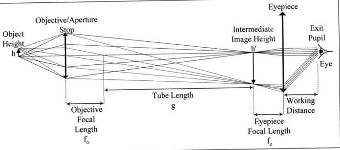
A schematic of a typical compound microscope is shown in Figure 3.4.
Figure 3.4: Simple compound microscope
The objective serves as the aperture stop and creates an inverted, magnified image of the object. The primary magnification is given by
(3.1)
h' g
h f,
The eyepiece collimates the light from the intermediate image and creates the exit pupil. The distance from the eyepiece to the exit pupil is called the working distance. The eye is placed at the exit pupil and the viewer sees a virtual image at infinity. The angle of light exiting the eyepiece is given by
h' hg
fe fo fe (3.2)
The closest distance at which an object can be resolved is the near point, Dv. The angle of light from the object to the eye at this point is
h
n
(3.3) Objective/Aperture Tube Length g Focal Length Eyepiece Focal LengthThe magnification of the microscope is defined by
visual angle of image seen with instrument
visual angle of object seen with unaided eye (3.4a)
hg
_fofe gD,
h (3.4b)
D,
The location of the eye determines the location of the exit pupil formed by a simple magnifier while the location of the exit pupil formed by the compound microscope is
independent of the viewer. Therefore, with a microscope the image of the object can only be seen when the eye is aligned with the exit pupil. This means that microscopes can be used to make an image pair autostereoscope.
3.3.2 An autostereoscopic display using compound microscopes
An example of an autostereoscopic system that uses microscopes is shown in Figure 3.5. Intermediate images of the left and right pictures are formed by a single objective lens. The two eyepieces are separated by the typical human interpupilary distance, and the focal lengths of the eyepieces and the objective lens are chosen to give the desired magnification and working distance. The viewer aligns his eyes with the exit pupils of the system and accommodates to the at-infinity images. The images then fuse together and the viewer sees a three-dimensional image.
3.3.3 A compound microscope with an off-axis parabolic mirror
The above figure shows a microscope-based autostereoscopic display that uses all lenses. This system can be modified by replacing the eyepieces with mirrors, particularly off-axis parabolic mirrors sections. An off-axis section of a parabolic mirror has two advantages over a
lens. The first is that mirrors do not add any chromatic aberration to a system. The second is that a point source that is placed at the focus of this type of mirror will be perfectly collimated at an angle that depends on from which section of a full paraboloid the mirror was taken as shown in Figure 3.6.
Figure 3.6: Off-axis section of a parabolic mirror
This collimation property makes these mirrors suitable for use in a microscope as shown in Figure 3.7. Here the mirrors reflect at 150 because when a point source is replaced by an
extended image, aberrations are introduced. However, these are at a minimum at small angles so that the mirror is still an effective replacement for a lens.
3.4 An autostereoscopic display using holographic mirrors
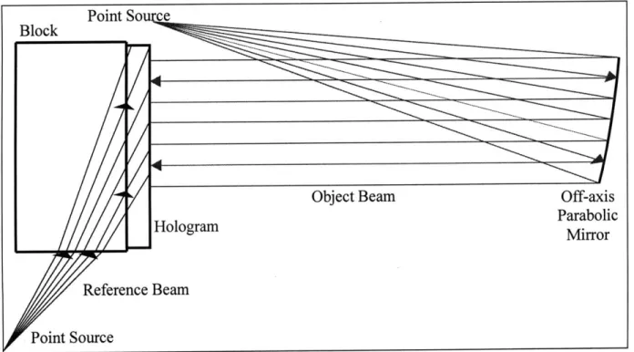
3.4.1 System configurationThe display shown in Figure 3.5 can be modified by using edgelit holographic mirrors (EHMs) rather than traditional mirrors. A schematic of the necessary exposure setup is shown in Figure 3.8
Point So ce
Object Beam Off-axis
HologramParabolic Hologramirror
Reference Beam
Point Source
Figure 3.8: Exposure setup for an EHM
The reference beam, which passes through a glass block to the hologram, is formed by a point source. The object beam is light that has been collimated by an off-axis parabolic mirror. When this hologram is reconstructed with a point source at the location of the reference beam point source, the reflected light will be collimated. If the image of an extended object is placed at the location of the reference beam point source then the entire image will be collimated and an exit pupil will be formed as shown in Figure 3.7.
Figure 3.9 shows the path for one eye of a dual-microscope-type autostereoscopic display that uses EHMs that have been exposed as shown in Figure 3.8. The left and right images are displayed on a backlit LCD. An LCD is used to provide dynamic images that can be controlled by a computer. A lens is used to form an intermediate image of the LCD at the location of the reference beam point source, and the viewer's eyes are placed at the exit pupil of the system.
Hologram |
Figure 3.9: An autostereoscopic display using EHMs
3.4.2 Advantages of EHMs
There are many advantages to using an edgelit hologram for the mirror shown in Figure 3.7. The first advantage of holographic mirrors is flexibility. Having a large working distance microscope requires using a long focal length eyepiece or mirror. This adds length to the distance between the objective and the eyepiece since the intermediate image needs to be at the focal length of the eyepiece. In contrast, a holographic mirror will collimate an object or focused image that is the same distance from the hologram as the point source of the reference beam was when the hologram was exposed. This allows the distance between the objective and the
eyepiece to be shortened by using a short reference beam distance. An EHM also has flexibility in its reflecting angle. Edgelit holograms redirect light at a very steep angle. This allows the 150
off-axis parabolic mirror shown above to be converted to a near-90* off-axis parabolic mirror that has the same low aberration properties of the original. This angle change and short distance from the intermediate image to the hologram can be used to create a much more compact system than one that used physical mirrors. A tabletop unit can be designed where all of the optics are placed in a base below the hologram.
The second advantage of using holographic mirrors is the ability to multiplex. The above discussions of image pair stereoscopes only include one pair, but the system in Figure 3.9 is not
restricted to a single three-dimensional view. Several interlaced pairs can be used to give the user the ability to move among multiple views. This can be accomplished with a single objective lens but requires a separate eyepiece for each view. A large number of views in a small space would require impossibly overlapping lenses or mirrors. However, it is possible to overlap holograms so that several views could be spaced close together with holographic mirrors (Fig. 3.10). Hologram Left I Left 2 Right 1 -~ Right 2
Figure 3.10: Multiple stereoscopic views
The third advantage is that if the holograms do not reflect at 100% efficiency they will be partially transparent. If they do not have an opaque backing then the viewer will be able to see both the image reflected by the mirrors and the real-world scene in front of him. This effect can be used to overlay the scene with information or another view of the same scene but with
different objects. The fourth advantage is reproducibility. Off-axis parabolic mirrors are expensive. However, once a hologram is made of a mirror that hologram can be cheaply copied for mass production. The fifth advantage is that an EHM will only reflect light that enters through the edge of the viewing block. This property is a good way to prevent stray light from being imaged by the system.
Chapter 4: Experimental
There is a limited amount of both published and anecdotal information available about reflection edgelit holograms. Therefore, a series of experiments was performed to determine the optimal exposure configuration for reflection edgelit holograms with the goal of making the hologram required for the display discussed in Section 3.4. The initial successful setup that was used to make an edgelit holographic mirror (EHM) is shown in Figure 4.1. After this hologram was made, every part of the setup was modified or studied to increase the efficiency and image quality of the hologram. The areas that were investigated are described in the following sections. The last section describes the final exposure conditions.
4.1 Initial trial
In every case, a frequency doubled Nd:YAG laser radiating at 532 nm was used. In the initial trial, the recording material was a holographic plate from HRT GmbH, type BB-520. The plate was indexed matched to the recording block using xylene with the emulsion facing out. The reference beam and object beam intensities were in a ratio of 1:1. The reference beam was perpendicular to the object beam and the object beam was incident on the recording block at 18* so that the in-hologram angle was 120 (Fig. 4.1).
This initial exposure suggested a few modifications that could be immediately taken to improve the image quality of the holograms. The first was to eliminate all stray light coming from the reference beam. Light that entered through the edge of the plate experienced total internal reflection (TIR), creating a second reference beam and a second hologram. Light that was incident on a corner or edge of either the plate or the recording block diffracted and
scattered into the hologram, decreasing the efficiency. The best results were obtained when the reference beam was stopped down so that it passed only through the middle of the recording block to the plate (Fig. 4.2).
Internal reflection at the back of the recording block also caused additional holograms to be exposed. When recording a mirror the collimated object beam reflected off the back of the recording block and passed back through the hologram. The reflected beam interfered with the forward traveling object beam and created an in-air viewable plane mirror. This reflection was greatly reduced by index matching light absorbing gray glass to the back of the block.
Glass Substrate Emulsion Xylene Recording Block Beam Block +-Gray Glass
4.2 Modifications to the exposed hologram
4.2.1 Change of recording material
The next change was to use Dupont holographic photopolymer instead of the HRT silver halide emulsion. The HRT plates were first used even though Dupont holographic photopolymer has been shown to be better suited than silver halide plates for making edgelit holograms. This is because the HRT plates were cheaper and easier to obtain than the photopolymer and were more sensitive by two orders of magnitude. However, the HRT plates had a wide variation in plate-to-plate sensitivity and in coating uniformity over a single plate-to-plate. These problems made it very difficult to obtain consistent results, so the recording material was changed to photopolymer. The photopolymer used with green light was type 750x313-20 (750).
The Dupont photopolymer is a tacky substance. It is deposited on a Mylar substrate and is shipped with a second Mylar cover sheet. It is typically exposed by removing the cover sheet and laminating the photopolymer to a piece of glass to provide stability and ease of handling. The front cover sheet must also be removed because it exhibits birefringence that lowers the holographic fringe contrast by affecting the linear polarization of the laser beam used for recording.
4.2.2 Reducing total internal reflection
The 750 film is designed for use as a master for transferring holograms and the Mylar substrate is intended to be removed after the hologram is exposed. However, better results were obtained when the substrate was removed before exposure. When the reference beam entered the Mylar substrate after passing through the photopolymer it experienced TIR at both the Mylar-glass and Mylar-photopolymer interfaces. Therefore, a portion of the reference beam bounced back and forth inside the Mylar and interfered with itself, creating a light and dark woodgrain pattern. This pattern was then transferred to the hologram by the reference beam. Removing the substrate before exposing the photopolymer eliminated this problem. To protect the
photopolymer from the xylene the glass substrate was index matched to the recording block. Photopolymer laminated to a glass substrate is equivalent to a silver halide emulsion on a glass plate and was the way the photopolymer initially replaced the HRT plates. The similarity of the two types of holograms led to each type having the same problem. After passing through the glass substrate and the recording material the reference beam experienced TIR at the
hologram-xylene interface and bounce back and forth (Fig. 4.3). The amount of light reflected at each surface was small but was enough to cause several undesired holograms to be recorded.
Figure 4.3: TIR in glass substrate
The glass substrate was eliminated to eliminate the extra exposures. After the cover sheet was removed, the Mylar substrate was index matched directly to the recording block (Fig. 4.4). This prevented the TIR inside the glass but caused a more serious problem. Without the weight and support of the glass, the photopolymer was so light that it did not lie flat against the
recording block. The variations in distance through the xylene from the block to the
photopolymer were enough to cause interference inside the xylene layer, creating dark and light areas in the reference beam. This brightness variation was then transferred to the exposed hologram giving it a mottled appearance. An attempt to give more structure to the photopolymer by stretching it on a frame was unsuccessful. The problem with this setup led to the
Figure 4.4: No glass substrate
4.2.3 Modifying the glass substrate
Because the glass could not be eliminated, it was modified so that the TIR of the reference beam would not cause multiple exposures. Initially 4"x5" silver halide holographic plates were used as substrates after being soaked in chlorine bleach to remove the emulsion. Each plate was cut in half so that each hologram measured 4"x2.5". These plates were replaced by 0.75" thick window glass that was cut into the same size pieces. The thickness of the glass was selected so that the reflected reference beam did not pass back through the photopolymer (Fig. 4.5). While this was the only intended purpose of using such a thick substrate, the thickness led to another change in the setup.
ad=:bw 4 Photopolymer Glass Substrate - Xylene Recording Block
Figure 4.5: No TIR in glass substrate
The thick glass substrate was thick enough both to prevent double exposures and to accept the reference beam directly. One problem with index matching an edgelit hologram to a recording block is that light is reflected at the liquid interface, reducing the amount of light that reaches the hologram. A second problem is that holograms can only be viewed by light that
.Photopolymer Xylene
reproduces the reference beam used for exposure. An edgelit hologram that is made while index matched to a recording block can only be seen when it is index matched to a viewing block. An edgelit hologram that is recorded with the reference beam passing directly into the glass substrate does not have these problems. The holograms were exposed while index matched to a table-mounted piece of gray glass that served as a plate holder and absorbed the object beam (Fig. 4.6).
Photopolymer
Subs te
Gray Glass
Plate Holder
Figure 4.6: Exposing directly into glass substrate
4.2.4 Reducing additional reflections
Holograms exposed as shown above still had a weak but significant red reflection when illuminated by white light through the side of the glass opposing the substrate. The reference beam interfered with itself inside the photopolymer after experiencing TIR at the photopolymer-air interface. The fringes formed by this interference were similar to those formed by the object beam interfering with itself as shown above. This reflection was defeated by index matching a thick piece of glass to the photopolymer (Fig. 4.7). Exposing directly into a photopolymer-laminated thick substrate with gray glass behind it and thick, clear glass in front eliminated all internally reflected beams and undesired gratings.