A Bicycle Electric Assist Unit
by Arthur Petron
B.Sc. Massachusetts Institute of Technology 2008
Submitted to the Program in Media Arts and Sciences, School of Architecture and Planning,
in partial fulfillment of the requirements for the degree of Master of Science
at the MASSACHUSETTS INSTITUTE OF TECHNOLOGY September 2010
@Massachusetts Institute of Technology 2010. All rights resprrr)
Author:
MASSACHUSETTS INSTITUTE OF TECHINOLOCDYSEP 1
4
2010
LIBRARIES
ARCHNES
/
V(ggfam in Media Arts and Sciences September 2010
Certified by:
Professor Mitchel Resnick on behalf of Professor William J. Mitchell Professor of Media Arts and Sciences Program in Media Arts and Sciences Thesis supervisor
Accepted by:
Professor Patricia Maes Professor of Media Arts and Sciences Program in Media Arts and Sciences
AuthoT,
A Bicycle Electric Assist Unit
by Arthur Petron
B.Sc. Massachusetts Institute of Technology 2008 Submitted to the Program in Media Arts and Sciences,
School of Architecture and Planning,
in partial fulfilment of the requirements for the degree of Master of Science
at the MASSACHUSETTS INSTITUTE OF TECHNOLOGY September 2010
@Massachusetts
Institute of Technology 2010. All rights reserved.ABSTRACT
The BEAU is an electric-assist bicycle system that is completely self-contained within the rear wheel. The purpose of approaching a electric-assist bicycle in this manner is two-fold: simplifying the device and opening the method of implementation to more creative uses. The project requires a large amount of knowledge from many fields. Based on the limits of research, the project will show the aspects of the BEAU's design and how they meet the overall design goals of the project. The BEAU is made up of several parts, none of which include a bicycle. The design of the BEAU takes the bicycle and rider into account only for aesthetic and control reasons. Inside the BEAU reside a custom motor, closed loop controller with power electronic drive elements for the motor, battery pack with custom battery management circuitry, and torque and rotary position encoders. The simplification of both the device required to electrify a bicycle and the user input required to control such a device is intended to make the BEAU a very attractive electric bicycle conversion alternative that can be used not only for consumer uses, but also in situations of mass utilization, such as a bike sharing program.
This research was completed entirely within the Smart Cities group by the author. The original concept of the BEAU was arrived at during a meeting with the late William J. Mitchell as the "GreenWheel" and the project was begun as a team effort with Michael T. Lin, also of Smart Cities. The BEAU manifestation is entirely of the authors design with the purpose of investigating some of the more theoretical aspects of the GreenWheel concept.
Thesis supervisor:
Professor William J. Mitchell
Professor of Media Arts and Sciences
A Bicycle Electric Assist Unit
by Arthur Petron
Thesis reader:
Dr. David Wallace
Professor of Mechanical Engineering
MIT Department of Mechanical Engineering
", f,(-)
A Bicycle Electric Assist Unit
by Arthur Petron
/
Thesis reader:
1
vProfessor Hugh M. Herr
Associate Professor of Media Arts and Sciences
ACKNOWLEDGEMENTS
William J Mitchell The guidance of Professor Mitchell over the past two and a half years have
been an invaluable experience that has taught me much about the world in which we live. I am honored to have had the chance have known Bill.
Hugh Herr and David Wallace My readers were very helpful throughout my term in working
with the BEAU. Their advice and guidance is much appreciated.
David Parks Professor Parks was kind enough to review some of the more intricate methodologies
of beam theory, allowing the flexure analysis to remain as closed form as possible.
Martin Culpepper Professor Culpepper was kind enough to steer me in the correct direction at
the beginning of the flexure design process.
Alex Slocum and Julio Guerrero Professor Slocum and Dr. Guerrero were helpful during the
beta prototype design phase in helping to keep designs manufacturable inexpensively and easily.
Tim Robertson and Irene Zhou My UROPs have been a wonderful help right when I needed
it. They both have worked diligently this past term and summer.
Grant Elliott Thanks for attempting to keep me from digressing too far from the topic at hand
when I come to you about something only slightly tangentially related to my thesis work asking questions.
Sam Duffley, Chris Pentacoff, Emily Obert, Andy Marecki, Kashika Sharma, Josh Siegel, Steve Sprague at Proto Laminations, Tom Lutz, John DiFrancesco, Becky Kusko, Caroline Figgatt, Nadya Peek
CONTENTS
1 Introduction
1.1 Meet the BEAU ... ... 7
1.1.1 How the BEAU works ... ... ... 8
1.1.2 Inside the BEAU ... ... 9
1.2 The BEAU and electric bikes ... 10
1.2.1 Control Methods and Physical Size ... ... 10
1.2.2 Motor Output Power ... ... 11
1.3 Goals of the BEAU . . . . 12
2 The Design of the BEAU 15 2.1 Encoder Placement . . . .. . .. . . . 16
2.1.1 The M agnetic Encoder . . . . . . . . . 17
2.1.2 The Optical Encoder . . . .. 17
2.2 Casing Torque and Force Analysis . . . . 18
2.3 Internal Assembly . . . .. . . . .. . . . . . 18
2.4 A esthetics . . . .. . . .. . - - - . . 20
3 The Motor 23 3.1 M otor Design Basics . . . . .. - . . . 23
3.1.1 Air Gap Flux Density . . . . 23
3.1.2 M otor Torque . . . . 25
3.2 Theory Analysis and Verification . . . 26
3.2.1 FEA Results - Graphs . . . . 26
3.2.2 FEA Results - Plots . . . . 29
4 Control of the BEAU 31 4.1 Control A pproach . . . . 31
4.1.1 Torque Sensor Selection . . . . 32
4.1.2 System Dynam ics . . . . 33
4.2.1 The Electrical Equations . . . .
4.2.2 The Dynamic Equations . . . . 4.2.3 The Closed-Loop Controller . . . . 4.3 Control Hardware . . . .
4.3.1 Controller Inputs and Outputs . . . . 4.3.2 The Control Board and Components . . . . .
5 The Torque Sensor
5.1 Introduction to Flexures . . . .
5.1.1 Advantages of Flexures . . . .
5.1.2 Disadvantages of Flexures . . . .
5.2 The Radial Flexure Design and Theory . . . .
5.2.1 Physical Envelope Definition . . . .
5.2.2 Basic Beam Theory . . . .
5.2.3 Cartesian Beam Bending Due to Rotation . .
5.2.4 The Effects of Shear and Strain . . . .
5.2.5 Fully-Stressed Beams . . . .
5.3 Radial Flexure Fabrication . . . .
.. . . . . - . 3 5 . . . . 3 6 .. . . . . . . . . . . . 3 7 - - - . . . . 3 8 .. . . . . 3 9 ... . . . . 4 2 47 . . . - - . - - - - 4 7 . . . .- -.- . 4 8 . . . . 4 8 . . . .- 4 9 . . . . 5 0 . . . . 5 0 . . . . 5 2 . . . . 5 5 . . . . 5 7 . . . . 5 8 6 Evaluation and Conclusion
1.0. AN
INTRODUCTION TO THE BICYCLE ELECTRIC ASSIST UNIT1.1. MEET THE BEAU
Today, the term electric bicycle is brings a well-understood concept to mind. A bicycle with some combination of electric motor and batteries provides complete or partial motive power to the rider. Nation-wide more than 200,000 electric bikes (e-bikes) are sold each year [10]. They are rapidly gaining in popularity especially in urban areas because of rising fuel prices, limited parking spaces, and daily traffic congestion. Ranging in price from $300 to well over $5,000, the variety of e-bikes for consumers is quite large[22].
Despite their popularity, e-bikes remain in the technological realm akin to the first cellphones; a headset connected by a wire to a large box containing electronics and batteries. The physical design and layout of most e-bike systems necessitates the use of a particular bicycle, and those that do not require the addition of bulky battery packs on the frame or over the wheel to power the crank-shaft or wheel mounted motor. Just as moving the cell phone to a single, hand-held device transformed it from a semi-portable, briefcase sized device to a pocket item, an electric bike whose components resided only where necessary has the potential to revolutionize the market by removing the restriction of bicycle type and allowing for creative mobility architectures that otherwise would not be possible.
The bicycle electric assist unit (BEAU) developed with the Smart Cities group under professor William J. Mitchell is a fully self-contained electrically powered torque assist unit for use with bicycles. It attaches inside the read wheel of a standard bicycle (road or mountain style) and it ridden just like a normal bicycle. The BEAU is similar to common electric bicycles and electric bicycle kits that are currently on the market in the gross end result of its interaction with the user, however the BEAU aims to solve several problems with electric bicycle (e-bike) systems that are currently on the market in order to make the e-bike a more commonly used vehicle - ideally a vehicle that becomes preferred over a gasoline powered vehicle for certain types of trips.
While fully self-contained system does imply the independence from any input, the BEAU does have an external charging port for quick recharge, as well as a data port for diagnostics, firmware upgrades, and behavior programming. These temporary electrical connections aside, during normal operation the BEAU requires no other modification, addition, or subtraction to its host bicycle beyond the wheel to function properly. The BEAU has no ON/OFF switch, no external battery packs, no hand-grip controls, no set-up procedures, and no calibration. Just get on and ride.
Figure 1.1: A depiction of the BEAU in its intended use scenario.
1.1.1. How THE BEAU WORKS
The BEAU works by measuring the rider's torque input to the bicycle and providing a ratiometric assist torque from the motor. The rider and motor act in parallel to the wheel. This means that both the rider and motor have a direct coupling to the wheel, however the rider's coupling is unidirectional due to the presence of a freewheel sprocket on the BEAU hub's chain drive.
A parallel drive has several benefits, but also presents certain control difficulties. One of these
difficulties manifests by requiring that the motor assist torque never be higher than the torque that the rider supplies to the wheel at any given time without freewheeling the bicycle and consequently driving the bicycle with no power input from the rider. While riding under only motor power may be a desired effect in certain situations it causes a lack of control and "feel for the road" that is offered by bicycle riding. In general motoring without pedaling turns a bicycle into an electric scooter.
Although the motor torque can never be higher than the rider input torque, this still accounts for an effective doubling of the rider's input power at the road. This tight control of input versus output allows the rider to feel a direct connection with the road and bicycle - almost as if the electric assist were not present. A BEAU equipped bicycle should feel like a bicycle in low gear that goes the speed of a bicycle in high gear. The ability to ride faster, or at the same speed with less effort while maintaining the feel of an unmodified cycling experience is the goal of the BEAU.
1.1.2. INSIDE THE BEAU
The main components of the BEAU are as follows:
1. Motor - 800W peak, 24-slot, 32-pole, three-phase, frameless, brushless DC torque motor
(BLDC motor).
2. Batteries -39.6V nominal (40V peak) 4.6Ah battery pack - 182Wh with nominal charge.
3. Battery Management -12 cell balancing, charging and protection circuitry.
4. Motor Control - Closed loop control of the motor from sensors to PWM drive signals.
5. Torque Sensor -Flexure-based torque sensing of the rider's input power
The motor is a custom designed actuator to provide the high torque constant required by the BEAU without the need for gearing. It resides in the outermost region inside the BEAU's casing - which incidentally is also the motor casing. The 800W peak power output is just over 1 horsepower. The motor is designed to run at 300 rpm at a torque consistent with the torque required to move a bicycle and rider through the air at that speed on level ground. The actual peak speed of the
BEAU may vary depending on chain gearing and tire size.
The batteries in the BEAU are 3.3V 2.3Ah lithium-nanophosphate cells made by A123 Technologies. They offer very high cycle life and extremely high power density, allowing for high peak currents and high charge rates. A123 cells also have adequate heat tolerance and safe heat response which make them ideal for placement inside the motor casing where temperatures may reach above ambient levels.
Battery balancing, management, and control is handled by a custom printed circuit board (PCB) powered by an Atmel ATMEGA168 microprocessor and a pair of Intersil Technologies battery balancing integrated circuits. The circuit is able to report statistics such as battery health, charge level, discharge rate, etc to the BEAU's main control system. Battery management is necessary to prevent the cells in the BEAU from becoming charged unequally.
Using a torque request by the user, the motor control system consists of a custom printed circuit board driven by an Atmel ATMEGA165PA microprocessor in conjunction with an Allergro Mi-crotechnologies A4935 automotive MOSFET driver integrated circuit. The PCB handles sensor input processing and conditioning, power switching for motor phasing, and closed loop control between the requested torque and the output torque of the motor.
In order to get an accurate torque request from the user, the BEAU implements a flexure-based torque sensor that is located between the freewheel and the motor casing. In this location the sensor is able to measure only the torque the user is putting into the bicycle by being outside of the motor to wheel force tree.
1.2. THE BEAU AND ELECTRIC BIKES
Current electric bicycles that are on the market can be classified into two categories: bike modifi-cations and custom bicycles. Bike modifimodifi-cations usually come in the form of kits for purchase that the consumer can use to convert his or her already existing bicycle into an electric bicycle. Custom bicycles are full bikes that have built in components that cannot easily be made into a kit. The
BEAU falls into the kit e-bike category. A comparison of the BEAU versus other e-bikes that are
currently on the market can be seen in Table 1.1. To note are the bolded entries in the table. Table 1.1: This table depicts the BEAU in comparison to the BionX, Schwinn, GreenLine and UltraMotor electric bicycles.
2500 800
2000
0o800
15-25 miles 25-30 mi 20 mi 20 mi 800W 500W 180 W 250W 500W *s No No No No 30 mph 25 mph ?? 15 mph 20 mph Ws No No No No *s No No No NoWS No Yes Yes Yes
WWs No No No Yes
No No No No No
30
15 minutes ?? 0 ?? 3.5 Hours
minutes
1.2.1. CONTROL METHODS AND PHYSICAL SIZE
In terms of control, both kit and custom e-bikes rely on some sort of throttle for motor input. Some even feature a type of cruise control. The end result of all of these motor power input methods is the transition from a bicycle to a scooter. It is the goal of the BEAU to add to the bicycle riding experience in a way that makes riders feel as though they are still riding a device that behaves just like a bicycle. The reason for this goal (aside from the obvious: form follows function) is based on the learning curve associated with learning how to ride a new type of mobility device. An electric assist system which mimics the function of a normal bicycle will not require any new knowledge to use properly. It looks like a bike; it functions like a bike.
Figure 1.2 shows one disadvantage to current electric bicycle kits. Aside from the fact that many of them use sealed lead-acid batteries for energy storage - causing undue weight increase, these kits add many external components to the frame of the bicycle. In some cases these extra components can change the riding characteristics of the bike by adding a large mass to the bicycle or taking up
ElectcRidr 628 N 2nd St Lawrence, KS 66044 electririder.com Twist Throttle Cruise Control ElecticRide 628 N 2nd St Lawrnce, KS 66044
Brake inhbits induded with crumise coi eecrcider.com
Figure 1.2: This is a good representation of the typical e-bike kit contents. In order to transform an existing bicycle into an electric bicycle, the wheel must be re-spoked with the new hub motor and the rest of the components must be mounted and wired to the frame of the bike.
space that was needed for another function.
In the case of non-kit e-bikes, the frame of the bicycle is usually modified in order to contain the batteries and electronics required for electric assist. While this does solve the frame infringement issue of the kits, the need for a custom designed bicycle is often more costly. Non-kit e-bikes are aesthetically functionally superior to kit types, but they still suffer from the same control scheme used in almost all electric bikes.
The closest bicycle that is comparable to the BEAU in functionality is the Giant Twist Freedom DX (pictured in Figure 1.3. It uses an integrated torque sensor to measure the rider's input torque in a similar way to the BEAU. In this way it acts to supplement the rider's pedal power rather then to replace it. The Giant Twist features a 18Ah, 24V battery pack consisting of 2 9Ah lithium-ion battery packs on either side of the rear wheel. The 250W drive motor is located on the front wheel. This is a good example of the state-of-the-art for an electric bicycle of this type.
1.2.2. MOTOR OUTPUT POWER
The amount of energy a rider must put into his or her bicycle changes with several environmental factors. The two larges factors that change the energy required to move forward at a selected speed are wind and terrain slope. On a windless day the air resistance is fairly small unless the rider is traveling at higher speeds. The difference between slope and wind speed becomes immediately apparent during hill climbing. The energy increase for a change in speed on a slope generally increases much more steeply than for simply a change in wind speed.
Figure 1.3: The Giant Twist Freedom DX Electric Bicycle. In terms of currently on the market electric bicycles, this is a good example of the state-of-the-art.
This effect can be seen quite easily in Figure 1.4. A slope of only three degrees at a speed of 5mph requires as much energy as traveling at 20mph on level ground. Most electric bike motors are between 150W and 500W, with the mode being around 200W. With the trend in e-bikes being to scooter rather than supplement pedal power, a 200W bicycle will not allow for easy ascent of slopes at a reasonable speed. The BEAU's motor is rated at a high peak power with the hopes of avoiding this. A cyclist who only uses a bicycle for pleasure or short travel (say, to get to and from work) can easily reach 600W - 800W for a short duration. The ability of the BEAU to keep pace with this level of power output makes the rider/motor combination capable of approaching elite cyclist sprint power outputs.
The goal of the BEAU is to allow a rider to either work less while traveling at their normal speed or travel at greater speeds under the same rider output power. Because the BEAU effectively doubles the rider's output this can easily be achieved. The BEAU has the ability to make a six degree incline at 16mph feel like a three degree incline at 15mph all while maintaining the feel of an unmodified bicycle.
1.3. GOALS OF THE BEAU
The BEAU's main goal is to be an attractively designed electric bike that is feature rich enough to be competitive in a market that is flooded with e-bikes ranging in quality and price. In order to
reach this goal it must meet consumer needs and desires better than the competition.
1. Completely Self-Contained. For simplicity of both aesthetics and usability, the main goal of the BEAU is to be one object. In Smart Cities the concept of the robot-wheel, a wheel
which contains as much of the drive mechanics as possible (in some cases even the steering drive as well), dominates the wheeled vehicle design process. For the BEAU, it is possible to contain all the mechanics, electronics, and sensors inside the rear wheel hub.
--- 12 N7"s
1400 -9 D .
1200 - - - P -Typl
2000 1 20 25 30 35 40
Speed(mph)
Figure 1.4: A graph of the motive power required versus speed for various slope angles.
2. Modular Construction. As a single unit the modularity of the BEAU is evident with
respect to its ability to fit almost any bicycle. Inside the wheel-hub, the BEAU's components are arranged in a way that makes it easy to replace battery technology, circuit boards, and even the motor (given it fits the mounting constraints). It is important to try to find a balance between modularity and specificity. Just like programming, if code is too specific it becomes hard to use in other situations (see: polymorphism), but if it is too general your program tends to be very large and unfocused. In terms of the BEAU, the internal modularity has been abandoned in some cases in order to increase packing efficiency, but is still present.
3. Aesthetically Pleasing. Largely overlooked in engineering based design projects, it is very
important that the BEAU be visually pleasing. Anodized aluminum exterior features that emphasize symmetry while keeping to the geometric form language of the bicycle are very important. Large, flat surfaces tend to make object like the BEAU wheel-hub look bigger than they are, while too many changes and breaks in the outer features lose the form of the whole.
4. No Learning Curve. The BEAU is intended to be a get on and ride type of device. One important reason for this goal is the Smart Cities group's dedication to the shared use model of vehicles where the vehicles are largely intended for public use. A vehicle that requires the user to learn new things to use is much less likely to be used than one that does not. Additionally, a vehicle that behaves like a bicycle will be easier to control than one that behaves like a scooter because all users who choose to rent a "bicycle" will already know how to ride one.
... 1--- ... ._ _- _ I - - -_ - - _ --
2.0.
INDUSTRIAL AND PRODUCT DESIGN DESCRIPTIONThe design of the BEAU follows the goals presented in Section 1.3. Using these goals, the design is guided by the engineering requirements of the components necessary to achieve the base goals. For example, the assembly order of the BEAU requires that the motor casing - which is also the outer casing of the BEAU - slide into place over the shaft. This dictates that the casing can only be attached with movement in the axial direction. Most optical encoders require an encoder wheel to be placed between a read-head and transmit-head. This cannot be accomplished with only movement in the axial direction and for this reason a magnetic encoder was necessary.
Much of the BEAU is guided in this manner. Starting from basic requirements a design for a product transitions into reality through careful consideration of the overall goals and the requirements of the components needed to accomplish those basic requirements. In order to discuss the overall design process of the BEAU (and any electromechanical system of this type), the path from a set of goals to a complete product is full of design, changes, and redesign. The result is the formation of a set of dependency trees that must be satisfied in order for the BEAU to work.
tangential,
i
radial
rotational
z, axial
Figure 2.1: A diagram BEAU's outer casing as seen from the side. Directional indications are given for clarity of description in subsequent sections.
To begin, we will focus on the second design goal: modular construction. The requirement to fit
almost any bicycle affects the outer dimensions of the BEAU casing and the way the casing mounts to the wheel and the bicycle frame. Various bicycle rear fork spacings were measured in the field. It was found that most rear forks have a spacing of roughly 130mm. New bikes will have a fork spacing of 130mm to 135mm based on new standards for rear wheel spacing'. In order to fit almost any bicycle, the BEAU cannot be wider than 130mm, and should not be thinner than 100mm to avoid axial placement ambiguities and aesthetic problems.
The part of the BEAU design is most limiting in the width of the overall casing is the battery packs. The use of A123 Systems 26650 cells presents space limitations. These cells are nominally 26mm in diameter and 65mm long without the paper non-conductive casing. With the casing the cells are approximately 27.5mm in diameter and 66mm long. In reality the cells need to have connection points on the top and bottom, non-conductive packaging and a support structure. The over-all height (in the axial direction) of the battery pack and support structure is then increased to 70mm. The sensors in the BEAU interface physically between the outer casing and the inner, non-rotating structure. For this reason the best and most obvious location for their placement is between the battery pack and the outer casing. This is true for the magnetic encoder which measures just the wheel velocity. The freewheel encoder measures wheel velocity plus freewheel velocity, and must
be placed between the freewheel and the non-rotating structure (in this case, the motor shaft). On this side of the BEAU casing the flexure is placed roughly where the magnetic encoder is placed on the opposite side.
2.1. ENCODER PLACEMENT
Moumtiug S~olt Cleaa
Figure 2.2: The magnetic encoder ring for the BEAU is read on the outer circumference by a magneto-resistive encoder that is similar in function to a hall-effect sensor.
'A standardized rear fork spacing makes it much easier for wheel/rim manufacturers to make wheels that fit every bicycle. In the past, a fork that was too small or large was simply bent into place by force.
-2.1.1. THE MAGNETIC ENCODER
The magnetic encoder ring ring is press-fit onto the outer casing as can be seen in Figure 2.2. The combination of thrust and axial bearings serves as the main shaft support for this side of the casing and the axial support for the center structure. The clearance for the battery pack enclosure (not marked in the figure, but is the horizontal light blue-gray structure at the top of the image) bolts is very small, but is constrained by the width of the thrust bearing such that clearance issues are impossible despite the 0.40mm clearance.
Figure 2.3: The reflective optical encoder is located inside the freewheel. The freewheel cap press-fits to the outer surface of the freewheel in order to actuate the freewheel encoder. The reflective encoder wheel is mounted to the freewheel cap.
2.1.2. THE OPTICAL ENCODER
The freewheel side of the outer hub is fairly complex in its assembly. The freewheel rotation is only accessible from the outer surface of the freewheel because the bearing takes up the entire width of the freewheel such that no internal surface rotates with the freewheel. For this reason the freewheel cap is necessary to move the rotation from the outside of the freewheel to the inside. The freewheel bearing is slightly wobbly. A wobbly connection to the reflective encoder wheel would lead to inaccurate readings. A bearing between the freewheel cap and the shaft (press-fit to the shaft) solves this issue by stabilizing both the freewheel and the reflective encoder wheel. Below the reflective encoder wheel the encoder read-head and counter ICs are located on the encoder PCB. This PCB is attached to a shaft collar that mounts to the main shaft. This allows for adjustment of the PCB position during assembly. The freewheel to flexure mount threads onto both the freewheel with a 1.370 x 26 TPI (english) thread and the flexure with a 16 X 1 (metric) thread2. The freewheel
2
The mixing of units makes the author cringe, but while metric is preferred the freewheel is an english part where they are available easily. For reference several different thread sizes and pitches exist in both metric and english units for freewheels. This can be confusing at times.
to flexure mount must be made from steel because of the thin feature size and torque requirements of this piece. The flexure mounts directly to the freewheel-side outer casing. As with the magnetic encoder side of the outer hub, the combination axial and thrust bearing between the internal and external structures provide consistent support.
2.2. CASING TORQUE AND FORCE ANALYSIS
In terms of support and torque, the outer casing was designed to be as thin as possible. FEA analysis was performed on the casing in order to be sure of its structural integrity. The casing has a thickness at its thinnest of 3mm and is made from 6061 T6 aluminum. The analysis was performed with an applied torque of 50Nm and a downward force of 400N. The results show that the casing will not fail and has a safety factor of roughly 30.
Aii
(a) Motor Casing Stress FEA (b) Motor Casing Strain FEA
Figure 2.4: The motor casing FEA analysis shows that the casing will perform well under normal riding conditions. The stress safety factor is 30, placing it well below the yield criterion even for long term cyclic loading fatigue.
The strain analysis on the casing shows a maximum deflection of 0.002mm which is acceptable for the casing considering that it is also the motor casing which controls the air gap of the motor. When reviewing the strain diagram the reader will notice that the left half of the diagram is much more strained than the right. This is the result of the combination loading of torque and force on the casing. On the left side of the casing these forces add, and on the right side the torque is subtracted from the downward force (the direction is indicated by the vertical line in Figure 2.4(b)), resulting in a lower stress and strain on the right side of the casing than on the left.
2.3. INTERNAL ASSEMBLY
The internal assembly of the BEAU is the heart of the power, control, and support for the stator. The design requirements of the internal assembly include the following:
1. The internal assembly including the stator does not rotate
2. There must be enough room for at least 24 A123 26650 cells
3. The stator must be rigidly attached to the shaft in such a way that minimizes deflection
4. The Control circuitry should be placed in this area unless it is absolutely impossible to do so
5. The internal structure must be as thin as possible
Because the design of the motor dictated a certain diameter in order to meet the torque requirements of the design, the outer diameter of the internal assembly was well defined. In terms of supporting the stator, three supports is the minimum number of supports necessary to make the most of the support beam's strength. Two beams will suffer from greater beam deflection because they allow more cantilever deflection modes as opposed to compression and tension modes. The number of supports must be minimized in order to leave the most possible room for the battery packs. Because of the height of the battery packs and the fact that the beams did not need to use all of that height in order to provide rigid stator support, the main support beams are hollowed out in the center for the electronics of the BEAU.
The three battery bays easily fit 24 A123 26650 cells. Unfortunately they do not fit any more than 24 cells, but the extra room in the battery bays will allow for much needed wiring, packaging, and insulation space. As with any battery, these cells will tend to heat up as they are used heavily. The extra room in the battery bays will also serve to allow air to flow through the packs.
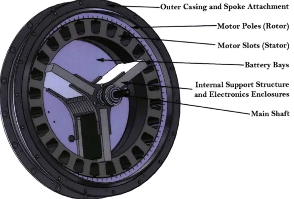
Outer Casing and Spoke Attachment Motor Poles (Rotor) Motor Slots (Stator) Battery Bays Internal Support Structure and Electronics Enclosures
Main Shaft
The thickness of the internal structure is dictated by the height of the batteries. Care was taken in the design of this structure to allow for battery connections while minimizing the axial width of the battery pack. The two cover plates on either side of the pack (Pictured but not labeled. see "Battery Bays") serve to secure the three beams to the central support structure that is attached to the shaft axially. These beams slide into the central support structure and are not bolted in place in any way. In the radial direction the beams are constrained between the stator and central support (notice the notch on the stator). The cover plates also provide axial mounting surfaces for the battery packs. Each plate is made from 1mm thick 6061 T6 aluminum.
As can be seen in Figure 2.5, the internal structure of the BEAU is relatively simple. Care was taken to make assembly and repair/troubleshooting an easy process by eliminating unnecessary bolts, screws, and mount points and instead taking advantage of already existing structures. For example, the battery packs rely on support from the stator support beams and the stator itself for positioning radial-tangentially. The center shaft mount (dark grey, centrally located supporting structure for the stator support beams in Figure 2.5), like the stator support beams, gets it axial positioning from the two cover plates that cap the internal structure.
In many previous figures where the main shaft has been pictured the reader may notice that it is hollow for a portion of its length on both sides. Previous instances of the BEAU concept have required opening the case or a hole in the outer casing in order to charge the batteries or reprogram the internal electronics. The BEAU attempts to solve this problem by making one side of the shaft a charging port and the other side a USB interface with the microprocessor.
The charging port uses the main shaft as ground and a large wire through the hole in the shaft as V+. The reason two wires were not run through the shaft is basically because they would not both fit, but using the main shaft as ground has the advantage of grounding the entire structure of the BEAU, which helps to prevent EM radiation leakage and accidental shocks. The charging pathways are required to be large because A123 cells are capable of charging at very high currents
- making it possible to fully charge the BEAU in 10 - 15 minutes. This arrangement also makes
the design of a "charging cap" that simply plugs into the end of the BEAU's shaft easily and safely. The USB interface on the opposite end of the shaft to the charging port allows for communication with the microprocessor through an Future Technology Devices International FT2232H dual UART
USB interface IC. The ability to directly communicate with the microprocessor without having to
remove the casing can be used to update the control code on the microprocessor during testing and control system verification. During normal use - as a product by non-technical user - the USB port can be used in combination with software on a computer in order to retrieve trip data and possibly change the assist ratio. Trip data includes data such as distance traveled, energy contributed by the rider, energy used by the motor, and velocity versus trip progress graphs.
2.4. AESTHETICS
Aesthetics, in the interest of this document, is defined as the industrial engineering side of the design of the BEAU. To many it is considered an art - a subjective process that results in subjective appearance. Because of this conception industrial design is much harder to quantify and evaluate
than product design, which is based in engineering and hard numbers3. Industrial design seeks to elicit a feeling from the viewer. This feeling is in the form of an idea or emotion that does not necessarily require expression in words. It is the goal of the designer to make the evocation of his work as universal as possible - walking the line of objective emotion.
The BEAU has a fair challenge in the aesthetics department because it is only a small part of a largely undefined overall look. That is, the bicycle to which the BEAU attaches is unknown. In order to maintain a consistent form language throughout, care must be taken to recognize and characterize the idea of the bike as a form of its own and make the lines on the BEAU's outer casing reflect that form.
The BEAU does not have a lot of room for changes to its form. It must be cylindrical in nature for rotational symmetry reasons - otherwise it would wobble instead of spin! The width of the casing at its attachment point to the bicycle is fairly well defined and must fall within the 120mm to 130mm range. Even the diameter of the casing is defined by the motor and the necessity to minimize spinning mass - this means that the outer diameter must be just larger than the outer diameter of the motor rotor.
So what can be changed? The BEAU casing transitions from 30mm in thickness to 121.69 mm in thickness from its outer edge to the shaft mount point. The profile of this transition is what can be changed. The profile could be made to be a spline, a smoothly varying curve throughout the radius of the casing; a tangential curve, angular surfaces whose transitions are smoothed by tangency curves; or an angular surface, flat surfaces with angular intersections and no curved transitions. Initially, one might perceive the bicycle as having the form language of curves. Its frame is generally made with cylindrical tubing, round wheels, and circular motion of the pedals and wheels. In fact this is not the case. If asked to draw a bicycle most would respond by drawing hard angular lines in triangular shapes with circles for wheels. The form of the bicycle is actually angular in nature. For this reason the BEAU is designed using angular features as can be seen most easily in Figure 2.1. The profile abruptly increases to allow room for the internal components, then slowly transitions to full width. The break between the transition serves to reduce the perceived diameter of the casing. Without this break the entire surface would look more like a featureless flat plate.
...or so the conception goes. The author would like to argue that industrial design is less subjective and product design is more subjective than perception suggests.
3.0.
THE MOTOR: MOVING THEBEAU
FORWARDThe BEAU uses a custom 800W peak, 24-pole, three-phase, frameless, brushless DC torque motor. In the electric bicycle world this type of motor is used occasionally with the best example of its use in the BionX electric bicycle conversion kit. This type of motor is available commercially, but limitations on budget and size options required the motor to be custom designed. This section will cover a small amount of the basics of motor design, the specific design of the BEAU's motor, and the BEAU motor fabrication process.
3.1. MOTOR DESIGN BASICS
Brushless motors differ from brushed motor in the fact that - as their name suggests - they do not have brushes. The brushes in brushed motors serve the purpose of controlling the commutation of the motor. That means that the brushes determine which coils on the motor get energized depending on the rotational orientation (0) of the motor. Brushless motors require electronic commutation. In general, both brushed and brushless motors are built the same way in terms of the arrangement of magnets and coils, which varies greatly depending on the purpose and requirements of the motor.
A motor is a magnet machine that uses electric current to produce kinetic or mechanical energy
through electromagnetic force. The electric motor was first invented by Michael Faraday in 1821. It consisted of a free-hanging wire that was hung like a pendulum in a pool of mercury. The center of the pool contained a magnet. When an electric current was run through the wire it rotated around the magnet. Faraday made a simple magnetic circuit in order to cause a physical rotation.
3.1.1. AIR GAP FLUx DENSITY
A magnetic circuit is made of one or more closed loop of magnetic flux. Magnetic circuit analysis
exploits the relationships between the equations that describe magnetism and magnetic flux and those that describe electricity and electrical circuits. Using these circuits we can develop ideas about how a motor works and use these ideas to aid in its design.
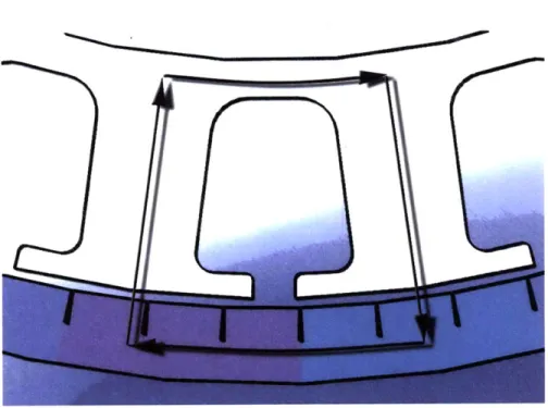
Figure 3.1 shows the flux path for one loop of the BEAU's motor. This loop repeats for every half-pole pair in the motor. For the BEAU's motor which has 24 poles this means that there are 24 half-pole loops. In order to transform this diagram of the flux path into something that mathematically and scientifically understood, we will use the theory of magnetic circuits. Through the path of flux there are resistances to and sources of flux. The air gap between the rotor and stator, for example, is a very large resistance to flux. The total flux crossing the air gap is the sum
Figure 3.1: A diagram of the flux path for one loop in the BEAU's motor.
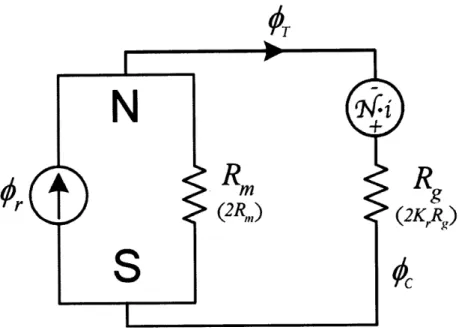
The magnetic circuit model shown in Figure 3.2 has two values for the reluctances of the rotor and stator. The first value ignores flux leakage between elements (such as leakage between the magnets that does not pass through the stator) and the second takes them into account. From Hanselman
[7] we can see that
Rm = m (3.1)
POIRAm
R9 = g (3.2)
90
Agwhere 1m is the motor length (depth), Mo is the vacuum permeability, MR is the recoil permeabilityl,
Am is the cross-sectional magnet area, g is the air gap distance, and Ag is the cross-sectional air
gap area. In order to account for flux leakage and reluctance variability in a simplified manner we
will use the constants K and Kr for flux leakage and reluctance variability respectively. This gives an air gap flux of
S = A. (3.3)
1 + KruRmAg
Combining Equations (3.1), (3.2), and (3.3) with the air gap flux density definition - Bg =
-gives a good estimation of the flux density of a motor based on elementary physical constants such
'Recoil permeability is an indication of a permanent magnet's ability to magnetize and demagnetize. In terms of the magnetic hysteresis loop, it is equal to d on a B-H plane for a given magnetic material[12].
A
R
R
r
(2R,n)
(2KRg)
Figure 3.2: A diagram of the magnetic circuit for the close loop flux path.
as the air gap and magnet length and cross-sectional area.
B = lKC B (3.4)
9 1 +KrAR
C, is equal to A, Pc is equal to , and Br is the flux density of the magnet. In terms of motor design, we can see that it is important to keep the air gap area equal to the magnet area. This can be accomplished by designing the heads of the stator to be roughly the size of the magnets per pole[1]. The air gap distance is the key value that can be changed to modify the resulting motor torque.
3.1.2. MOTOR TORQUE
The flux density across the air gap is the driving factor in motor motion; it represents the energy gradient between the rotor and stator. Together with N, r, and l, the flux density forms the motor
constant[13]. The resulting motor torque can be reasonably approximated with
r = (4NB91r)i, (3.5)
which is the torque produced by a single phase of a brushless motor2. N is the number of turns
per phase,
i
is the stator length (in the z direction, parallel to the motor's axis of rotation), and iis the current supplied to the coils. The parenthesis are to indicate the part of Equation (3.5) that
2
form the motor torque constant, or Kt. The constant '4' is determined through the drive technique (trapezoidal) and the number of passes through the EM field per loop (2)3.
3.2. MOTOR CALCULATIONS AND FEA ANALYSIS FOR THE BEAU
For calculations we will use:
* Ki = 1
* K, 1.1
P
pR 1.05
ePc
=3* B, 1.38 Teslas for N48 grade neodymium
* N 20 turns
* B9 = 0.996 Teslas
* is - 0.030 meters
* r = 0.115 meters * i 0 -> 20 amps
Calculations yield a flux density in the air gap (Bg) of 0.996 Teslas. Using this value we can see that the torque output per pole is Ktpoie = 0.275N. A Each phase has 8 poles ( 3phases 24poles) and twoantw phases are driven at one time in a WYE winding configuration, which gives us Ktmotor 4.40w. At peak torque the BEAU motor should be able to output roughly 85Nm.
3.2.1. FEA RESULTS - GRAPHS
In order to speed up the design process the motor for the BEAU was modeled using math only to the point of determining relative size, number of poles, winding requirements, and air gap. The rest of the design process was completed with the help of motor magnetic FEA software called MotorSolve. The software allows a motor to be evaluated accurately and quickly, providing feedback such as non-idealized torque curves, back EMF, magnetic saturation, and motor efficiency.
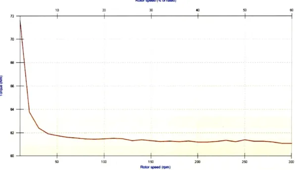
TOTAL TORQUE VERSUS ROTATIONAL VELOCITY
Figure 3.3 shows the torque output of the motor versus rotational speed. The FEA predictions and the theoretical predictions of the maximum torque in the magnetic circuit model are very close.
3For sinusoidal drive, this constant should be 3. Also this definition of torque is for approximation only and will
usually only be within a factor of two of the actual motor output torque. This accuracy is reasonable because it allows a motor designer to quickly ballpark a motor and the required drive techniques.
RO Sp0d(%ofradd)3
30
50 100 150 200 250
ROW Wd (rMM)
Figure 3.3: The total predicted torque output of the BEAU's motor.
POSdan (m~dnO do )
0 10 20 30 40 50 60
PO.0 (OC0 deg.")
Figure 3.4: The phase angle dependent cogging torque of the motor.
This result confirms the motor design and allows the design to move to manufacturing with the confidence that a working motor that meets the require specifications will result. Below are other
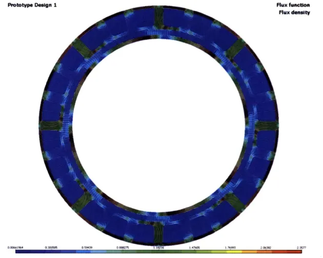
relevant outputs of the motor FEA software. Of interest is the plot of flux density over the surface of the motor.
COGGING TORQUE VERSUS PHASE ANGLE
We can see from figure 3.4 that the cogging torque is at maximum 7Nm. This is slightly high for the motor during "motor off" scenarios, but will be acceptable during motoring. In order to reduce this force the motor armature can be skewed. Skewing rotates the laminations axially as they are stacked, effectively smoothing out the transition between one pole and the next. Analysis with the MotorSolve software shows a decrease to 4.5Nm cogging torque with a 5 degree skewing angle[14].
BACK EMF VERSUS PHASE ANGLE
0 10 20 30 40 50 80 70 80 90
150 200 250 300 350
PosMn (oCke deoen)
Figure 3.5: The back electromotive force produced by the motor.
The back-EMF of the motor is used to gauge the rotor's electrical position. Back-EMF is also the reason why a motor has a maximum speed even while completely unloaded. Back-EMF generation
is a function of Wmotor, generally presented as ebemfWmotor where ebemf is the back-EMF constant
Rux densit flux d"Wety
0.136 4 0.30059639 05"N5 1.poIe 1A765 1.76995 20M2 2,357
Figure 3.6: An indication of the flux density distribution throughout the motor.
3.2.2. FEA RESULTS - PLOTS
FLUx DENSITY
The flux density plot helps determine areas of potential flux saturation. Flux saturation means that a conductor of flux has reached its maximum capacity. Like a wire conducting current, flux capacity is based on conductor physical dimensions and material. Unlike a wire conducting current, flux saturation does not result in fire.
TOTAL POWER Loss
Prototype Design 1
0 F 437 A igram o ta energ l d IZ o were 4and i ocu.
Figure 3.7: A diagram of the total energy loss during operation and where it occurs.
Total loes
4.0.
THE CONTROL APPROACH, THEORY AND IMPLEMENTATIONThis chapter will cover the basic theory behind the control of the BEAU from a control theory perspective with relevant detail given to the physical motor and vehicle dynamics and the electrical characteristics of the motor and control system. The control is implemented on a custom electronic circuit built for the BEAU. The circuit implements an Atmel based microcontroller and an Allegro Micro based MOSFET driver for power switching.
The BEAU relies on input from the rider to direct the motor's output power via current control. The rider input is in the form of a torque parameter that is measured using a flexure-based torque sensor, the design of which is described in Chapter 5. The torque input is combined with the wheel velocity to determine the total power that the user is providing to the system. This power can be equated into the electrical regime by dividing it by the voltage of the supply, yielding a current input for the motor modified by known motor inefficiencies.
4.1. CONTROL APPROACH
The BEAU control system is intended to be completely devoid of conscious input by the user. In other words, the user should not have to think about control strategies while riding a BEAU enabled bicycle. In order to accomplish this the method of determining the desired motor torque must be based on a parameter that can be measured without modifying the normal user interaction with a bicycle. It becomes obvious from this design goal that the best way to control the motor is to base its torque on the torque provided by the user during travel. There are various ways of accomplishing this:
1. Force sensors on the pedals: using force sensors on the pedals will give an indication of the
contact force between the riders feet and the pedals at any given time. This force can be translated into torque at the wheel by multiplying by the pedal radius, dividing by the first sprocket radius, and multiplying by the wheel sprocket (freewheel) radius. This sensor would need to be on a rotating part of the bicyclel
2. A torque sensor on the drive sprocket: This is one of the most common placements for torque sensors on bicycles. The torque sensor is located in the connection between the drive sprocket and the frame (the drive sprocket is connected directly to the pedals). This allows torque sensing without requiring the sensors to be rotating.
"'This sensor would need to be on a rotating part of the bicycle." is a nod to the fact that in most cases the processing electronics would be on a part of the bicycle that would not be rotating. This brings about several issues that necessitate the use of slip-rings or RF circuits to resolve.
3. A chain-based resonance measure of torque: Based on elementary kinematics theory, the
vibration frequency of the chain is an accurate measure of the tension on the chain. If this frequency is measured using inductive or capacitive sensing, the torque on the chain can be approximated. This is an academically interesting yet difficult to implement solution to measuring torque.
4. Strain-gauge based torque sensors in the motor casing: Because the motor casing only experi-ences the motor's torque at the outer edges of the casing, it is possible to place strain gauges on the casing between the freewheel connection and the wheel mount to measure the strain, and therefore torque, on the casing due to the rider input. This would require the sensors to be rotating.
5. Flexure based torque measurement: By placing a spring between the freewheel and the motor
casing, the torque can be directly sampled as a function of spring displacement. This has several advantages due to the fairly linear torque-displacement curve of a flexure under load. This would require that the sensor be rotating2.
4.1.1. TORQUE SENSOR SELECTION
A major design goal of the BEAU is that it be completely self-contained. Taking this into account,
it is obvious that all but the last two options in the above list are not applicable. Item 4 is a valid option, but the necessity of slip rings or RF devices in order to communicate the strain measurement to the internal non-rotating electronics make this option less preferable because RF is likely to be difficult due to interference with the motor RF emissions and slip rings are inherently noisy and large. Item 5, the flexure based torque measurement, is likely the best option for several reasons. Not only does it provide a clean torque estimate over the entire range of possible torque input from the user, is also provides a spring constant between the freewheel and the wheel, which acts to decrease the slope of the line on which the motor torque output needs to reside[4].
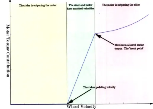
The graph in Figure 4.1 shows the toque contribution of the motor with reference to the wheel velocity given a fixed velocity input provided by the user. Keep in mind that this is not the total torque output of the motor, merely the effective torque output to the ground after factoring in the torque provided by the user to maintain the wheel at the fixed velocity input. Also, the graph represents the instantaneous state where the motor meets a specified torque requirement. After this point in time the wheel velocity will increase due to the motor's effective torque contribution
being non-zero, which will move the fixed velocity to a new point.
If the motor's torque is not high enough to reach the wheel velocity of the rider, then the motor will effectively drag on the user, the curve is effectively flat in this region, but in reality is has some small non-zero slope. At the point where the motor's torque is equal to the rider's input torque the motor begins to contribute to the system. This part of the curve is very steep, because a very small amount of torque increase from this point will lead to the motor outpacing the rider, causing the rider's drivetrain to freewheel, and effectively leading to the rider contributing zero torque to the system. The spring in the flexure helps to control this situation by providing a direct sensor link between position on this steep slope and motor torque.
2
The rr lprisg tetesr 0e ridr
-m
.... snowemaeior lovsm The look ieaFigure 4.1: From the motor's perspective, the torque construction must match the riders velocity while providing torque in a range that neither drags on the user nor overpowers the user. Unfortu-nately this zone (in green) has a very steep slope. The spring in the flexure helps to lessen the slope while also accurately instrumenting it in order to provide precise feedback to the control system.
4.1.2. SYSTEM DYNAMICS
The BEAU is meant to control the system that includes not just itself, and the rotational inertia of its casing and the input torque of the rider3, but also the unknown rotational inertia of the wheel, the linear inertia of the bicycle and its rider.
During periods of motoring, the motor will be controlled with a second-order proportional-differential position controller. The position in question is the displacement Ofz exure, which translates directly
to the error of Opedal - Owheel4. The control system will seek to make Opedal - 6wheel zero at all times. With reference to Figure 4.1 we can see that this will create a situation where the motor torque is always equal to the rider's input torque.
The BEAU will not always be motoring. During times when Opedal < Owheel but 6pedal > 0 (both 6
pedal and 6wheel are referenced from the bicycle shaft, which is rigidly attached to the bicycle
frame) the BEAU will be in "coast" mode. In this mode the motor will be electrically off, allowing
3
Keep in mind that this torque input is a kinematic input to the control system that is connected to the wheel through a spring. The control system must act in such a way as to keep this spring under minimum deflection.
4
There is interchangeability between Oheel and 9motor because the two are mechanical identical measurements.
Opedal is the measurement of the freewheel itself, which is not only connected to the motor via the spring flexure, but also is allowed to freewheel when 6pedal < 6wheel.
.. ...... ...
the bicycle to coast as a normal bicycle would. During times when Opedal < 0, (The rider is
pedaling backwards) the BEAU will enter regenerative braking mode, slowing the bicycle down proportionally to the speed at which the rider is pedaling backwards. This regenerative braking technique allows the normal physical breaks to function nominally. Figure 4.2 shows the overall topology of the BEAU's control system.
Figure 4.2: A diagram of the various states in which the BEAU can exist during operation. Note that the off and on states are triggered automatically and require no conscious user input.
4.2. CONTROL IMPLEMENTATION
Many of the standard control system techniques are very familiar. The BEAU does not use any out-of-the-ordinary control scheme. The BEAU implements a simple PD controller which transforms between 6-space and voltage space in the form of an adjustable resolution PWM output signal[2]. For the purposes of simulation the PWM constants can be removed in order for the controller to interact with the plant model more easily.
4.2.1. THE ELECTRICAL EQUATIONS
R
aL
a eaVa
R
Rb
L+
Lb
eb
N Vb Cc
+(a) Motor Coil Connection Method (b) Motor Equivalent Electrical Circuit
Figure 4.3: Diagrams of the motor electrical systems. The motor is wound with a WYE type winding as opposed to delta. The equivalent circuit used to calculated the plant model in the control systems tests.
The motor's design makes it a very large inductor. This inductance tends to oppose changes in current. The motor also generates a back-EMF voltage which is based on KE and Wm (the back-EMF constant and the angular motor velocity), and resists the flow of current with a resistance R[18]. Ignoring the three separate phases of the motor we can show that the voltage in terms of i
and wm is
di
V =L- + Ri + KEWm. (4.1)
dt
In order to get the phase specific solutions the number of pole pairs comes into play[5]. For a three-phase, thirty-two pole motor the number of pole pairs is 16. This number is multiplied by
Omotor
in order to get the electrical phase angle, or a = p0m. With the electrical phase angle knownwe can determine the voltages for each phase.
Va = iar + L
+
Ke m sin(a)dt dt
dib d~m 2,r
Vb = ibr+L +Ke sin(a+-3
dt dt 3
V = icr + L * + Ke m sin(a + -) (4.2)
For current, the same holds. i,, = itsin(a) 27r ib = itsin(a + 3-) 3 47r t,=itsil(O + -) 3
4.2.2. THE DYNAMIC EQUATIONS
V
Vb >
MO
V
(4.3)
Figure 4.4: A dynamic model of the BEAU in a simple form. All inertial terms can be lumped. Figure 4.4 shows a simplified representation of the motor and overall system's physical dynamics. The dynamic equations are slightly more difficult to simulate because the mass of the bicycle, rider, and wheel are not knowns (nor will the ever be), but these uncertainties can be addressed through the controller and are therefore not necessary to consider these varying parameters while developing the plant model because the range of the unknown's possible values are known.
rm
can be determined from physical parameters to berm = Ki = (Jm + J + r3(mB -| mr)) d2 motor Ks(pedal motor).
dt2 dt (pdl-Ooo) (4.4)
Combining Equations 4.2, 4.3, and 4.4 allows us to reach a plant model[20]. The plant is referred to as an equation in the s-domain that is a quotient of the output variables over the input variables for a given system, thereby simulating the physical response of a real system through the use of analysis. In implementation, the plant equations do not exist in the microcontroller.