AN ASSESSMENT OF THE AERODYNAMIC, THERMODYNAMIC, AND
MANUFACTURING ISSUES FOR THE DESIGN, DEVELOPMENT, AND
MICROFABRICATION OF A DEMONSTRATION MICRO ENGINE
by
Jonathan M. Protz
Bachelor of Science in Aeronautics and Astronautics, Massachusetts Institute of Technology, 1995 Master of Science in Aeronautics and Astronautics, Massachusetts Institute of Technology, 1997
Submitted to the Department of Aeronautics and Astronautics in partial fulfillment of the requirements for the degree of
Doctor of Philosophy
at the
Massachusetts Institute of Technology
September 2000
© Massachusetts Institute of Technology. All rights reserved.
Author
(
)
/
Department ot Aeronaatac&2L AstronauL1u August 14, 2000 Certified by JProfessor Alan H. Epstein R.C. Maclaurin Pr4 ssor of Aeronautics and Astronautics, Committee Chairman Certified by
Professor Jack L. Kerrebrock Professpr of Aeronautics and Astronautics, Emeritus Certified by
rofessor S. Mark Spearing Esther and Harold i Edgertpn Ass#iatePfq§spr of Aer$autics and Astronautics Certified by
Professor Martin A. Schmidt Minor A<Nisor, Professor of Electric l Engineerin and Computer Science Certified by
Professor Nesbitt W. Hagood Chairman, Department Graduate Committee
MASSACHUSETTSINSTITUTE OF TECHNOLOGY
AN ASSESSMENT OF THE AERODYNAMIC, THERMODYNAMIC, AND MANUFACTURING ISSUES FOR THE DESIGN, DEVELOPMENT, AND
MICROFABRICATION OF A DEMONSTRATION MICRO ENGINE
by
Jonathan M. Protz
Submitted to the Department of Aeronautics and Astronautics
on September 12, 2000, in partial fulfillment of the requirements for the degree of
Doctor of Philosophy
ABSTRACT
Silicon microfabrication is an established technology for the manufacture of integrated circuits and micro-electromechanical systems (MEMS) devices such as pressure transducers and accelerometers. Recent advances in silicon microfabrication technology allow the possibility of designing high-precision mechanical devices for power conversion. Micro gas turbine engines (microengines) are one particular application of this technology. These tiny jet engines have immediate application as propulsion systems for Micro UAVs Other envisioned applications include portable electrical power generation for commercial, consumer, and military uses A microengine-based power or propulsion system could offer more than 10x the performance of a battery of the same weight. This would make it an enabling technology for long-duration portable computers, high-power mobile phones, and other portable power applications. This thesis describes an assessment of the aerodynamic, thermodynamic, and manufacturing issues associated with the design, development, and microfabrication of an all-silicon demonstration microengine. The design goal is the simplest feasible engine that can demonstrate the micro gas turbine engine concept. This demo microengine integrates high-speed, low Reynold's number turbomachinery, high-speed micro gas bearings, a compact hydrogen combustor, and an innovative turbine cooling scheme into a quarter-sized turbojet engine with a target thrust of 10 grams. Due to the scale of the device and the nature of the microfabrication process, the engine components are tightly coupled and the design involved a number of system trades not normally encountered in conventional engines. This thesis addresses several of these key design trades and identifies thermo-structural design and manufacturing constraints as the two principal limitations on current microengine design. The thesis also discusses the fabrication development effort and results culminating in a micro turbocharger that has been tested to speeds of up to 30,000 RPM. Rotor imbalance was identified as the probable limit on current operation.
Recommendations for future work include development of advanced turbine cooling schemes to improve device efficiency and development improved fabrication capabilities to reduce rotor imbalance.
Thesis Supervisor: Professor Alan Epstein
ACKNOWLEDGEMENTS
This thesis would not have been possible without the support and encouragement of a great many people.
I would first like to thank my family: my parents for giving me the opportunity to attend MIT in the first place and for giving me their constant support throughout school, and my brother, Chris Protz, for his encouragement and good humor while I worked on my thesis.
I would like to thank my advisor, Prof. Alan Epstein, for offering me the opportunity to work on the microengine as the 'project engineer' in the first place. This program provided many more learning experiences and opportunities than a typical PhD program would and I am grateful. I would also like to thank the other members of my committee, Prof. Mark Spearing, Prof. Jack Kerrebrock, and Prof. Marty Schmidt for their support particularly as my defense date drew near. I would also like to thank Prof. Ian Waitz, Prof. Kenny Breuer and all of the other faculty members and research staff involved with the project for their invaluable advice and assistance.
The engine design is the product of a terrific team of students and researchers. Dr. Stu Jacobson helped with the overall design and offered extremely valuable assistance with the experiments. Kuo-Shen Chen, Wenjing Ye, Dr. Eugene Huang, Kevin Lohner, and Bruno Miller carried out all of the detailed structural design work. Dr. Stu Jacobson, Prof. Kenny Breuer, Dr. Fred Ehrich, DJ Orr, and Ed Piekos helped identify bearing concepts and performed all of the bearing analysis. Amit Mehra, Steve Lukachko, Dr. Chris Cadou, Chris Spadaccini, Jin-Wook Lee, and Sumita Pennathur researched combustion and developed a 'hot static structure' based on the demo engine design. Dr. Choon Tan, Dr. Stu Jacobson, Dr. Harold Youngren, and Dr. Yifong Gong, Greg Shirley, and Kashif Khan worked on the turbomachinery design and testing. Chunmei 'May' Liu analyzed the microengine dynamics. Maddie Close cross-sectioned and epoxied the dies. Todd Harrison took care of all packaging needs. Many other students and researchers contributed ideas and suggestions based on their work with related devices and I would like to thank them as well.
In particular, I would like to thank Adam London, Luc Frechette, and CC Lin for their overall design advice. I would also like to wish the best of luck to follow on team of microengine students including Nick Savoulides, Baudoin Philippon, Dongwon Choi, Hyung-Soo Moon, and Chee Wei Wong.
The turbocharger and demo engine would never have been built were it not for the efforts of an outstanding microfabrication team. Dr. Arturo Ayon, Dr. Xin Zhang, and Dr. Ravi Khanna gave strong advice, helped identify and solve a host of fabrication problems, and carried out much of the fabrication effort themselves. Tom Takacs and Dennis Ward did the heavy lifting and made outstanding observations that greatly accelerated a sometimes frustrating fabrication process. Together this team built all of the devices described in this thesis.
Jimmy Letendre, Victor Dubrowski, and Bill Ames constructed all of the testing apparatus and made all necessary emergency repairs to the test facility. Their efforts are greatly appreciated. Thanks to Diana Park who drew many fine demo engine illustrations, several of which are presented here. I would also like to thank Anne Maynard and Holly Anderson for always making sure my stipend money was available.
Working on a project of this unique stature and nature also provided me with the opportunity to participate in the MIT $50K Entrepreneurship Competition. This was a very rewarding experience and I wish to thank Luc, Adam, Amit, Lee, Joe, Nick, Jeff, Diego, Chee Wei, and all of my '99 and '00 $50K team members for their participation. I would also like to thank Heather Wilding, the '00 $50K lead organizer, for encouraging us to enter and Sachin, the '99 communications coordinator for getting us into Newsweek.
Thanks to all of the students and staff of the GTL for making this a fun and rewarding experience.
This work was supported in part by a National Defense Science and Engineering Fellowship from the DoD. It was also sponsored by the United States Army Research Office, Dr. R. Paur and Dr.
T. Doligalski, technical managers and by DARPA, Dr. R. Nowak, Dr. D. Fields and Dr. S.
CONTENTS
Acknowledgem ents...5 Contents ... 7 Lisgt of Figures ... 11 List of Tables ... 13 1 Introduction... 15 1.1 Background ... 151.2 Dem o Engine Research... 16
1.3 Objective and Approach... 17
1.4 Applications of Research... 18 1.5 Previous W ork... 19 1.6 Organization of Thesis... 23 1.7 References... 24 2 System Design ... 35 2.1 Introduction ... 35
2.2 Functional Requirem ents and Constraints... 37
2.2.1 Functional Requirem ents... 37
2.2.2 Program m atic Factors... 38
2.2.3 Physical Constraints ... 39
2.2.4 M anufacturing Constraints... 41
2.2.5 Testing Requirem ents... 42
2.3 Layout ... 43
2.3.1 Baseline Dem o Engine ... 43
2.3.2 Fabricated Devices ... 45
2.4 Cycle Analysis ... 47
2.4.1 Fundam entals...47
2.4.2 Ideal Cycle Analysis... 48
2.4.3 N on-Ideal Cycle Analysis... 49
2.4.4 Baseline Cycle...53
2.4.5 Cycle Analysis Trade Studies... 54
2.5 M echanical Design Trades... 61
2.5.1 Turbine Cooling... 61
2.5.2 Turbine Inlet Temperature... 64
2.7 References ... 65
3 Component Design ... 87
3.1 Com pressor, Turbine, and Rotating Structure... 88
3.1.1 Com pressor...88
3.1.2 Turbine ... 92
3.1.3 Spool Structure ... 93
3.1.4 Spool Therm al Design ... 96
3.2 Com bustor and Static Structure ... 96
3.3 Bearings and Secondary Flow ... 97
3.4 References...99
4 Fabrication ... 107
4.1 Fabrication and Design ... 108
4.1.1 M icrofabrication Technology ... 108
4.1.2 System s Im plications of M icrofabrication... 109
4.2 Turbocharger and Dem o Engine Fabrication ... 109
4.2.1 Inherited Fabrication Techniques ... 110
4.2.2 Process Challenges ... 111
4.2.3 Geom etry ... 112
4.2.4 Etches ... 113
4.2.5 Process Flow ... 113
4.3 Process Issues and Developm ent...115
4.3.1 W afer A lignm ent and Bonding... 115
4.3.2 Uniform ity ... 116
4.3.3 Rotor Retention ... 116
4.3.4 Nested M ask Etches... 118
4.3.5 Multiple End Point Etches and Aspect-Ratio Dependent Etching ... 119
4.3.6 Therm ally Isolated Structures... 120
4.3.7 Etch Uniform ity Control with Through Etches ... 121
4.3.8 Advanced Geom etries...122
4.4 Lessons Learned and Conclusion... 124
4.5 References ... 124
5 Experim ental Setup... 141
5.1 Packaging ... 141
5.1.1 Cold Packaging... 141
5.1.2 Hot Packaging ... 142
5.2 Gas Handling and Instrum entation System ... 143
5.3 Data Acquisition System ... 145
5.4 references ... 145
6 Experim ental results ... 153
6.1 Thrust Bearing Experim ents ... 153
6.3 Rotor Spin Tests... 158
6.4 Recom m endations for Future W ork... 162
6.5 References ... 163 7 Conclusion ... 167 7.1 Contributions... 167 7.2 Lessons Learned... 168 7.3 Redesign... 170 7.4 References ... 173
A P P E N D I X A M icro A ir V ehicle System Study ... 175
A .1 References ... 176
A P P E N D I X B Cycle A nalysis Spreadsheet ... 180
A P N D IX C Turbine Cooling M odel ... bPE 182 A P P E N D I X D Cross-Journal Tab Experim ents... 186
LIST OF FIGURES
Figure 1-1: Illustration of microengine concept... 31
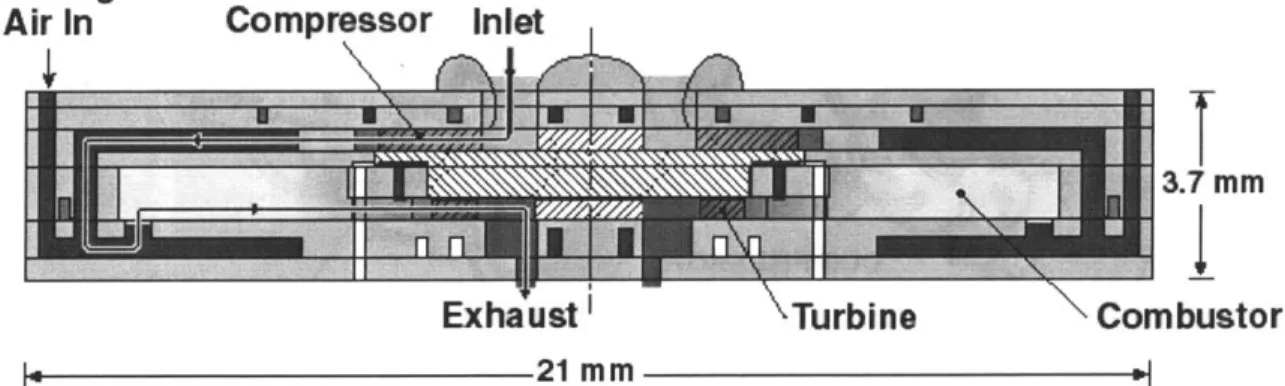
Figure 1-2: Cross-sectional illustration of demo engine showing flow path... 31
Figure 1-3: Three-dimensional illustration of demo engine cross section. ... 32
Figure 1-4: Three-dimensional illustration of demo engine cross section. ... 32
Figure 1-5: Illustration of demo engine fabrication concept... 33
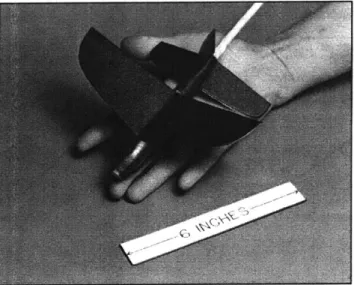
Figure 1-6: Photograph of MIT jet-propelled micro air vehicle mock-up. ... 33
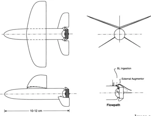
Figure 1-7: Three-view drawing of MIT jet propelled micro air vehicle... 34
Figure 1-8: Comparison of electric and jet micro air vehicles... 34
Figure 2-1: D em o engine sub-system s... 69
Figure 2-2: W afer stacking concept. ... 69
Figure 2-3: Demo engine development sequence. ... 70
Figure 2-4: Illustration of hot static structure... 71
Figure 2-5: Illustration of turbocharger showing separate gas paths. ... 71
Figure 2-6: Temperature-entropy diagram of the ideal Brayton cycle... 72
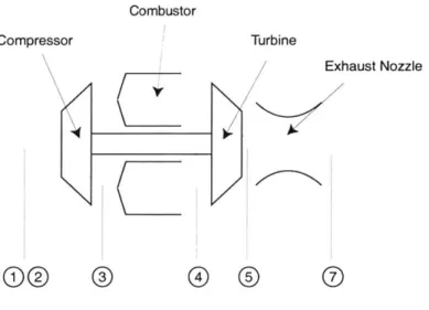
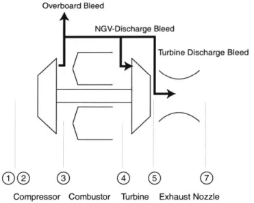
Figure 2-7: Schematic of a turbojet engine showing station numbers... ... 72
Figure 2-8: Increasing pressure ratio increases efficiency. ... 73
Figure 2-9: Increasing peak cycle temperature (Tt4) increases power output. ... 73
Figure 2-10: Impact of nonideal component behavior on the Brayton cycle...74
Figure 2-11: Principle types of compressor bleed in a single-stage turbojet. ... 74
Figure 2-12: Impact of turbomachinery performance on demo engine cycle...77
Figure 2-13: Low-pressure-ratio demo engine cycles... 77
Figure 2-14: Impact of non-ideal combustor behavior on demo engine cycle...78
Figure 2-15: Comparison of hydrogen and hydrocarbon combustion results...78
Figure 2-16: Impact of bleed on demo engine cycle. ... 79
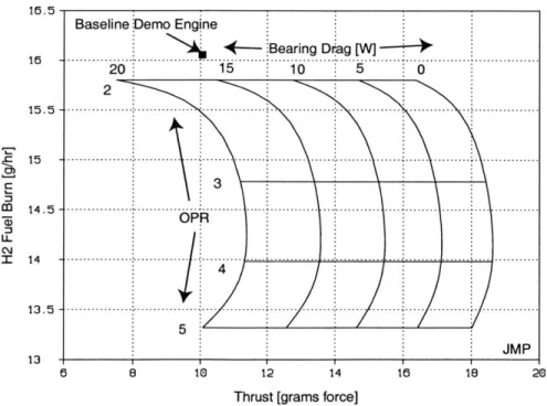
Figure 2-17: Impact of bearing drag on fixed massflow demo engine cycle...79
Figure 2-18: Demo engine performance as a function of speed... 80
Figure 2-19: Comparison of speed and cycle efficiency for various bearing drags...80
Figure 2-20: Break-even efficiency for the demo engine cycle...81
Figure 2-21: Illustration of conventional turbine cooling approaches. ... 82
Figure 2-22: Illustration of demo engine cooling mechanism ... 83
Figure 2-23: Varying thermal isolation by changing shaft area...83
Figure 2-24: Spool therm al behavior. ... 84
Figure 2-25: Engine performance as Tt4 is varied...85
Figure 3-1: Compressor and turbine blade geometry... 101
Figure 3-2: Compressor speedlines (100%) predicted by CFD. ... 102
Figure 3-3: Hot compressor behaves as 'pre heated' cycle... 103
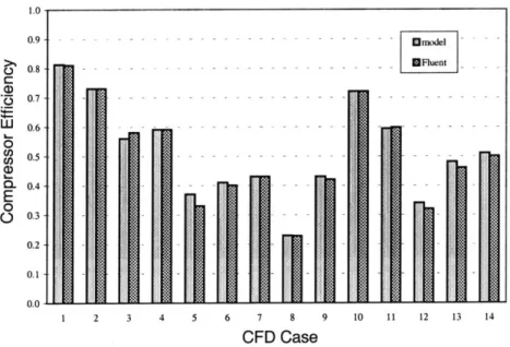
Figure 3-4: Comparison of efficiency model to CFD results... 103
Figure 3-5:Comparison of pressure ratio model to CFD results. ... 104
Figure 3-6: Comparison of mass flow model to CFD results... 104
Figure 3-7: Silicon strength versus tem perature. ... 105
Figure 4-1: Illustration of demo engine processing concept... 127
Figure 4-2: Important geometric features of the demo engine... 127
Figure 4-3: Exploded view of six-wafer demo engine/turbocharger die... 128
Figure 4-4: C ross-sectioned die. ... 128
Figure 4-5:Wafer-level image of turbocharger compressor wafer... 129
Figure 4-6:Die-level images of demo engine compressor wafers... 129
Figure 4-7: Wafer-level image of turbocharger turbines and combustors. ... 130
Figure 4-8: Bonded and die-sawed turbocharger die. ... 131
Figure 4-9: Cross-sectioned die showing rotor and static structure. ... 131
Figure 4-10: Demo engine fabrication process flow... 132
Figure 4-11: Schem es for rotor retention... 133
Figure 4-12:Cross-section of rotor hub showing thrust bearing gap ... oxide film... 134
Figure 4-13: Close-up image of compressor wafer showing ... bond pads ... hub...134
Figure 4-14: N ested m ask process. ... 135
Figure 4-15: Aspect-ratio dependent etching from Ayon et al. ... 136
Figure 4-16: Thermal isolation during cooling jacket etch... 137
Figure 4-17: 'Target m ount' handle wafers... 138
Figure 4-18: D eep journal bearings... 139
Figure 4-19: 400um blades on a demo engine compressor... 139
Figure 5-1: Metal cold package used for experiments. ... 147
Figure 5-2: Plexiglass cold package showing device and flow passages... 147
Figure 5-3: Hot package for long duration tests with combustion... 148
Figure 5-4: Schematic of gas handling system... 149
Figure 5-6: Photograph of gas handling system... 149
Figure 5-7: Illustration of fiber optic speed sensing system. ... 150
Figure 5-8: Schematic of data flow in data acquisition system... 151
Figure 6-1: Results of thrust bearing static flow tests... 164
Figure 6-2: Comparison of journal flow rate to analytical and CFD models... 165
Figure 6-3: Flow test through journal tap showing choked behavior... 165
LIST OF TABLES
T able 2-1: (intentionally
unused)...-Table 2-2: Comparison of GASTURB and Excel baseline cycle calculations. ... 75
Table 2-3: Baseline demo engine cycle and performance... 76
Table 2-4: Summ ary of cycle analysis results... 81
Table 2-5: Comparison of turbine operating environment... 82
Table 3-1: M aterial properties of silicon... 105
CHAPTER
1
INTRODUCTION
This chapter introduces the microengine concept and motivates the demo engine research effort.
1.1 BACKGROUND
In 1994, Epstein et al [1] proposed the concept of a centimeter-scale gas turbine engine manufactured from refractory ceramic materials using semiconductor fabrication techniques. Figure 1-1 illustrates this concept. This initial concept led to a comprehensive multidisciplinary research program at MIT that is focused on developing all of the fundamental technologies required to build such a device. These technologies include modeling and micro-fabrication of high-speed turbomachinery, high-speed gas bearings, compact combustion systems, high-power micro electrical motors and generators, temperature micro-scale packaging, high-performance structures, and advanced materials. These fundamental technologies have a broad range of applications including jet engines for propulsion, gas turbine engines for electrical power generation, motor-driven compressors for fluidic pumping and pressurization, micro-coolers for microchip cooling, and micro-rockets for small-scale space propulsion. The reader interested in learning more about the background of the research program and its practical applications can consult numerous articles in the academic [1,2,3,4] and popular [5,6,7] literature.
Even at a conventional scale, aircraft gas turbine engine design is among the most challenging of engineering design problems. A gas turbine engine involves many individual components that must operate together in a reliable manner at high rotational speeds and temperatures. This makes the design problem highly interdisciplinary. Fluid dynamic, thermodynamic, and structural concerns must be satisfied simultaneously for every mechanical component. Electrical
components such as the ignition system, starter motor, and electrical generator must operate efficiently and reliably at elevated temperatures. For flight applications, these components must be lightweight and extremely rugged. All of this must be done within the constraints of a realizable manufacturing process.
The microengine is a micro electro-mechanical system (MEMS) device. MEMS design is also highly interdisciplinary. A common MEMS device such as a simple pressure transducer can involve the design and analysis efforts of a structural engineer, packaging engineer, circuit designer, controls engineer, and fabrication engineer. Component design is tightly coupled in a MEMS device to simplify the fabrication process and reduce the device size. In many cases, portions of a MEMS device must serve dual roles, serving as both mechanical and electrical components. Small length scales make component thermal and mechanical isolation extremely
challenging.
Microengines represent the combination of both gas turbine engine and MEMS device design. As such, they span many fields of research including turbomachinery design, combustion, bearings and rotor dynamics, thermal and structural design, materials, electrical systems, and micro fabrication.
1.2 DEMo ENGINE RESEARCH
In 1997, MIT embarked on an effort to integrate fundamental microengine technologies into a working jet engine for demonstration purposes. This 'demo engine' is an all-silicon, hydrogen-fueled engine designed for simplicity and minimum technical risk. The fundamental research goal of the demo engine is to identify the critical integration issues associated with the microengine concept. These issues are driven by the integrated nature of the device and are separate from the research issues associated with each fundamental component technology. In addition, the demo engine will serve as the foundation for further development efforts aimed at small aircraft propulsion and portable electrical power generation.
The demo engine design is illustrated in Figures 1-2, and 1-3. The engine is a 2.1 cm square, 3.3 mm thick, all-silicon design with an 8 mm diameter compressor and a 6 mm diameter turbine spinning at 1.2 million RPM. The compressor and turbine blades are each designed to be 400 um
tall1. The compressor has a design pressure ratio of 1.8 and a design efficiency of 0.50. The combustor is designed for operation at 1600 K. The rotating turbomachinery is supported by a set of hydrostatic gas bearings that bleed 5% of the compressor flow. The engine's static and rotating structures are designed to operate at 1200 K and 950 K respectively.
The demo engine is designed to ingest 0.36 grams/sec of air, producing approximately 10 grams of thrust while consuming 16 grams/hour of hydrogen fuel. The engine has a predicted overall thermal efficiency of 2%.
The demo engine is fabricated from silicon using MEMS semiconductor microfabrication techniques. Each engine is assembled from six 10 cm diameter single-crystal silicon wafers that are etched to define features and then bonded together to form complete engines. Each wafer corresponds to one or more engine components. The bonded set of wafers is then cut into ten individual engines (called 'dies'). Figure 1-5 illustrates the fabrication concept.
1.3
OBJECTIVE AND APPROACHThe objective of the research presented here is to evaluate the feasibility of an all-silicon micro gas turbine engine. Three primary questions were considered:
(1) Is it possible to synthesize a closed-cycle demonstration engine design using the current state-of-the art design and analysis knowledge? To which parameters is the design most sensitive? What are the major integration issues?
(2) Can this design be fabricated using available state-of-the art microfabrication technology? What new fabrication capabilities, if any, would be required to achieve the design intent?
(3) Does the fabricated device deliver the intended performance? If not, what changes to the design or the fabrication are necessary to achieve the intended performance?
In order to answer these questions, the following steps were taken:
(1) An integrated, all-silicon, demonstration microengine was designed using the best available knowledge about micro-scale turbomachinery, bearings, combustion, structures, materials, and fabrication. This 'baseline' design was studied analytically to determine the impact of various design parameters on overall engine performance.
(2) A process flow to fabricate the engine was designed. This process was executed in MIT's Microsystem Technology Laboratory by MIT microfabrication experts. The design was
modified as necessary to allow fabrication with available tools and techniques.
(3) Initial experiments were conducted with the fabricated devices to determine their operating limits, compare these limits to analytical predictions, and isolate areas of the design that require additional effort.
These steps represent the beginning of a complete development process. Future work should focus on realizing the design intent with the fabrication and on testing such devices to determine how the component performance compares to theory.
1.4 APPLICATIONS OF RESEARCH
If successful, microengines would represent a quantum leap in compact power generation. Such devices would have major performance advantages over traditional compact power sources such as conventional gas turbine engines, diesel engines, fuel cells, and batteries.
In comparison to conventional engines, microengines offer more power per unit weight. Microengines benefit from the cube-square law. The weight of a gas turbine engine scales with its volume while its power output scales with the area of its inlet. Therefore, all else being equal, the power-to-weight ratio of the engine scales inversely with its size. Smaller engines have higher power-to-weight ratios. A microengine could conceptually offer 10-100 times the power to weight ratio of a conventionally sized gas turbine engine [1]. In addition, microengines are better suited to produce power at a small scale. With an appropriate integrated electrical generator, a centimeter-sized microengine could produce between 10 and 25 Watts of electrical power. This makes them well suited for portable electronics and portable computing
applications. At the same time, many microengines can be ganged together to provide power at the kilowatt level for distributed residential power or to power automobiles and similar vehicles.
Microengines also offer benefits over batteries. Unlike batteries, which are closed chemical systems, microengines are mechanical heat engines that generate power by converting the energy of a fuel burning with air into mechanical or electrical power. The energy released by burning a hydrocarbon fuel (-43.3 MJ/kg) is much larger than the energy released in the chemical reactions of a battery (-0.5 MJ/kg). In addition, the oxygen used in the reaction is supplied by the ambient air. Due to the small scale of microengines, the weight of a microengine electrical power system is dominated by the weight of the fuel. Even if a microengine had a thermal efficiency as low as
5%, it would still offer an energy density 5-25 times better than today's batteries [1].
Turbojet propulsion of micro air vehicles is one specific application for microengine devices. In conjunction with its microengine research effort, MIT has undertaken an effort to develop a six-inch wingspan, jet-propelled micro air vehicle, illustrated in Figures 1-6 and 1-7. This aircraft is designed for a flight speed of 30 m/sec and a range of 30 km. For micro flight applications, a turbojet microengine eliminates the batteries, power electronics, and motor inefficiencies of a traditional motor-driven propeller approach. As part of the present work, the author conducted a system study comparing the performance of a turbojet powered MAV to a battery-powered MAV. The study, detailed in Appendix A, showed that microengines offer a substantial performance improvement over batteries. This performance improvement is illustrated in Figure 1-8.
1.5 PREVIOUS WORK
As mentioned above, the development of the demo microengine is part of a comprehensive MIT effort covering all aspects of microengine technology. As such, the demo engine research is built on a large body of prior work in the field. The previous work fits into seven major areas of research, each addressing a specific aspect of microengine technology. These areas are: (1) systems integration, (2) thermal, structural, and material design, (3) combustion, (4) turbomachinery and fluid dynamics, (5) bearing design and rotor dynamics, (6) electrical machinery, and (7) fabrication. The previous work in each area is summarized below.
Systems Integration
Epstein initially proposed the microengine concept [1,2]. Groshenry studied the overall system [8]. This work laid the foundation for the demo engine, defining the initial geometry with its gas bearings, radial turbomachinery, and integrated combustor. This initial design was extended into a baseline gas turbine electrical generator concept presented in [1,2]. Esteve studied the role of the secondary flow system for this design [9]. Liu studied the dynamic response of microengines in general and found that fluid-thermo-structural coupling significantly altered the dynamics [10].
The baseline design of [1,2] was for a simple cycle, single-spool, single stage engine with a shrouded compressor and an integrated electrical generator/starter. The design had a nominal thickness of 3 mm, a die size of 10 mm, compressor and turbine diameters of 4 mm, and a journal bearing shaft diameter of approximately 900 um. There were eight wafers varying in thickness from 200 um to 800 um; one each for the fuel manifold, electrical generator/starter, compressor, gas bearing system, turbine, and exhaust nozzle. The combustor was made up of a combination of these wafers. The engine was designed to deliver a core mass flow of 0.16 g/sec at a pressure ratio of 4:1, with a compressor tip speed of 500 m/sec, a rotor speed of 2.4 million RPM, and a turbine inlet temperature of 1600K. The design called for silicon carbide as a structural material. The gas bearing system involves an eccentric hydrodynamic journal bearing along the spool shaft and hydrodynamic thrust bearings on the compressor and turbine disk backsides.
A number of researchers have considered other devices based on high-speed micro turbomachinery. These include motor-driven pumps [11,12] and micro rockets [13,38,15,16]. These devices laid some of the fabrication foundations for the demo engine design.
Thermal, Structural, and Materials Design
In order to achieve high pressure ratios and efficiencies, microengines must operate at the high temperatures (1400-2000 K gas and 800-1600 K structural), tip speeds (-500 m/sec), and stresses (100s of MPa) of conventional turbomachines. At the same time, the engine must use materials such as silicon that can be easily microfabricated. This requires precision structural analysis techniques and advanced materials. The thermal, structural, and fluidic analyses of a microengine are also tightly coupled, making the thermal design a challenging problem. Chen undertook a
comprehensive study of the material and structural issues of microengine design [17]. Chen especially focused on silicon as a material, performing much of the demo engine structural analysis [19,20]. Huang and Ye continued Chen's structural and thermal analysis, analyzing the design presented here [70,71]. Lohner studied silicon carbide and other advanced materials and showed that carbide could be incorporated into a silicon structure [22]. Miller extended Chen's work with silicon and Lohner's work with silicon carbide, developing the concept of a hybrid carbide/silicon structure [23]. Moon and Choi, are continuing work on a silicon carbide engine [24,25].
Combustion
Microengines are internal combustion engines requiring air ingestion, fuel injection, fuel-air mixing, and chemical reaction (combustion) of the fuel-air mixture. The combustion process is dominated by the need to mix and react the fuel within the time the flow is resident in the combustor. Because the chemical reaction times are independent of scale, this makes micro-scale combustion a challenging problem. Tzeng and Gauba first demonstrated pre-mixed combustion of hydrogen at micro-engine scales in a centimeter-scale steel and quartz combustor [26,27,28]. Mehra extended these results to a microfabricated silicon combustor [29,30]. Mehra also demonstrated hydrogen combustion in a microfabricated silicon 'hot static structure' that reflected the static structure of the demo engine [29,31,32,33]. Lee performed CFD studies of Mehra's rig [34]. Cadou and Spaddacinni are extending Mehra's results to hydrocarbon combustion with and without catalysts [35, 36].
Turbomachinery and Fluid Dynamics
Due to its small scale, microengine turbomachinery operates in laminar and transitional flow regimes with high heat transfer coefficients. The chord-based Reynolds number for the demo engine compressor is approximately 20,000. The heat transfer coefficients are in the range of 2000 W/m2
-K. In addition, microfabrication constraints lead to a very two-dimensional compressor geometry. Microengine turbomachinery was initially studied by Jacobson et al [37]. Mehra extended Jacobson's 2D CFD calculations to 3D [38,39]. Gong extended Mehra's compressor calculations to include the effects of heat transfer [40]. Phillipon is extending Mehra's turbine calculations to include high-temperature flows with heat transfer [41]. Jacobson,
Shirley, Khan, and Cadou studied micro turbomachinery in a dynamically scaled, conventionally sized, 'macro-rig' experimental facility [37,42,43,44].
Bearing Design and Rotor Dynamics
Microengines require low-friction bearings to support the rotating machinery against the rotor-dynamic loads experienced from running at millions of RPM. Orr, Piekos, Savoulides, Jacobson, Breuer, Ehrich, et al have studied gas bearings for microengines [45, 46, 47, 48, 49, 50]. These
bearings operate in physical regimes well outside established bearing theory, requiring the development of new experimental and analytical models for bearing behavior. Orr demonstrated both hydrostatic and hydrodynamic gas bearings in a dynamically-scaled 'macro bearing rig' and identified rotor imbalance as a critical issue [45]. Lin, Wong, Frechette, Jacobson, et al demonstrated high-speed operation of a microfabricated bearing test rig [51, 52, 53, 54].
Electrical Machinery
The demo engine research presented here focuses on a turbojet engine without electrical generating capability. Ultimately, however, a complete gas turbine electrical generator would require an integrated electrical generator. The generator could also be run as a motor to make a motor-driven pump. Nagle designed and tested a non-rotating electrostatic 'tethered motor' to demonstrated microfabricated electrical machinery [55]. Frechette [11] designed and tested a microfabricated motor-driven compressor based on the microfabricated bearing device of Lin [51]. Livermore [56] is currently developing a metal-process, microfabricated electrical generator based on the work of [11]. Koser, Allen, et al are developing a microfabricated electromagnetic motor [57]. In addition, much of the research on microengine fabrication technology has focused on the electrical motor and generator.
Fabrication
Microengines are MEMS devices built using semiconductor fabrication technology for precision fabrication and batch processing. A number of researchers including Ayon, Zhang, Khanna, Ghodssi, and others have undertaken extensive efforts to develop deep etching and bonding processes for microengine fabrication [58, 59, 60, 61, 62, 63, 64, 65, 66, 67]. This work includes high precision, 300 um deep etches for gas bearing fabrication, 200 um and 400 um deep etches for turbomachinery blading, and multiple-wafer bonding processes. Harrison [68] studied
glass-bead micro packing for fluidic interconnects. Mehra studied electrical interconnects [69]. Lin [51], Frechette [11], Mehra [29], London [13], and Nagle [55] also performed considerable process development for their respective microengine-related devices.
1.6
ORGANIZATION OF THESISThis chapter introduced the microengine concept and motivated the development and testing of a demonstration microengine. Subsequent chapters describe the demo engine design, development, and testing in detail.
Chapter Two presents the overall system design and layout of the demonstration engine. The chapter addresses issues of performance and mechanical design. It focuses on the impact of component behavior on overall system performance.
Chapter Three presents the individual component designs. The chapter summarizes the fundamental engineering issues associated with each component and addresses the impact of overall system requirements on individual component behavior.
Chapter Four describes the demo engine fabrication development effort. The chapter documents the fabrication process, identifies the important fabrication issues that are unique to the demo engine design, and summarizes the impact of fabrication capabilities on overall system design and performance.
Chapter Five describes the experimental setup used for testing the demo engine and related turbocharger devices.
Chapter Six describes the experimental results from tests that have been performed with the fabricated demo engine and turbocharger devices. The turbocharger devices reached a speed of 20,000 rpm and demonstrated behavior consistent with theoretical and empirical predictions. These experiments constitute the first successful operation of a two-wafer micro turbomachine.
Chapter Seven concludes the thesis by summarizing the demo engine research to date and identifying areas of focus for future research.
1.7 REFERENCES
[1] A. H. Epstein, Senturia, Anathasuresh, Ayon, Breuer, Chen, Ehrich, Esteve, Gauba, Ghodssi, Groshenry, Jacobson, Lang, Lin, Mehra, Mur Miranda, Nagle, Orr, Piekos, Schmidt, Shirley, Spearing, Tan, Tzeng, Waitz, "Power MEMS and Microengines," presented at IEEE Conference on Solid State Sensors and Actuators, Chicago, IL, June 1997.
[2] A. H. Epstein, Senturia, Al-Midani, Anathasuresh, Ayon, Breuer, Chen, Ehrich, Esteve, Frechette, Gauba, Ghodssi, Groshenry, Jacobson, Kerrebrock, Lang, Lin, London, Lopata, Mehra, Mur Miranda, Nagle, Orr, Piekos, Schmidt, Shirley, Spearing, Tan, Tzeng, Waitz,
"Micro-Heat Engines, Gas Turbines, and Rocket Engines", AIAA 97-1773, 28th AIAA Fluid
Dynamics Conference, 4th AIAA Shear Flow Control Conference, Snowmass Village, CO,
June 29-July 2, 1997.
[3] A. H. Epstein, S. A. Jacobson, J. M. Protz, L. G. Frechette, "Shirtbutton-Sized Gas Turbines: The Engineering Challenges of Micro High Speed Rotating Machinery," Plenary Lecture, 8' International Symposium on Transport Phenomena and Dynamics of Rotating Machinery (ISROMAC-8), Honolulu, HI, March 2000.
[4] A. H. Epstein, S. A. Jacobson, J. M. Protz, C. Livermore, J. Lang, M. A. Schmidt, "Shirtbutton-Sized, Micromachined, Gas Turbine Generators," presented at 39* Power Sources Conference, Cherry Hill, NJ, June 2000.
[5] A. H. Epstein, "The Inevitability of Small," Aerospace America, March 2000, pp. 30-37
[6] A. H. Epstein and S. D. Senturia, "Macro Power from Micro Machinery," Science, p. 1211, Vol. 276, 23 May 1997
[7] S. Ashley, "Turbines on a Dime," Mechanical Engineering, pp. 78-8 1, October 1997.
[8] C. Groshenry, "Preliminary Design Study of a Micro-Gas Turbine Engine." MS Thesis, MIT, Department of Aeronautics and Astronautics, 1995.
[9] E. Esteve, "Secondary Flow System Modeling," Technical Report, MIT GTL, 1996. [10] C. Liu, MS Thesis, MIT, Department of Aeronautics and Astronautics, 2000.
[11] L. Frechette, Development of a Silicon Microfabricated Motor-Driven Compressor, PhD Thesis, MIT, Department of Aeronautics and Astronautics, 2000
[12] L. G. Frechette, S. A. Jacobson, K. S. Breuer, F. F. Ehrich, R. Ghodssi, R. Khanna, C. W. Wong, X. Zhang, M. A. Schmidt, A. H. Epstein, "Demonstration of a Microfabricated High-Speed Turbine Supported on Gas Bearings," presented at Solid-State Sensor and Actuator
Workshop, Hilton Head Island, SC, June 2000.
[13] A. P. London, Development and Test of a Microfabricated Bi-Propellant Rocket Engine, PhD Thesis, MIT, Department of Aeronautics and Astronautics, 2000.
[14] A. P. London, "A Systems Study of Propulsion Technologies for Orbit and Attitude Control of Microspacecraft," MS Thesis, MIT, Department of Aeronautics and Astronautics, 1996.
[15] R. L. Bayt, Analysis, Fabrication, and Testing of a MEMS-Based Micropropulsion System,
PhD Thesis, MIT, Department of Aeronautics and Astronautics, 1999.
[16] C. S. Protz, "Systems Analysis of a Microfabricated Storable Bipropellant Rocket Engine," MS Thesis, MIT, Department of Aeronautics and Astronautics, 2000.
[17] K. S. Chen, Materials Characterization and Structural Design of Ceramic Micro Turbomachinery, PhD Thesis, MIT, Department of Aeronautics and Astronautics, 1999. [18] S. M. Spearing, K. S. Chen, "Micro-Gas Turbine Engine Materials and Structures",
presented at 21' Annual Cocoa Beach Conference and Exposition on Composite, Advanced Ceramics, Materials and Structures, January 1997.
[19] K-S Chen, A. A. Ayon, K. L. Lohner, M. A. Kepets, T. K. Melconian, and S. M. Spearing, "Dependence of Silicon Fracture Strength and Surface Morphology on Deep Reactive Ion Etching Parameters", presented at the MRS fall Meeting, Boston, MA, December 1998. [20] K-S Chen, A. Ayon, and S. M. Spearing, "Silicon Strength Testing for Mesoscale Structural
Applications", MRS Proceedings, Vol. 518, 1998, pp. 123-130.
[21] K-S Chen, A. Ayon, and S. M. Spearing, "Controlling and Testing the Fracture Strength of Silicon at the Mesoscale", Journal of the American Ceramic Society, 1999.
[22] K. A. Lohner, "Microfabricated Refractory Ceramic Structured for Micro Turbomachinery," MS Thesis, MIT, Department of Aeronautics and Astronautics, 1999.
[23] B. Miller, "Hybrid Silicon/Silicon Carbide Microstructures and Silicon Bond Strength Tests for the MIT Micorengine," MS Thesis, MIT, Department of Aeronautics and Astronautics,
[24] H. S. Moon, Personal Communication, MIT GTL, 2000, To be published in MIT PhD thesis
[25] D. Choi, Personal Communication, MIT GTL, 2000, To be published in MIT PhD thesis [26] Y-S Tzeng, "An Investigation of Microcombustion Thermal Phenomena," MS Thesis, MIT,
Department of Aeronautics and Astronautics, 1997.
[27] I. A. Waitz, G. Gauba, Y-S Tzeng, "Combustion for Micro-Gas Turbine Engines," ASME J. of Fluid Eng., Vol. 120, March, 1998.
[28] I. A. Waitz, G. Gauba, and Y-S Tzeng, "Combustors for Micro-Gas Turbine Engines," Proc. of the International Mechanical Engineering Congress and Exposition, November 1996. [29] A. Mehra, Development of a High Power Density Combustion System for a Silicon Micro
Gas Turbine Engine, PhD thesis, MIT, Department of Aeronautics and Astronautics, 2000. [30] Mehra and I. A. Waitz, "Development of a Hydrogen Combustor for a Microfabricated Gas
Turbine Engine", Solid-State Sensor and Actuator Workshop, Hilton Head Island, SC, June 1998.
[31] A. Mehra, I. A. Waitz, and M. A. Schmidt, "Combustion Tests in the Static Structure of a 6-Wafer Micro Gas Turbine Engine," 1999 Solid State Sensor and Actuator Workshop, June
2-4,1999.
[32] A. Mehra, A. A. Ayon, I. A. Waitz, and M. A. Schmidt, "Microfabrication of High Temperature Silicon Devices Using Wafer Bonding and Deep Reactive Ion Etching",
IEEE/ASME Journal of Microelectromechanical Systems, Vol. 8, No. 2, June 1999, pp.
152-160.
[33] Mehra, X. Zhang, A. A. Ayon, I. A. Waitz, M. A. Schmidt and A. H. Epstein, "A 6-Wafer Combuston System for a Silicon Micro gas Turbine Engine," submitted to the Journal of
Micro Electro Mechanical Systems.
[34] J-W. Lee, Personal Communication, MIT GTL, 2000, To be published in MIT MS thesis
[35] C. M. Spadaccini, Personal Communication, MIT GTL, 2000, To be published in MIT PhD
thesis
[37] S. A. Jacobson, "Aerothermal Challenges in the Design of a Microfabricated Gas Turbine Engine", AIAA 98-2545, 29th AIAA Fluid Dynamics Conference, Albuquerque, NM, June 1998.
[38] A. Mehra, "Computational Investigation and Design of Low Reynolds Number Micro-Turbomachinery," MS Thesis, MIT, Department of Aeronautics and Astronautics, 1997. [39] A. Mehra, S. A. Jacobson, C. S. Tan, and A. H. Epstein, "Aerodynamic Design
Considerations for the Turbomachinery of a Micro Gas Turbine Engine", presented at the 2 5th
National and l't International Conference on Fluid Mechanics and Power, New Delhi, India, December 1998.
[40] Y-F Gong, Personal Communication, MIT GTL, 2000.
[41] Baudoin Phillippon, Personal Communication, MIT GTL, 2000, To be published in MIT MS
thesis.
[42] G. Shirley, "An Experimental Investigation of a Low Reynolds Number, High Mach Number Centrifugal Compressor," MS Thesis, MIT, Department of Aeronautics and Astronautics,
1998.
[43] K. Khan, Personal Communication, MIT GTL, 2000. To be published in MIT PhD thesis [44] C. Cadou, Personal Communication, MIT GTL, 2000.
[45] D. J. Off, Macro-Scale Investigation of High Speed Gas Bearings for MEMS Devices.
PhD thesis, MIT, Department of Aeronautics and Astronautics, February 2000.
[46] E. S. Piekos, Numerical Simulation of Gas-Lubricated Journal Bearings for Microfabricated
Machines. PhD thesis, MIT, Department of Aeronautics and Astronautics, February 2000.
[47] E. S. Piekos, D. J. Orr, S. A. Jacobson, F. F. Ehrich, and K. S. Breuer, "Design and Analysis
of Microfabricated High Speed Gas Journal Bearings," AIAA Paper 97-1966, 28th AIAA
Fluid Dynamics Conference, Snowmass Village, CO, June 29-July 2, 1997.
[48] E. S. Piekos and K. S. Breuer. "Pseudospectral Orbit Simulation of Non-Ideal Gas-Lubricated Journal Bearings for Microfabricated Turbomachines," Paper No. 98-Trib-48, presented at the Tribology Division of The Americal Society of Mechanical Engineers for presentation at the Joint ASME/STLE Tribology Conference, Toronto, Canada, October
[49] D. J. Off, and S. A. Jacobson, "High Order Galerkin Models for Gas Bearings," submitted to
the Proceedings of the ASMEISTLE Tribology Conference, paper ASME/2000-TRIB-131,
Seattle, WA, October 2000.
[50] N. Savoulides, "Low Order Models for Hybrid Gas Bearings," MS thesis, MIT,
Department of Aeronautics and Astronautics, February 2000.
[51] C. C. Lin, Development of a Microfabricated Turbine-Driven Air Bearing Rig.
PhD thesis, MIT, Department of Mechanical Engineering, 1999.
[52] C. C. Lin, R. Ghodssi, A. A. Ayon, D. Z. Chen, S. A. Jacobson, K. S. Breuer, A. H. Epstein
and M. A. Schmidt, "Fabrication and Characterization of a Micro Turbine/Bearing Rig",
presented at MEMS '99, January 1999, Orlando, FL.
[53] Frechette, L.G, Jacobson, S.A., Breuer, K.S., Ehrich, F.F., Ghodssi, R., Khanna, R., Wong, C.W., Zhang, X., Schmidt, M.A. and Epstein, A.H., "Demonstration of a Microfabricated High-Speed Turbine Supported on Gas Bearings," presented at Solid-State Sensor and Actuator Workshop, Hilton Head Island, SC, June 2000.
[54] C. Wong, Personal Communication, MIT GTL, 2000. To be published in MIT MS thesis
[55] S. Nagle, Personal Communication, MIT GTL, 2000, To be published in MIT PhD thesis. [56] C. Livermore, Personal Communication, MIT GTL, 2000.
[57] H. Koser, Personal Communication, MIT GTL, 2000. To be published in MIT thesis.
[58] A. A. Ay6n, Lin, C.C., Braff, R., Bayt, R., Sawin, H.H. and Schmidt, M., "Etching Characteristics and Profile Control in a Time Multiplexed Inductively Coupled Plasma Etcher," 1998 Solid State Sensors and Actuator Workshop, Hilton Head, SC, June 1998. [59] A. A. Ay6n, Ishihara, K., Braff, R., Sawin, H.H. and Schmidt, M., "Deep Reactive Ion
Etching of Silicon," Invited Presentation at Materials Research Society Fall Meeting, Boston,
MA, November 30-December 4, 1998.
[60] Mirza, A.R. and Ay6n, A.A., "Silicon Wafer Bonding: Key to MEMS High-Volume
[61] A. A. Ayon, Ishihara, K,. Braff, R.A., Sawin, H.H., Schmidt, M.A., "Microfabrication and Testing of Suspended Structures Compatible with Silicon-on-Insulator Technology", submitted to the Journal of Vacuum Science and Technology, February 1999.
[62] Ay6n, A.A., Epstein, A.H., Frechette, L., Nagle, S. and Schmidt, M. A., "Tailoring and Controlling Etch Directionality in a Deep Reactive Ion Etching Tool," submitted to Transducers'99, Sendai, Japan, June 1999.
[63] A. A. Ay6n, Chen, D.-Z., Braff, R. A., Khana, R., Sawin, H. H., Schmidt, M. A., "A novel Integrated Process Using Fluorocarbon Films Deposited with a Deep Reactive Ion Etching (DRIE) Tool," Fall Meeting of the Materials Research Society, Boston, MA , November 29
-December 3, 1999.
[64] A. A. Ay6n, Braff, R.A., Bayt, R., Sawin, H.H., Schmidt, M.A., "Influence of Coil Power in the Etching Characteristics in a High Density Plasma Etcher," Journal of the Electrochemical
Society, Vol. 146, No. 7, 1999.
[65] A. A. Ay6n, X. Zhang and R. Khanna, "Ultra Deep Anisotropic Silicon Trenches Using
Deep Reactive Ion Etching (DRIE)," 2000 Solid State Sensors and Actuator Workshop, Hilton Head, SC, June 2000.
[66] A. A. Ayon, J. Protz, R. Khanna, X. Zhang and A. Epstein, "Application of Deep Silicon Etching and Wafer Bonding in the MicroManufacturing of Turbochargers and Micro-Air-Vehicles," 47th International Symposium of the American Vacuum Society, Boston, MA, October, 2000.
[67] X. Zhang, K.-S. Chen, R. Ghodssi, A. A. Ay6n and S. M. Spearing, "Residual Stress Characterization of Thick PECVD TEOS Film for Power MEMS Applications," presented at 2000 Solid State Sensors and Actuator Workshop, Hilton Head, SC, June 2000.
[68] T. Harrison, MS Thesis, MIT, Department of Aeronautics and Astronautics, 2000.
[69] A. Mehra, X. Zhang, A. A. Ayon, I. A. Waitz and M. A. Schmidt, "A Through-Wafer Electrical Interconnect for Multi-Level MEMS Sevices," submitted to the Journal of Vaccum
Science and Technology.
[70] E. Huang, "Thermal Design Trade Studies for A Silicon Turbojet Engine", MIT GTL Initial Report, October 1998.
Weighth Pat Count Diamtr.
conventianal,
a&tarbin
e iLGt I IG, GG 112 in,. Miere Engint [(poten tial) 2D grame 2 1/2 in. [et
ential ) 5D W 175 W-hr 3G a 35GG1 W-hzlka 5G W IDOG a175 Whr / P17re Cuntey b. Prit
Figure 1-1: Illustration of microengine concept.
Starting
Air In
Compressor
Inlet
3.7 mm
Exhaust
Turbine
Combustor
I. 21
mm
&|
Figure 1-2: Cross-sectional illustration of demo engine showing flow path.
Tower
Energy weight
Volume
Figure 1-3: Three-dimensional illustration of demo engine cross section.
OUTER CASING
, COMPRESSOR
ISOLATED COMBUSTOR
LOOKING AFT
LOOKING FORWARD
Forward Cap \
A3
Forward Thrust Bearing i 3
2 4 6
Compressor 20 8 1
Turbine
-Aft Thrust Bearing
Aft Cap
Figure 1-5: Illustration of demo engine fabrication concept.
Image courtesy M Drela
L Ingestion Extemnal Augmentor
Flowpath
10-12 cm
Image courtesy M Drela
Figure 1-7: Three-view drawing of MIT jet propelled micro air vehicle.
Range [km] 20 , 4,0 6,0 0 - 40 30 0 0 0 5% 20 0 0L 60 60 2'o 40 Endurance [min] Range [km] 25 50 75 100 10 2O 3 40 50 60 Endurance [min]
Figure 1-8: Comparison of electric and jet micro air vehicles.
40. o 30. a-cc 0 5 20. 0 0 3~10 a.0. Flight Turbojet 15 m/s (Isp = 1065) Propeller w/ Ideal LTC Battery (350 J/g, 250 mw/g) Propeller w/ Li Recharg. (175 J/g) Demo Turbojet Engine (Isp = 725) 0 Flight Turbojet 30 m/s (Isp = 1065)
Demo Turbojet Engine (Isp = 725) Propeller w/ Ideal LTC Battery (350 J/g) Li Recharg 125 70 )
CHAPTER
2
SYSTEM DESIGN
This chapter describes the overall system-level design of the demo micro engine, including definition of the functional requirements, cycle analysis, layout and preliminary design, and key trades. The primary goal of this chapter is to identify the fundamental engineering issues associated with the systems integration of a micro gas turbine engine by identifying and quantifying the critical tradeoffs encountered during design. The secondary goals of this chapter are to describe the global layout of the demo micro engine and to document the reasoning process
behind the design.
This chapter presumes a fundamental knowledge of gas turbine engines and of MEMS technology. References [1,2,3] provide additional background on thermodynamics and gas turbine engine design. Reference [4] provides background on MEMS technology.
2.1 INTRODUCTION
As described in Chapter 1, Introduction, the demo engine is a 2.lcm x 2.1 cm x 3.77 mm turbojet engine manufactured from single-crystal silicon using MEMS microfabrication techniques. The engine is designed for an air flow of 0.36 grams/sec and a hydrogen fuel bum of 16 g/hr, giving a thrust of 10 grams. The predicted thermal efficiency is 2%. As illustrated in Figure 2-1, the engine consists of three primary subsystems: high speed rotating turbomachinery, a combustor, and a gas-bearing system.
The turbomachinery is on a single, shaft-less rotor at the core of the engine. It is surrounded by an annular combustor and static structure. Gas bearings separate the rotor from the static structure. The advantages of the shaft-less arrangement are ease of fabrication versus a shafted design and a reduced wafer count. The disadvantage is a larger overall engine diameter due to the 'flat' combustor shape. As described below, the shaft-less design also plays a key role in the demo engine's turbine cooling scheme.
The demo engine rotor has no shaft and the turbine and compressor disks are bonded directly to each other. The compressor diameter is 8 mm. The turbine radius is 6 mm. Design blade height for both the turbine and the compressor is 400 um. As described in Chapter 4, Fabrication, the fabricated devices had 225 um tall (span) blades. Tip clearances are 20 um for both turbine and compressor. The spool is designed to rotate at a speed of 1.2 million RPM giving a compressor tip speed of 500 m/sec and a turbine tip speed of 375 m/sec. At this design speed, the compressor should produce an adiabatic pressure ratio of approximately 3.0. Turbine cooling is accomplished by conducting heat from the turbine structure into the compressor flow through the spool. The heating reduces the compressor pressure ratio. The turbine is smaller than the compressor to minimize heat transfer into the turbine. The spool is designed for a structural temperature of 950 K, a heat transfer of 50W, and a consequent compressor pressure ratio of 1.80.
The rotor is supported by a hydrostatic gas bearing system. The baseline design calls for internal pressurization. However, as currently fabricated, the bearings are externally pressurized. A 15 um wide gap at the outer edge of the turbine disk serves as the journal bearing for the engine. This gap is pressurized from a plenum that sits between the turbine static structure and the portion of the compressor disk that extends beyond the turbine. The forward and aft thrust bearings are formed from gaps that sit above 2 mm diameter hubs at the center of the rotor. Each bearing consists of a 3.5 um tall gap pressurized by twenty 11 um diameter, 100 um deep restrictor nozzles located at a radius of 0.75 mm.
An annular combustor surrounds the turbine. The hot section of the combustor is thermally isolated from the rest of the static structure by a 'cooling jacket' that wraps around from the compressor discharge to the backside of the combustor. This reduces heat loss to the outside environment and reduces the exterior temperature of the engine. The flow enters the combustor from the bottom through an array of rectangular inlet ports that hold the flame. Fuel is injected
into the flow through a circular array of injectors just downstream of the compressor. The engine is started by an external air supply that injects flow directly into the combustor.
The demo engine is a MEMS device that is built by bonding together individually patterned silicon wafers to form a final multi-level stack. Figure 2-2 illustrates the wafer-stacking concept. Each wafer in the stack represents a 'level' of the engine structure. Each level has one or more major engine components. The individual components are formed by etching the silicon to extrude two-dimensional geometries into prismatic three-dimensional structures. The details of etching are covered in Chapter 4, Fabrication.
The remainder of this chapter describes the system design of the demo engine in more detail.
2.2 FUNCTIONAL REQUIREMENTS AND CONSTRAINTS
Like the design of any machine, the design of a microengine is an open-ended problem representing an intricate trade-off between many conflicting constraints. Any number of designs may result in an operational system that satisfies all of the constraints while still meeting the functional requirements. The demo engine design was driven by the functional requirements and by the constraints imposed by programmatic need, those imposed by the physics of the device, and those imposed by manufacturing capabilities. The following sections describe these requirements and constraints.
2.2.1 FUNCTIONAL REQUIREMENTS
At the time of design, there were no imposed external functional requirements for the MIT demo engine or its descendents. There were no specific applications and, hence, no specific requirements for thrust, power output, size, or weight. The principle functional requirement of
the demo engine is to demonstrate integration of the microengine component technologies into a complete system.
Although integration is the only functional requirement of the demo engine, descendent engines should demonstrate a level of performance that plainly exceeds the performance of other compact
sources of power such as batteries and fuel cells. Toward these ends, the following set of general design goals were used for the demo engine:
(1) A design thrust of approximately lOg (equivalent to 10-20 watts of mechanical power). (2) An engine life of tens of minutes or longer.
(3) A design with a minimum number of unproven process steps. (4) Design for future growth potential:
- Addition of an electrical generator (electrical power output) - Hydrocarbon combustion (liquid fuels)
- Recuperation (improved thermal efficiency)
Given the considerable uncertainty associated with individual component performance, the engine was designed to produce as much power as feasible. This led to an engine that was as large as possible while still being deemed to satisfy the constraints of microfabrication. A larger engine leads to a higher mass flow through the engine and more efficient turbomachinery (higher Reynold's number). Both factors lead to higher power output.
2.2.2 PROGRAMMATIC FACTORS
The design of the demo engine is driven in many ways by the needs and constraints of the overall MIT microengine program. Many of the concepts and technologies that were part of the overall program were developed with a demonstration engine in mind. An initial engine concept led to a number of simpler 'test bed' devices that were built to demonstrate critical technologies. Lessons from completed devices were incorporated into the demo engine design.
The demo engine development was strongly influenced by the fact that much of the fundamental microengine research occurred concurrently with the demo engine design. Scheduling constraints place a high premium on evolving the engine out of existing, proven technology as much as possible rather than relying on the development of new and untested ideas. Resource constraints limit the number of design ideas that can be analyzed and implemented. In many cases, the demo engine is designed around what is practically feasible or even proven rather than what is theoretically optimal. This is why, for example, the demo engine uses a "plain" circular journal
bearing and an integral combustor. At the time of design, both concepts had already been used for other microengine development devices [5, 6, 7]. The following concepts used in the demo engine design were chosen for programmatic reasons:
(1) Gas bearings. Gas bearings are an outgrowth of MIT's micro bearing rig.
(2) Integral Combustor. An integral combustor is an outgrowth of MIT's micro combustor. (3) All-silicon construction. Currently, MIT can only fabricate with silicon.
(4) Single stage, single spool turbomachinery. This simplifies the device. (5) Hydrogen fuel. Hydrogen has the broadest flammability margins. (6) A simple Brayton thermodynamic cycle. This simplifies the device.
2.2.3 PHYSICAL CONSTRAINTS
The design is also constrained by the physics of the chemical, mechanical, and fluid-dynamic processes inherent in a gas turbine engine. The fundamental physical mechanisms that constrain the design are described here.
Combustor chemical reactions
The chemical processes within the combustor occur over a finite time period. If these reactions are to be constrained to occur within the combustion chamber, they must go to completion within the residence time of the flow in the combustor. This residence time is proportional to the combustor volume and inversely proportional to the engine volumetric flow rate. Thus, there is a minimum combustor volume that is set by the engine volumetric flow rate and the residence time required for the fuel-air reaction to complete. Increasing the pressure of the air increases the density and, therefore, increases the residence time for a fixed volume. Increasing the reaction temperature decreases the density but accelerates the reaction rate. Mehra demonstrated complete hydrogen and hydrocarbon combustion with residence times of 0.5 msec and 1.5 msec respectively [7].
Bearing stability
The engine's spool has a design speed of 1.2 million RPM. Unless the rotor can be accelerated quickly through unstable operating regions, the journal bearing must allow stable operation of the