HAL Id: hal-00077840
https://hal.archives-ouvertes.fr/hal-00077840
Submitted on 2 Jun 2006
HAL is a multi-disciplinary open access
archive for the deposit and dissemination of
sci-entific research documents, whether they are
pub-lished or not. The documents may come from
teaching and research institutions in France or
abroad, or from public or private research centers.
L’archive ouverte pluridisciplinaire HAL, est
destinée au dépôt et à la diffusion de documents
scientifiques de niveau recherche, publiés ou non,
émanant des établissements d’enseignement et de
recherche français ou étrangers, des laboratoires
publics ou privés.
Sensitivity of OFDM-CDMA systems to carrier
frequency offset
Youssef Nasser, Mathieu Des Noes, Laurent Ros, Geneviève Jourdain
To cite this version:
Youssef Nasser, Mathieu Des Noes, Laurent Ros, Geneviève Jourdain. Sensitivity of OFDM-CDMA
systems to carrier frequency offset. IEEE International Conference on Communications (ICC’2006),
2006, Istanboul, Turkey. �hal-00077840�
Sensitivity of OFDM-CDMA Systems to Carrier
Frequency Offset
Youssef Nasser
(*), Mathieu des Noes
(*), Laurent Ros
(**)and Geneviève Jourdain
(**)(*)
[email protected] / [email protected] CEA-LETI, 38054 Grenoble cedex 09 France (**)
[email protected] / [email protected] LIS, INPG, 46 Av. Felix Viallet, 38031 Grenoble France
Abstract— This paper presents the impact of a carrier frequency offset on the performance of 2 dimensional spreading OFDM-CDMA systems. This is measured by the degradation of the Signal to Interference plus Noise Ratio (SINR) obtained after despreading and equalization. Using some properties of random matrix and free probability theories, a new expression of the SINR is derived. It is independent of the actual value of the spreading codes while still accounting for the orthogonality between codes. This model is validated by means of Monte-Carlo simulations. . It is also exploited to compare the sensitivities of MC-CDMA and MC-DS-CDMA systems to carrier offset in a frequency selective channel. This work is carried out for zero forcing (ZF) and minimum mean square error (MMSE) equalizers.
Keywords: MC-CDMA, MC-DS-CDMA, OFDM-CDMA, Carrier offset, SINR.
I. INTRODUCTION
Recently, Orthogonal Frequency and Code Division Multiplexing (OFCDM) access technology has been investigated for the next generation of mobile communication systems [1][2]. It is a combination of Orthogonal Frequency Division Multiplexing (OFDM) and Code Division Multiple Access (CDMA). To achieve high spectrum efficiency, these systems will implement a large number of sub-carriers, and, as a consequence, will be highly sensitive to synchronization errors. More specifically, when the transmitter and receiver carrier frequencies are not synchronized, inter-carrier interference is generated at the receiver, which degrades the Signal to Interference and Noise Ratio (SINR). This effect has been intensively studied for OFDM systems [3][4]. Concerning MC-CDMA and MC-DS-CDMA schemes, their sensitivity to carrier frequency offset has been evaluated in [5] and [6]. To derive an analytic expression of the SINR, these articles considered the particular case of a gaussian channel and a zero-forcing equalizer. Moreover, they assume that the chips of the spreading sequences are independent and identically distributed (i.i.d.) binary random variables. This is the classical random spreading assumption. Unfortunately, this model is not accurate for the downlink of actual CDMA or OFDM-CDMA systems, since it does not take into account the orthogonality between codes. When using an isometric spreading matrix, the codes are no longer independent. The contribution of this article is thus twofold. First, a generalized framework is proposed for modelling the effect of carrier frequency offset on 2 dimensional spreading OFDM-CDMA systems. This encompasses the particular cases of
MC-CDMA and MC-DS-CDMA. Then, exploiting some results from the random matrix theory, an analytic expression of the SINR modeling the impact of carrier frequency offset is derived. This model works for frequency selective channels and any single user detector. To derive the SINR formula, the mathematical background developed in [11], [12] and[14] has been reused. This formula is independent from the actual values of the spreading codes while taking into account their orthogonality. This is the main novelty of this article. To confirm the validity of the proposed model, the mean theoretical SINR is compared to the mean SINR measured via Monte Carlo simulations for a BRAN A channel model. It is then used to compare the sensitivities of CDMA and MC-DS-CDMA systems to carrier offset in a frequency selective channel, with a zero forcing (ZF) or a minimum mean square error (MMSE) equalizer.
This article is structured as follows. Section 2 describes the system model for OFDM-CDMA with carrier frequency offset. Section 3 derives an asymptotic expression of the SINR using some properties of random matrix theory. Section 4 first validates the proposed model by mean of simulations and then the SINR formula is exploited to compare the sensitivities of MC-CDMA and MC-DS-CDMA systems.
II. SYSTEM MODEL A. System Description
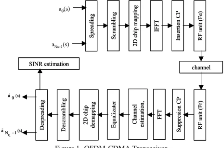
In this section, the generalized framework describing a OFDM-CDMA system is presented. Figure 1 shows a 2
dimensional (2D) spreading OFDM-CDMA
transmitter/receiver chain for a downlink communication with Nu users [1]. S p re ad in g S cr am b li n g 2 D c h ip m ap p in g IF F T In se rt io n C P R F u n it ( F e) R F u n it ( F r) channel S u p p re si o n C P F F T C h an n el es ti m at io n , E q u al iz at er 2 D c h ip d em ap p in g D es cr am b li n g D es p re ad in g SINR estimation a0(s) aNu-1(s) (s) 1 u N aˆ − (s) 0 aˆ S p re ad in g S cr am b li n g 2 D c h ip m ap p in g IF F T In se rt io n C P R F u n it ( F e) R F u n it ( F r) channel S u p p re si o n C P F F T C h an n el es ti m at io n , E q u al iz at er 2 D c h ip d em ap p in g D es cr am b li n g D es p re ad in g SINR estimation a0(s) aNu-1(s) (s) 1 u N aˆ − (s) 0 aˆ
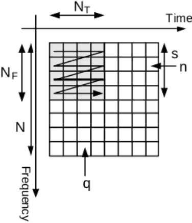
Each symbol is first spread by a Walsh-Hadamard sequence of Nc chips, and scrambled by a cell specific long pseudo random sequence. This scrambling code is used to minimize the multi-cell interference. The resulting samples are then allocated on the time/frequency grid as shown on Figure 2. The first NT samples are allocated in the time direction. The next blocks of NT chips are allocated identically on adjacent sub-carriers. Each bin with coordinate (n,q) represents the signal transmitted on the nth sub-carrier of the qth OFDM symbol. F re q u en c y NT NF N q s n Time
Figure 2- Time Frequency grid
The spreading factor is thus Nc= NF×NT where NF and NT are respectively the frequency and time domain spreading factors. Assuming a FFT of N points, each user transmits S=N/NF data symbols in an OFDM-CDMA block. Particularly, for NT =1, this resumes to a MC-CDMA scheme [7] and for NF =1, to MC-DS-CDMA [8].
Given the above notations, the signal at the IFFT input is:
(
)
1 ,..., 0 , 1 ,..., 0 ; 1 ,..., 0 ] [ ) ( 1 0 , − = − = − = + = +∑
− = F T N m T s m m m F q N n S s N q q nN C s a P n sN b u (1)s is the index referring to the sub band used for the transmission of the symbol am(s) of the mth user. Pm is its transmit power which is identical in all sub-bands, Cm,s represents its spreading sequence (chip by chip multiplication of the user assigned Walsh-Hadamard sequence and the cell specific scrambling code).
At the output of the IFFT, a cyclic prefix of ν samples is inserted to discard the inter symbol interference:
1 ,... ) ( 2 exp ) ( ) ( 1 0 1 0 − − = + + =
∑ ∑
− = − = N v k N n sN k j n sN b k x S s N n F F q q F π (2)After D/A conversion, transposition to the carrier frequency Fe by the RF unit, and transmission through the channel, the signal at the receiver side (Figure 1) is transposed to base band with the receiver carrier frequency Fr and sampled. The base-band time-discrete received signal, after guard time removal is then:
(
)
) ( 2 1 ;...; 0 ) ( 2 exp ) ( ) ( ) ( 1 0 v N q FT j and N u with u n u FT j k u g k x u r s q q q s N k q q q + ∆ = − = + + ∆ − =∑
− = π β β π (3)gq(k) (k = 0…W-1) are the complex coefficients of the discrete equivalent low-pass channel, with delay spread W samples (ν<W). Ts is the sampling clock period assumed identical at both sides. Notice that we use a discrete representation of the transmission with sampling-frequency Fs=1/Ts equal to the bandwidth of the real band pass transmit signal. Thus, the coefficients gq(k), of the discrete channel can be expressed as a function of the real parameters of the analog
channel ( ) 1 .sin
{
( )}
0 ) ( ) (∑
− = − =L l l q l q q Fs k Fs c k g α π τ . ) (l qα
andτ
q(l) are respectively the complex amplitudes and the delays of the lth multi-path, and sinc(x) = sin(x)/x. ∆F=Fr - Fe is the residual carrier frequency offset. The initial phase βq for the q-th OFDM symbols means that the receiver is perfectly synchronized at the beginning of each 2D symbol. nq(u) is a complex additive white Gaussian noise with variance σ2.Assuming a perfect synchronization of the FFT window, the receiver selects N consecutive samples and transposes them to the frequency domain thanks to the FFT.
The value of (wNF+p) th
sub-carrier of the qth OFDM symbol is given by :
(
)
( , , , , ) ( ) ) ( 1 0 1 0 p wN N q n p s w n sN b p wN R q F S s N n F q F q F + + + = +∑ ∑
− = − = φ (4)w is the desired sub-band index (w = 0,…, S-1) and p is the index of a sub-carrier in the wth sub-band (p = 0,…, NF-1).
φ(w,s,p,n,q) is the equivalent channel transfer function including the effect of the carrier frequency offset :
∑
− = + − = + 1 0 ) ( 2 ) ( 1 ) ( W k N n sN k j F F e k g N n sN h π is the FFT of the channel impulse response and ΨN(x) is the function defined by( )
)
sin(
)
sin(
x
N
Nx
x
Nπ
π
ψ
=
.Without loss of generality, we assume that one is interested by the symbols of user 0. In order to write the received signal with matrix-vector notation, the following matrices are defined: P = diag(P0,…, PNu-1) is the NuxNu diagonal matrix which entries are the power allocated to each user, Q = diag(P1,…,PNu-1) is the (Nu-1)x(Nu-1) diagonal matrix containing the power of the interfering users, C[s] = (C0[s], C1[s],…, CNu-1[s]) is the NcxNu matrix containing all the spreading codes used in the sth sub-band and
(
)
− + − + ∆ − × + ∆ × − + − + ∆ + = N n p N s w FT N j v N q FT j N n p N s w FT n sN h q n p s w F s s F s N F ) ( ) ( ) 1 ( exp ) ( 2 exp ) ( ) ( ) ( ) , , , , ( π π ψ φ (5)U[s] = (C1[s],…, CNu-1[s]) is the Nc x (Nu-1) matrix containing the codes of the interfering users in the sth sub-band. Both matrices C[s] and U[s] depend on sub-band index s because of the long scrambling code. We also define the vectors
[ ]
(
)
T Ns
a
s
a
s
a
u[
]
...,
],
[
1 0 −=
and~
a
[ ]
s
=
(
a
1[
s
],
...,
a
Nu−1[
s
]
)
Tcorresponding to the symbols of all and interfering users respectively transmitted in the sth sub-band.
The signal at the FFT output is multiplied by the one-tap channel equalization coefficients, descrambled and then it is multiplied by the spreading sequence of the reference user and summed over the chips to obtain the sample at the input of the decision device. The estimated symbol of the reference user on the sub-band w is then:
[ ]
[ ]
[ ]
[ ]
[ ]
[ ]
[ ]
[ ]
[ ]
( ) ( ) ) , ( ) ( ~ ) , ( ) ( ) ( ) , ( ) ( ) ( ˆ 0 3 1 0 0 2 0 1 0 0 0 0 0 3 2 1 0 0 w N w Z w C I s a P s C s w B w Z w C I w a Q w U w w B w Z w C I w a w C w w B w Z w C P I I I I I w a H S w s s H H H = = = = + + + =∑
− ≠ = (6)(Notation: AH is the transpose-conjugate of matrix A).
I0 represents the useful signal, I1 the Multiple Access Interference (MAI) generated in the same sub band w, I2 the interference generated by all users from other sub-bands and I3 the filtered noise. B(w,s) is a Nc×Nc matrix modeling the combined effect of channel attenuation and carrier frequency offset. It is defined by:
−
−
−
−
−
=
)
1
,
1
(
)
0
,
1
(
)
1
,
1
(
)
0
,
1
(
)
1
,
0
(
)
0
,
0
(
)
,
(
, , , , , , F F s w F s w F s w s w F s w s wN
N
A
N
A
N
A
A
N
A
A
s
w
B
L
L
M
O
M
M
O
L
L
− = ) 1 , , , , ( 0 0 0 0 0 0 ) 0 , , , , ( ) , ( , T s w N n p s w n p s w n p A φ φ L O O M M O O LIf there is no carrier offset, B(w,s) is the null matrix for w≠s and is diagonal for w=s. In this case, I2 is equal to zero, there is no inter carrier interference.
Z(w) is a Nc×Nc diagonal matrix which components are the equalizer‘s coefficients.
B. SINR evaluation
The symbols am(s) are assumed i.i.d. zero mean and unit variance random variables. The SINR for every sub band for one channel realisation is deduced from (6) by calculating the expectations of I0, I1, I2 and I3 : 2 3 2 2 2 1 2 0 I E I E I E I E SINR + + = (7)
The expectations in (7) are given by :
[ ]
[ ]
[ ]
[ ]
[ ]
[ ]
[ ]
[ ] [ ]
[ ]
(
H)
c S w s s H H H H H H H H H H H w Z w Z tr N I E w C w Z s w B s PC s C s w B w Z w C I E w C w Z w w B w QU w U w w B w Z w C I E w C w w B w Z w C P I E ) ( ) ( ) ( ) , ( ) , ( ) ( ) ( ) , ( ) , ( ) ( ) , ( ) ( 2 2 3 1 0 0 0 2 2 0 0 2 1 2 0 0 0 2 0 σ = = = =∑
− ≠ = (8)These expressions show that the SINR depends of actual value of the spreading codes. Hence (8) cannot be used practically due to its complexity and its sensitivity to the code allocation. In the sequel, we derive a new SINR formula that will be independent from the spreading codes while taking into account their orthogonality. This work relies on results of random matrix and free probability theories.
III. ASYMPTOTIC PERFORMANCE
Tse and Hanly [9] were the pioneer in the application of random matrix theory to CDMA systems analysis. They studied the asymptotic performance of the multi-user MMSE receiver for a CDMA system, with random spreading and synchronous reception. They found that the dependence of the SINR on the spreading codes was vanishing in the asymptotic regime (Nc and Nu →∞ while the ratio α=Nu/Nc is kept constant). The performances only depend on the system load α, noise variance and the power distribution. This work was then extended to a multipath fading channel in [10].
Unfortunately, the model with random spreading is not accurate for the downlink of actual CDMA or OFDM-CDMA systems, since it does not take into account the orthogonality between codes.
To solve this issue the authors of [11] proposed a trick. They assume that the spreading matrix C[s] is extracted from a Haar distributed unitary matrix. Such a matrix is random and isometric, which capture the orthogonality of conventional spreading matrices. This assumption allows applying very powerful results from the free probability theory. In [11] and [12], it was found that the dependence of the SINR on the spreading codes was also vanishing in the asymptotic regime. However, as opposed to [10], the orthogonality between codes was accounted for. In addition, it was found that the aforementioned assumption is only technical. The simulation results obtained in [11][12][13] with the combinaison of Walsh-Hadamard sequences and a scrambling code match very well with the theoretical model. This is achieved even for relatively small spreading factors (Nc≥32).
In order to evaluate the different terms of (8) and get ride off the dependence on the spreading codes, we apply three properties from the random matrix and free probability theories. The details of the computations are given in the Appendix. The final results are the following:
(
)
(
)
(
)
(
)
(
H)
c S s s s H H c c H H c c w Z w Z tr N I E w Z s w B s w B w Z tr N P I E w w B w Z tr N w Z w w B w w B w Z tr N P I E w w B w Z tr N P I E ) ( ) ( ) ( ) , ( ) , ( ) ( , ( ) ( 1 ) ( ) , ( ) , ( ) ( 1 , ( ) ( 1 2 2 3 1 ' 0 2 2 2 2 1 2 0 2 0 σ α α = = − = =∑
− ≠ = (9)α=Nu/Nc is the system load and
∑
− = − = 1 1 1 1 Nu m m u P N P is the
average power of the interfering users.
IV. PERFORMACE EVALUATION
We will now exploit (9) to compare MC-CDMA, MC-DS-CDMA and OFDM-MC-DS-CDMA spreading schemes. First, we assume that the receiver uses a MMSE equalizer :
(
)
(
)
γ φ φ + = + * 2 , , , , , , , , ) ( q p p w w q p p w w p wN zq Fγ is the inverse of the SNR per sub-carrier : 2 σ α
γ = P .
This implicitly assumes a perfect estimation of the rotated and attenuated channel frequency response on sub-carrier
(wNF+p):
(
)
exp(
(
2( ) 1)
)
) ( ) , , , , (wwppq =hwNF+pψN ∆FTs jπ∆FTs qN+v +N− φIn order to compare the different spreading scheme, we define the parameter: I(w)=EI1 2+EI2 2+EI3 2. With these assumptions the different terms of (9) become:
( ) ( ) ( ) ( ) ( ) ( ) ( ) ( )
∑
∑
∑∑∑
∑
− = − = − = − = − = ∗ − = + ∆ + ∆ + + + ∆ + ∆ + − + ∆ + − + − + ∆ ∆ + + = + ∆ + ∆ + = 1 0 2 2 N N 2 2 1 0 2 N 2 N 1 0 1 0 1 0 2 2 N N N 2 1 0 2 N 2 N 2 0 2 0 ) ( ) ( ) ( ) ( 1 ) ( N ) ( ) ( ) ( ) ( ) ( ) ( F F F F F N p F s s F F N p F s s F F S s N p N n F s F s s F F F N p F s s F F FT p wN h FT p wN h N FT p wN h FT p wN h N P FT p wN h n p N s w FT FT n sN h p wN h N P w I FT p wN h FT p wN h N P I E γ ψ ψ σ γ ψ ψ α γ ψ ψ ψ α γ ψ ψ (10 )In order to validate the asymptotic formula, we first compare the result computed with (7) and (10) with the SINR measured via Monte Carlo simulations. The simulations assumptions are the followings:
• FFT size: N=64, Spreading factor: Nc= 32 chips, QPSK modulation.
• Scrambling code: concatenation of 19 Gold codes of 128 chips each.
• Spreading schemes: MC-CDMA: (NF=32,
NT=1), OFDM-CDMA: (NF=8, NT=4), MC-DS-CDMA: (NF=1, NT=32).
Figure 3 illustrates the comparison between theoretical and simulated SINRs for BRAN A channel model [17]. The SINRs have been measured in the first sub-band (w=0). Due to the variations of the channel caused by the mobile speed (3 km/h), we compare the means SINRs. The simulations performances are realized for a mean ratio Eb/ N0 of 20 dB. It
is given by 2 0 1 0 2 ) ( 0 . 2 ) ( . P E N N N E L l l b σ α ν
∑
− = += where α( l) 2 is the power of
each multipath of the channel. Figure 3 shows that our theoretical model matches perfectly with simulations, even for a relatively small spreading factor (Nc=32). As for conventional multicarrier systems, the degradation becomes noticeable for N∆FT > 1%. The sensitivity of the 3 spreading schemes to carrier offset is comparable.
-5 0 5 10 15 20 25 0,001 0,01 0,1 1 NDFT S IN R ( d B ) MC-CDMA Asymp W=0 MC-CDMA Sim W=0 MC-DS-CDMA Asymp W=0 MC-DS-CDMA Sim W=0 OFDM-CDMA Asymp W=0 OFDM-CDMA Sim W=0
Figure 3: validation of theoretical model (BRAN A).
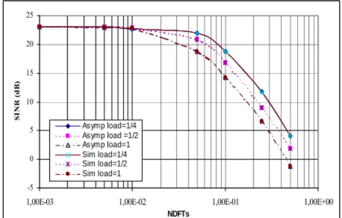
Figure 4 presents the sensitivity of the MC-DS-CDMA scheme to system load for a gaussian channel. As predicted by equation (10), the degradation increases with the load. This result is in contradiction with the conclusion of [5] which stated that the MC-DS-CDMA scheme was not sensitive to system load since [5] supposes that in the latter that the MAI is eliminated by the equalizer.
-5 0 5 10 15 20 25
1,00E-03 1,00E-02 1,00E-01 1,00E+00
NDFTs S I N R ( d B ) Asymp load=1/4 Asymp load =1/2 Asymp load=1 Sim load=1/4 Sim load=1/2 Sim load=1
Figure 4: sensitivity of MC-DS-CDMA to system load (Gaussian channel).
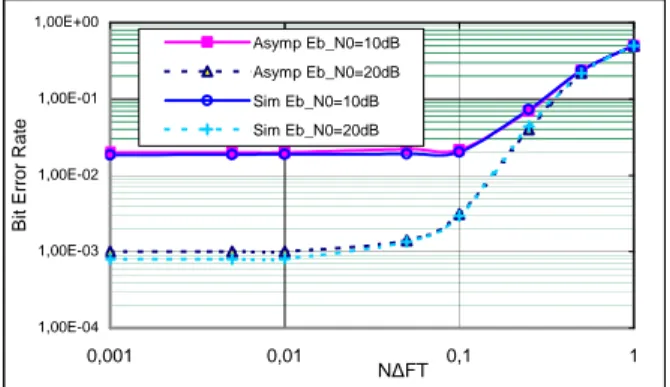
On other side, it was demonstrated in [18] that the MAI at the output of a linear receiver is asymptotically gaussian, as Nc →∞. This property allows using the SINR as a criterion to determine the system performance. For a QPSK modulation, the Bit Error Ratio (BER) is related to the SINR by:
(
)
[
Q SINR]
E
BER= (11)
Q(x) is the gaussian tail function, and the expectation is taken over the channel realizations. This is validated in Figure 5, which shows that the BER obtained with (11) and (10)
matches perfectly with Monte Carlo simulations. However, it is known that the channel coding scheme has a huge impact on the comparison between OFDM-CDMA and COFDM schemes [19]. As MC-DS-CDMA is very similar to a COFDM system, the channel coding scheme must be considered for the comparison between spreading schemes.
1,00E-04 1,00E-03 1,00E-02 1,00E-01 1,00E+00 0,001 0,01 0,1 1 N∆FT B it E rr o r R a te Asymp Eb_N0=10dB Asymp Eb_N0=20dB Sim Eb_N0=10dB Sim Eb_N0=20dB
Figure 5: BER comparison between asymptotic model and simulation (Bran A channel OFDM-CDMA).
Since the theoretical model has been validated, we will exploit equation (10) to give more insight on the sensitivities of MC-CDMA and MC-DS-MC-CDMA to carrier frequency offset. If the receiver implements a zero-forcing (ZF) equalizer (γ=0), equation (10) becomes:
(
)
(
)
∑
∑ ∑ ∑
− = − = − = − = ∆ + + − ∆ + ∆ + − + − + = = 1 0 2 N 2 1 0 1 0 1 0 2 N N 0 2 0 ) ( 1 ) ( N ) ( ) ( ) ( F F F N p F s F S s N p N n F s F s F F FT p wN h N P FT p wN h n p N s w FT n sN h N P w I P I E ψ σ α ψ ψ αLet us note IMC-DS-CDMA(w) the interference power of the wth sub-carrier of a MC-DS-CDMA scheme (NF=1, NT=N, S=N), and IMC-CDMA the total interference for a pure MC-CDMA system (NF= N, NT=1, S=1). Based on the above formula, we observe that:
∑
− = − − − = 1 0 ) ( 1 N w CDMA DS MC CDMA MC I w N I (12)With a ZF equalizer, the total interference power of a MC-CDMA system is the average of the interference experienced by each sub-carrier in a MC-DS-CDMA system. For a Gaussian channel, it is easily proven that I(w+k) = I(w). This is due to the periodicity of function ψN(x) (ψN(x+1)= ψN(x)). Hence, as shown in Figure 6, the interference power is independent of the carrier index. The legend ‘mean MC-DS-CDMA’ refers to the interference computed according to equation (12). The accuracy of equation (12) for a ZF equalizer in a BRAN A channel is demonstrated in Figure 7
by giving the mean over channel realizations of the total interference power. Figure 8 shows that it is not the case for a MMSE equalizer. 0,02 0,025 0,03 0,035 0,04 0 10 20 30 40 50 60 70 carrier index w I[ w ] MC-CDMA MC-DS-CDMA Mean MC-DS-CDMA
Figure 6: Interference power (ZF and Gaussian channel) ∆F=1560ppm.
0 0,05 0,1 0,15 0,2 0,25 0,3 0,35 0,4 0,45 0 10 20 30 40 50 60 70 carrier index w I[ w ] MC-CDMA MC-DS-CDMA Mean MC-DS-CDMA
Figure 7: Mean Interference power (ZF and BRAN A channel) ∆F=1560ppm.
0 0,01 0,02 0,03 0,04 0,05 0,06 0,07 0 10 20 30 40 50 60 70 carrier index w I[ w ] MC-CDMA MC-DS-CDMA Mean MC-DS-CDMA
Figure 8: Mean Interference power (MMSE BRAN A channel) ∆F=1560ppm. V. CONCLUSION
In this article, we have investigated the effect of carrier frequency offset on the performance of 2 dimensional OFDM-CDMA spreading schemes. A new analytical expression of the SINR has been derived. It is valid for various kind of single user equalizer (MMSE, ZF) and for any frequency selective channel. It is independent of the actual value of the spreading codes but takes their orthogonality into account. Exploiting this model, we found that, for a ZF equalizer, the total interference power of a MC-CDMA system is the average of the interference experienced by each sub-carrier in a MC-DS-CDMA system.
VI. APPENDIX
In this section, the 3 properties from the random matrix and free probability theories are first defined. Then their application for the computation of (9) is detailed.
Property 1: If A is a
N
c×
N
c uniformly bounded deterministic matrix and = 1 ( m(0),...., m( c−1))c m c c N N C where ) (l
cm 's are iid complex random variables with zero mean, unit variance and finite eighth order moment, then [10]:
) ( 1 A tr N AC C c N m H m c → →∞ (13) 0
C is obtained by the multiplication of a Walsh-Hadamard sequence with a long scrambling code. Hence, the assumptions needed for (13) are easily satisfied. This property is used to evaluate EI02,
2 1 I
E , EI22and EI32.
Property 2: Let C be a Haar distributed unitary matrix of size Nc×Nu [11]. C=(C0U) can be decomposed into a vector
0
C of size
N
c and a matrix U of size Nc × (Nu − 1). Given these assumptions, it is proven in [12] that:(
H)
N H P I C C UQU c − 0 0 → →∞ α (14)α=Nu/Nc is the system load and
∑
− = − = 1 1 1 1 Nu m m u P N P is the
average power of the interfering users. This property is used to evaluate EI12.
Property 3: If C is generated from a Nc×Nc Haar unitary random matrix then matrices C
[ ]
sQC H[ ]
s and) ( ) , ( ) , ( ) (w Bws BwsZw
Z H H are asymptotically free almost
everywhere [15]. In other words, verifying the above conditions, one can conclude:
[ ]
[ ]
(
)
(
)
tr(
C[ ]
sPC[ ]
s)
N w Z s w B s w B w Z tr N w Z s w B s PC s C s w B w Z tr N H c H H c N H H H c c 1 ) ( ) , ( ) , ( ) ( 1 ) ( ) , ( ) , ( ) ( 1 × → →∞ (15)For definition of freeness, the reader may refer to [11] for more details.
Assuming that C0[w]is random (13) is used to evaluate 2
0 I
E . Since we use a long scrambling code, C0[w] and C [s] are independent for w≠s. Using (13),
2 2
I
E
becomes :[ ]
[ ]
(
)
∑
− ≠ = = 1 0 2 2 ( ) ( , ) ( , ) ( ) S w s s H H H w Z s w B s PC s C s w B w Z tr I E (16)This computation method has initially been applied for the analysis of multi-cell downlink CDMA systems in [16].
Applying (14) for the computations of EI12and (15) for the
computations of EI22in (16), (9) is obtained.
REFERENCES
[1] N. Maeda, Y. Kishiyama, H. Atarashi and M. Sawahashi, "Variable Spreading Factor OFCDM with Two Dimensional Spreading that Prioritizes Time domain Spreading for Forward Link Broadband Wireless Access", Proc. of VTC spring 2003, April 2003, Jeju, Korea. [2] A. Persson, T. Ottosson, and E. Ström, "Time-Frequency Localized
CDMA for Downlink Multi-Carrier Systems", IEEE 7th Int. Symp. On
Spread-Spectrum Tech. & Appl., pp. 118-122., Prague, Czech Republic, Sept 2-5, 2002.
[3] T. Pollet, M. Van Bladel and M. Moeneclaey.; "BER sensitivity of OFDM systems to carrier frequency offset and Wiener phase noise" IEEE Transactions on Communications, Vol: 43 , Issue: 234, Feb./March/April 1995.
[4] P. H. Moose, "A technique for Orthogonal Frequency Division Multiplexing Frequency Offset Correction", IEEE Trans. on Communications, Vol. 42, Issue: 10, October 1994.
[5] H. Steendam and M. Moeneclaey, "Comparison of the sensitivities of MC-CDMA and MC-DS-CDMA to carrier frequency offset", Proc. of Symposium on Communications and Vehicular Technology, 2000. SCVT-2000, pp.166 – 173, Oct 2000.
[6] L. Tomba and W. A. Krzymien, "Sensitivity of the MC-CDMA Access Scheme to Carrier Phase Noise and Frequency Offset", IEEE Trans. on Vehicular Technologies, Vol. 48, Issue: 5, May 1999.
[7] N. Yee, JP. Linnartz and G. Fetteweis, "Multi-Carrier CDMA in Indoors wireless radio networks", proc. of PIMRC' 93 Yokohama Japan, pp:109-113.
[8] V. M. da Silva and E. S. Sousa , "Performance of Orthogonal CDMA sequences for quasi-synchronous communication systems" Proc. of IEEE ICUPC’93, Ottawa, canada, Octobre 1993.
[9] D.N.C. Tse, S.V. Hanly, "Linear multiuser receivers: effective interference, effective bandwidth and user capacity", IEEE Trans. on Information Theory, Vol. 45, Issue: 2, March 1999.
[10] J. Evans and D.N.C Tse, "Large system performance of linear multiuser receivers in multipath fading channels", IEEE Trans. on Information Theory, Vol. 46, Issue: 6, Sept. 2000.
[11] M. Debbah, W. Hachem, P. Loubaton and M. de Courville, "MMSE analysis of Certain Large Isometric Random Precoded Systems", IEEE Trans. on Information theory, Vol. 43, Issue: 5, May 2003.
[12] J.M. Chaufray, W. Hachem and Ph. Loubaton, "Asymptotical Analysis of Optimum and Sub-Optimum CDMA Downlink MMSE Receivers", Information Theory, IEEE Transactions on , Vol: 50, Issue: 11, Nov. 2004.
[13] P. Jallon, M. des Noes, D. Ktenas and J. M. Brossier, "Asymptotic analysis of the multiuser MMSE receiver for the downlink of a MC-CDMA system" , Proc. of VTC spring 2003, April 2003, Jeju, Korea. [14] Y. Nasser, M. des Noes, L. Ros and G. Jourdain, "SINR estimation of
OFDM-CDMA systems with constant timing offset: a large system analysis", to appear in proceedings PIMRC' 2005, September 2005, Berlin, Germany.
[15] W. Hachem, "simple polynomials for CDMA downlink transmissions on frequency selectyive channels" IEEE Trans. on Information Theory, Vol: 50, Issue: 1, pp: 164 – 171, January 2004
[16] T.B. Abdallah and M. Debbah, "Downlink CDMA: to cell or not to cell", 12th European Signal Processing Conference (EUSIPCO 2004), Vienna, Austria.
[17] J. Medbo, H. Andersson, P. Schramm and H. Asplund, "Channel models for HIPERLAN/2 in different indoor scenarios", COST 259, TD98, Bradford, April1998.
[18] J. Zhang, E. Chong, and D. Tse, "Output MAI Distributions of Linear MMSE Multiuser Receivers in CDMA Systems", IEEE Trans. on Information Theory, Vol. 47, Issue: 3 , March 2001.
[19] S. Kaiser, "Trade-off between Channel Coding and Spreading in Multi-Carrier CDMA Systems", in Proc. of ISSSTA’96, Mainz, Germany, pp. 1366-1370, Sept. 1996