HAL Id: hal-01657605
https://hal.archives-ouvertes.fr/hal-01657605
Submitted on 11 Dec 2017
HAL is a multi-disciplinary open access
archive for the deposit and dissemination of
sci-entific research documents, whether they are
pub-lished or not. The documents may come from
L’archive ouverte pluridisciplinaire HAL, est
destinée au dépôt et à la diffusion de documents
scientifiques de niveau recherche, publiés ou non,
émanant des établissements d’enseignement et de
Security Architecture for Point-to-Point Splitting
Protocols
Benoit Badrignans, Vincent Danjean, Jean-Guillaume Dumas, Philippe
Elbaz-Vincent, Sabine Machenaud, Jean-Baptiste Orfila, Florian
Pebay-Peyroula, François Pebay-Peyroula, Marie-Laure Potet, Maxime Puys,
et al.
To cite this version:
Benoit Badrignans, Vincent Danjean, Jean-Guillaume Dumas, Philippe Elbaz-Vincent, Sabine
Machenaud, et al.. Security Architecture for PointtoPoint Splitting Protocols. WCICSS 2017
-IEEE World Congress on Industrial Control Systems Security, Dec 2017, Cambridge, United
King-dom. �hal-01657605�
Security Architecture for Point-to-Point Splitting
Protocols
∗
Benoˆıt Badrignans
1, Vincent Danjean
2,3, Jean-Guillaume Dumas
2,4,
Philippe Elbaz-Vincent
2,6, Sabine Machenaud
8, Jean-Baptiste Orfila
2,4,
Florian Pebay-Peyroula
7,2, Franc¸ois Pebay-Peyroula
8, Marie-Laure
Potet
2,5, Maxime Puys
2,5, Jean-Luc Richier
2,3, and Jean-Louis Roch
2,51
Secl¯ab
† 2Universit´e Grenoble-Alpes
‡ 3LIG
4LJK
5Verimag
6IF
7CEA-LETI
§ 8Atos
¶December 11, 2017
AbstractThe security of industrial supervisory control and data acquisition systems (SCADA) has become a major concern since the Stuxnet worm in 2010. As these systems are connected to the physical world, this makes them possibly hazardous if a malicious attacker is able to take over their control. SCADA can live up to 40 years, are particularly hard to patch, and quite often have no security feature at all. Thus, rather than securing them, network segregation is often used to prevent attackers from entering the industrial system. In this paper, we propose a generic solution: embed a point-to-point splitting protocol within a physical device, thus able to physically isolate networks, perform deep packet inspection and also provide encryption if necessary. We obtain a kind of next generation firewall, encompassing at least both diode and firewall features, for which conformity to security policies can be ensured. Then we define a set of associated security properties for such devices and the requirements for such a device’s security architecture and filtering rules. Finally, we propose a secure hardware implementation.
∗This work is partly funded by BPIFrance via theARAMISPIA project P3342-146798 – FSN AAP S´ecurit´e Num´erique n◦3.
†[email protected] ‡firstname.lastname@univ-grenoble-alpes §[email protected]
1
Introduction
The security of industrial networks has become an important research area in recent years. Attacks against Industrial Control Systems (ICS), including supervisory control and data acquisition (SCADA) systems, are common (see, e.g., the yearly global risks report of the world economic forum or [3]). Those attacks often succeed since part of these systems were only designed to fulfill functional requirements without any secu-rity reinforcements. Moreover, due to the long lifetime of these systems (potentially between 20 and 40 years) and the complexity to apply security patches, segregation is often proposed as a solution. In this situation, the system is split in zones of possible different security levels and a security device is inserted between each zone. In this way, if a zone is compromised others should not be affected. As of today, two types of devices can perform such segregation: firewalls and diodes [6]. However diodes are too limited and with firewalls, if a vulnerability is exploited on the security device itself, then the whole device might be compromised since there is no physical sepa-ration between its two sides. More recently, next-genesepa-ration firewalls (NGFW) have been introduced that generalize firewalls by adding more thorough flow analysis (for instance of ciphered flow), access control or intrusion detection systems [20,15,23]. To enhance the security of SCADA systems, it is not only necessary to add such gen-eralized filtering, but it would also be important to provide encryption capabilities and low-level filtering. Both these additions should be added to existing systems and not degrade their performance.
Contributions. In this paper, we propose a solution based on a physical device managing protocols splitting (or disruption) within a network. Our proposed device, deployed between two communicating entities, provides a physical and logical sepa-ration between them. Then, in case of attacks on one side, the device will act as a gate and stop the attacks; thus reducing drastically potential consequences. Now, the deployment of some new equipment into an existing network could be tedious. Indeed the constraints range is large: high availability, real time latency, etc. Thus, to facilitate integration into the network the device is designed to be as flexible as possible and dependent on the network requirements. In particular, the device should split several kind of protocols with security features, from OPC-UA TLS encryption, to SFTP or FTPS, its key management is crucial. Indeed, one way to provide transparent ciphering mechanism, is to place such a device at both ends of the channel that has to be secured. Overall, we view such a device in an abstract way as a next-generation firewall provid-ing encryption/decryption. We also propose a formalization of the associated security requirements and features as well as an associated generic security architecture of such a device, including for instance a public key infrastructure (PKI) and hardware security modules (HSM) with key stores.
Related Work. The security of industrial systems has become an hot topic in the past years with an increasing number of attacks [4]. It has come to the point that nu-merous government agencies are publishing white-papers to ensure that their countries’ industry could survive a cyberwar. For instance, in 2011 the US National Institute of Standards and Technology released a detailed survey on the topic [19] just like the next year by the French ANSSI [1]. Several other surveys and norms have then fol-lowed [7,22,10], but up to our knowledge none of them formalize all the
functionali-ties we identified as security requirements for point-to-point splitting protocols. Then, our splitting can be seen as an evolution from the proposition [12] of applying split-ting to VPN gateways which would encompass also security features and architectures adapted to industrial control systems, as, e.g., in [5], but directly suited to a device comprising keys and certificates.
Outline. In Section2, we first describe the requirements and generic architecture of such a device. Then in Section3, we propose an example of implementation. In Section4and5we respectively discuss two critical parts of protocol splitting: public key infrastructure and stream analysis. Finally, in Section6, we provide a security analysis of our solution and conclude in Section7.
2
A Protocol Splitting Device
We start by detailing the goals and security requirements of a splitting protocol device and then propose a generic design.
2.1 Device Aim
Our proposition for the security of SCADA systems is to use dedicated physical de-vices embedding a point-to-point splitting protocol: such a device is able to physically isolate networks and perform deep packet inspection. Now, such a device aims to be in-cluded into an existing infrastructure. The security of firewalls has been widely studied and several public or private organizations have proposed protection profiles to detail their security features, as well as the threats and requirements in a certification proce-dure. For instance, the French ANSSI published several protection profiles specifically intended to industrial systems. Due to the novelty of protocol splitting, no protec-tion profile exists for such devices yet. The closest protecprotec-tion profile available would concerns industrial firewalls [2]. Other protection profiles for classical IT firewalls are also proposed for instance by Common Criteria [8]. According to those documents, the main features a firewall should include are: network filtering, protocol analysis, admin-istration functions, local logging and remote logging. Such firewall could be deployed between existing networks to increase the security, or into two distinct architectures to allow new communications between them. However, a protocol splitting device allows to split point-to-point protocols and thus brings more security than a simple firewall. First it breaks the spread of attacks, and second it eases the analysis of the stream by transforming it into a known intermediate form. Even if the protocol splitting device we present shares many goals with a classical firewall, we show in Section2.2that there exists key differences in the security features requirements.
2.2 Security Features and Requirements
To maintain the features detailed in Section2.1in an hostile environment, the de-vice must provide security features. Still according to protection profiles, the minimal security features we consider for a firewall are displayed below, sorted on the main security need they cover.
Robustness. It is the ability to manage errors during execution and cope with er-roneous inputs. Within a firewall it is related to syntax and semantic of configuration files, administrator commands and packets to filter:
• ROB.1 – Malformed input management; • ROB.2 – Filtering policy enforcement; • ROB.3 – Protocol conformity analysis.
Authenticity. (or authentication) is to ensure that an entity is the one it pretends to be. On the firewall, it applies to any administrator configuring the firewall and the firewall could also perform authentication on the messages it filters:
• AUT.1 – Secure connection with the authentication server; • AUT.2 – Secure authentication on administration interface; • AUT.3 – Access control policy.
Confidentiality. This is the guaranty that only authorized entities will access the information they have been granted. Within the firewall it can apply to the configuration (e.g., the rules) depending on the context but mainly in the case of encrypted messages to filter, it applies to the cryptographic keys stored inside the filter:
• CON.1 – Secure storage of secrets; • CON.2 – Configuration confidentiality.
Integrity. It is the preservation in time of data consistency. It can apply to various contexts in the firewall including configuration and outputs:
• INT.1 – Firmware signature; • INT.2 – Configuration integrity; • INT.3 – Logs integrity;
• INT.4 – Alarms integrity.
Isolation.Unlike firewalls, a protocol splitting device also aims to provide isolation properties, as would be expected, e.g., from a diode. Thus, to complete the properties described above for a firewall, we propose the following security feature for a protocol splitting device. Isolation ensures that a running process is not able to access and/or alter any information from another one. It can apply to various components such as: • ISO.1 – Memory isolation;
• ISO.2 – Peripheral isolation; • ISO.3 – Computations isolation; • ISO.4 – Network segregation.
We would have expected isolation properties to be present in protection profiles re-lated to diodes, but to the best of our knowledge such properties are not mentioned. Af-ter having identified these requirements, we will show along this paper how a protocol splitting device can extend simple firewalls and implement all these required properties. 2.3 Architecture of a Protocol Splitting Device
One of the main objective of the device is to split protocols, partly to provide net-works isolation. From an hardware point of view, this implies that the device is at least divided in three distinct parts: two parts are used to communicate with external entities and the third one is dedicated to the security services of the device. For instance, exter-nal entities could be the client and the server into a TLS exchange. Within the device, we call Hatches both parts dedicated to the external communications and the middle part is called the Core. Since each part represents a specific entity, it can be materi-alized by a dedicated hardware. From an abstract point of view, the three entities are seen as independent: thus, a common implementation could use three distinct System-on-Chips(SoC), each one including at least its own memory and CPU, validating both
ISO.1 and ISO.3. This way, the isolation is inherent to the construction. Commu-nications between each internal entities is realized through an internal and dedicated communication interface, e.g., some serial or parallel port.
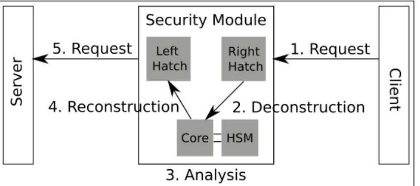
The hatches are designed to receive and transmit the network stream. Without lost of generality, let us suppose that the server (S) for a generic secure communication protocol is situated at the left side of the device, and the client (C) is on the right side. The scenario is summarized in Figure1.
1. Request 5. Request Client Server 2. Deconstruction 3. Analysis 4. Reconstruction Right Hatch Left Hatch Core Security Module HSM
Figure 1: Client & Server using the security device, with point-to-point splitting In this configuration, a client sends a request to the server. As in a kind of autho-rized Man-In-The-Middle, the server intercepts the request on its right hatch. The main difference with an attack is about the key management: even if the client is willing to communicate with the server, the device will transparently acts as the server by using a dedicated key pair (see section4.1). Once the request has been received, the right hatch deciphers it, and deconstructs the message. The obtained information, such as message address or functional content, is rewritten into an intermediate internal language, and transferred to the core.
The core’s main tasks are about the security management. It should have access to an Hardware Security Device. It receives the stream from the right hatches, and analy-ses it using filtering rules [16]. In case of malicious behavior detection, the device acts depending on the defined policy: it could write into a log file which will be sent to the Security Information and Event Management system(SIEM), and/or sound the alarm directly (validating properties INT.3 and INT.4). In monitoring systems like SCADA, the filtering operation also allows to simply discard messages. Once the stream analysis has been realized, the core transmits it to the left hatch.
Finally, the left hatch has to reconstruct the correct network frame from the in-ternal language. All applicative information contained into the original message are reused ; but all the transport information (MAC, TCP/IP UDP/IP) are destroyed and reconstructed on the other hatch. This means that the device is transparent for exter-nal entities. Theoretically, by removing the device between previously communicating entities and rewiring them as before, the entities should be able to communicate again. The server response follows the same pattern, where right and left hatches opera-tions are exchanged. The protocol splitting has been materialized by packets
decon-struction, analysis and reconstruction. Hence, a point-to-point connection between a client and a server is now transformed into two point-to-point connections: the first one between the client and the device, the second one between the device and the server.
3
An Example of Implementation
The difficulty is thus to create such a device, potentially capable of bringing an unri-valed level of security to existing or new industrial control system architectures. We thus next propose hardware and software for an example implementation of a protocol splitting device that supplies the required security functionalities in a single and robust system. Moreover, this system can be implemented without impacting applications in the existing industrial control system, while simultaneously providing protection from attacks. We first detail some implementation choices for the hatches and the core and then propose to add an HSM (Hardware Security Device) to the design, in order to deal with all the security features.
3.1 Device Architecture
General Architecture. Both left and right hatches are made with the same com-ponents. Considering they are used to communicate with external entities, they own network communication interfaces (e.g., an Ethernet Port). The processing of the re-ceived requests (resp. responses, depending on the hatch side) is done by a secure operating system. The OS is in charge of communications protocols (from configura-tion to packets exchanges), packets deconstrucconfigura-tion, and communicaconfigura-tion with the core through a dedicated internal interface, thus validating properties ISO.2 and ISO.4.
The core architecture is similar to that of the hatches. It is also based on an ARM processor. The core represents the critical part of the device and is directly linked to the HSM. It handles the network stream analysis along with administrative tasks. In order to obtain a kind of Trusted Execution Environment, the OS is based on a secure kernel, in the same vein as [14]. Cryptographic operations are realized on a dedicated FPGA chip. A dedicated library has been developed to respond to the tight execution time constraints. The library supports current cryptographic recommendations in terms of security parameters. In particular, it manages the Elliptic Curves Cryptography and takes its sources in the work [9].
Secure Boot Sequence. In order to be resistant against attacks aiming at replacing the embedded software of the device, a secure boot mechanism is mandatory. A way to implement this feature is to use the process described in [17]. The idea is to add integrity checks from a software to the next one during the boot sequence. Hence, at each step, the integrity of the next piece of software is guaranteed. The origin of this verification sequence is a security feature provided by recent FPGAs, where their initial bitstream is ciphered using a symmetric key, securely stored into a dedicated permanent memory [21].
3.2 Embedded Hardware Security Device
As already mentioned, the device embeds a Hardware Security Device (HSM) con-nected to its core. It provides security features to the core and to the hatches. As for
many HSM, its goal is to safeguard and manage digital keys and provide secure crypto-graphic processing. It also provides tamper evidence and tamper resistance. An HSM fitted for embedded system constraints, for instance specially developed for industrial and lightweight applications should be used. As reported in [18], existing trusted tech-nologies adapted to embedded systems are usually more dedicated to ensure a secure boot or to provide trusted applications rather than providing secure storage and crypto-graphic operation secure services. Smart-cards could also be used but might lack mul-tiuser management and provide insufficiently efficient symmetric cryptography. Still, we were able to design our own HSM, constrained in terms of power consumption (< 2W ), footprint (< 10cm2) and bill-of-material (< $100), but which still provides
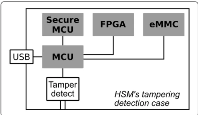
sufficient levels of performance and robustness to attacks. This is detailed next. Hardware architecture.To fulfill these requirements without downgrading the per-formance nor the robustness, the architecture, shown in Figure2, is based on a trade-off between three main components. A generic purpose Microcontroller Unit (MCU) acts
Secure
MCU FPGA eMMC
MCU USB HSM's tampering detection case Tamper detect
Figure 2: Embedded hardware security module
as an orchestra conductor. It receives the “job” requests from the main system, man-ages that the “jobs” are executed as requested and sends the answer back to core. Then a Field Programmable Gate Array (FPGA) implements the symmetric block cryptog-raphy that may be computed on data streams. The FPGA brings high throughput and low latency cryptographic processing. Then a secure microcontroller (Secure MCU) ensures the safeguard of master or critical keys and performs the asymmetric cryptog-raphy using those keys. It brings the robustness to physical attacks. An embedded Multimedia Card (eMMC) is associated, for non-volatile storage, where data is always encrypted before being stored. It brings a high amount of storage to the HSM. If HSM keys and cryptographic mechanisms are dispatched on purpose on each of these three components, the hardware architecture allows the HSM to benefit from each of the components security or performance features. A tamper detection loop is glued inside the HSM metal case and is connected on two microcontroller pins. This loop is ac-tive when the HSM is powered-on and can detect a physical intrusion inside its case. When the case tampering is detected, the MCU erases all volatile plaintext data from the MCU and the FPGA and then shuts down all the components. No plaintext in-formation is stored neither on the MCU internal flash nor on the eMMC. The secure
microcontroller that stores no volatile secrets has his own tamper detection features. Communication between the HSM and the core. The HSM is connected to the core through an USB port, it is enumerated as a pseudo serial port (ttyUSB). A library installed on the core operating system wraps the serial port and exposes a PKCS#11 application programming interface (API). When the HSM is connected, this API shows one slot and one token. PKCS#11 calls are serialized within the library, then sent to the HSM through the USB serial port, de-serialized on the MCU and executed on the MCU or on the FPGA or on the secure MCU. The HSM implements all PKCS#11 functions, but for now only a subset of the cryptographic mechanisms. The HSM provides a mul-tiuser extension to the PKCS#11 standard. By default the standardPKCS11specifies: A Security Officer (SO) that can manage the token and the user PIN, but in any case has access to the data. A user which can store public or private keys or objects and which can process cryptographic operations on these object remotely on the token. In the multiuser extension, the Security Officer keeps the same roles. Each user has his own private objects and cannot access to other user’s private objects; while public objects are accessible to all logged in users. In order to keep the compatibility to the PKCS#11 standard, the C Login function prototype is not modified, the parameter used for the user PIN has this format: <login:PIN>. If C Login is called only with the PIN (without ”login”), the token logs the main user in. As of today this main user has the same level of rights than the other users, but it would be feasible to upgrade him as a ”super user” which could thus access all the user’s private data.
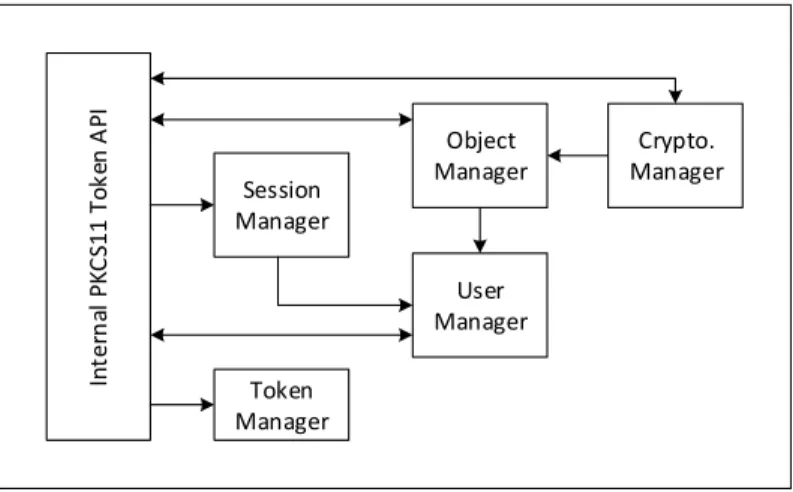
Token Manager In te rn al P K C S11 T o k en A P I Object Manager Crypto. Manager User Manager Session Manager
Figure 3: HSM embedded software architecture
The PKCS#11 code is mainly executed in the MCU. The code is splitted into basic tasks that are scheduled by FreeRTOS, a real time and lightweight operating system. Figure3 shows the embedded software architecture: PKCS#11 calls from the core are serialized on the USB port and de-serialized to be replicated on the HSM internal ”Token API”. PKCS#11 sessions are maintained by the ”Session Manager”, beyond public sessions, users are authenticated by the ”User Manager” upon login . The ”User manager” also handle creation, PIN update, and deletion of the users. PKCS#11 objects are maintained by the ”Object manager”, its role is to provide accessors for reading and
writing objects, to provide objects access for cryptographic operations and to check user authorization for accessing the objects. The ”Cryptographic Device” implements PKCS#11 mechanisms, this device uses internally the mbedTLS library. The ”Token Manager” handle the HSM initialization, including function to set the Security Officer’s first PIN.
Security architecture for point-to-point splitting protocols.The HSM in the device for splitting protocol is involved in two major phases: the configuration of the device itself and the operation of the device. The HSM is configured by the core directly through the PKCS#11 API thanks to the pkcs11-tool command line. The configura-tion process mainly involves the creaconfigura-tion of the users and the populaconfigura-tion of certificates into the HSM (see Section4). In order to ease the process, the calls to pkcs11-tool are packaged into scripts. A user is created for the core and for each hatches; their private objects are by consequence securely partitioned into the HSM. Then, during any operational phase, the HSM is used to handle the handshake of secure connections between clients and servers of the device. To set the TLS connections between clients and servers, the hatches have a classical TCP/IP stack, then the OPC-UA proxies del-egate the TLS handshake to the ”openssl” library that is configured to use an external PKCS#11 ”engine”. Thanks to this, asymmetric cryptographic calls from openssl are redirected through the PKCS#11 engine to the HSM. To allow hatches to access the HSM, we developed a PCKS#11 proxy that exposes the same API than the HSM using the communication bus between hatch and core. Overall, certificates can be checked, both parties can be authenticated and secure session keys can be established.
4
Keys and Certificates Management
In this section, we describe the security architecture related to the device. As the device is integrated into a security architecture, the certificates and keys management is cru-cial. We start by defining the involved entities, along with their certificates and keys. Then, we explain each phase of the device lifetime, from its manufacturing to its use in production.
4.1 Security Architecture and PKI
In the following, we describe the key pairs and certificates needed with regards to their use (i.e., to boot and setup the device, to administrate it, and to operate the protocol splitting). Usually, these keys and certificates are stored into a secured area located within the HSM (as required by the CON.1 property), and called the trust anchor store.
Entities. From manufacturing to its administration, many actors interact with the device:
• Manufacturer: the device seller. It also furnishes firmware updates;
• Integrator: the entity which deploys the device into the customer network. It also provides the first configuration. It may also afterwards manage a complete PKI for the customer;
• Customers: the entities which are willing to deploy the device into their infrastruc-ture;
• Trusted employees: those entities will connect themselves to the device in order to perform updates, or maintenance tasks depending on their attributed role;
• Communicating entities: external entities which are willing to exchange informa-tion using a secure protocol e.g., clients and servers using a TLS connecinforma-tion.
More precisely, trusted employees are divided in roles: this means that a kind of hierarchy is developed (property AUT.3). For instance, roles could be:
• A super-administrator is able to manage the most critical administration tasks, like firmware updates;
• An administrator performs trust anchor store updates; • Technical Employees are able to configure the device.
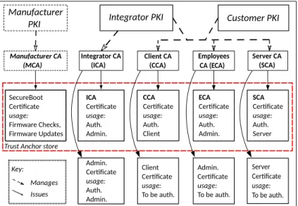
Keys and Certificates. Figure4 summarizes the global organization of the PKIs, CAs and certificates. The client and the server are shown in Figure1. We suppose here that three PKIs are deployed, but depending on the setting some of them can be merged. The right and left hatches communicate with two distinct PKIs, managed respectively by a CCA (Client CA) and a SCA (Server CA). The third PKI, for the device administration is managed by an ICA (Integrator CA) at first, and subsequently by an ECA (Employees CA). This PKI is used by the device to authenticate users for administrative tasks. In a different PKI setup, all CAs could be seen as sub-CAs of a root CA associated to the customer PKI. Modifying this store contents requires to be connected to the device as an administrator.
Integrator CA (ICA) Manufacturer CA (MCA) ICA Cer�ficate usage: Auth. Admin. Client CA (CCA) Server CA (SCA) Customer PKI CCA Cer�ficate usage: Auth. Client SecureBoot Cer�ficate usage: Firmware Checks, Firmware Updates ECA Cer�ficate usage: Auth. Admin. Employees CA (ECA) Client Cer�ficate usage: To be auth. Server Cer�ficate usage: To be auth. Admin. Cer�ficate usage: To be auth. Integrator PKI Manufacturer PKI
Trust Anchor store Key: Manages Issues Admin. Cer�ficate usage: Auth. Admin. SCA Cer�ficate usage: Auth. Server
Figure 4: Overview of the PKIs, CAs and Certificates
From the manufacturer point of view, a key pair is used in order to sign the different firmwares like the kernel or the OS along with their eventual updates. The public key and the associated SecureBoot Certificate must be installed during the manufacturing process, in order to allow the device to boot correctly.
Eventually, this certificate can become a trusted orphan, i.e., there is no concrete associated PKI (which is represented as the dotted frame on Figure4). This means that
software, from the firmware to the OS is signed and ciphered. Therefore, its integrity is preserved (cf property INT.1), and only trusted entities are able to update it. An example of secure boot is described in Section3.1.
Finally, the integrator provides one key pair, allowing an administrator to connect himself on the device. The administrator, and more generally trusted people, are au-thenticated on the device using a two factor authentication. A common implementa-tion is to use certificates located on a smart-card (see Secimplementa-tion4.2for a more detailed explanation). This means that a key pair has been previously generated and certified before being stored into the smart-card. The certificate of the ICA is installed into the device trust anchor store. The integrator might provide a complete PKI to the customer. In this case, it is in charge of certifying all keys using a dedicated CA, and adding the CA certificate into the store.
In the case where the customer has its own PKI, it must add the different CAs certificates into the store. In particular, the ones from the clients and servers the device is linked to. Moreover, it should add the CA certificate of the PKI used to deliver the trust employees’ key pair, in order to allow them to be authenticated by the device. The customer should also generate key pairs for the different applications of the device, e.g., one key pair for OPC-UA, another one for SFTP, etc. A more specific key scheme could be employed, by associating a key pair to an IP address. Each key must be certified by the CCA or the CSA in order to allow the device to be authenticated by other network devices. Finally, a symmetric key could be generated and stored into the HSM in order to cipher configuration files (property CON.2). Indeed, since the customer has the possibility to define a specific configuration depending on its network constraints, it also has the possibility to perform backups. By security, the device should output ciphered files. Finally, the configuration files integrity (cf. INT.2) can be ensured via classical cryptographic integrity mechanisms such as HMAC.
4.2 Life Cycle of keys and certificates
Here, we describe the life cycle of the device, from its integration into the customer network to its administration.
Integration process.Once the device has booted correctly for the first time, it must be initialized to accept external connections, both from clients and servers and from administrators. The latter use a two factors authentication system, using smart cards in the manner of credit cards (cf. AUT.2). First, the administrator proves his card own-ership by entering his PIN code on a keyboard linked to the device. Then, the card is authenticated by the device using certificate based authentication. Therefore, certifi-cates of its associated CA must have been previously included within the device trust anchor. This means that the manufacturer provides the first boot administrator smart cards and that those have been signed by their dedicated CA. Once the administrator is connected to the device, he has the possibility to add new CA certificates into the trust anchor store. First, he adds the manufacturer CA. This allows people using certificates that have been issued from this CA to be authenticated by the device. Second, the ad-ministrator supplements the store with the CA certificates used to distribute clients and servers certificates. In the case of two distinct PKIs, the client and the server might have two different CAs, and so different certificates must be included. The device is then able to accept connections.
Production. During the production phase, the device could need to generate new key pairs. There are two possibilities: either the device generates them, or key pairs are added by the administrator. In the first case, once the key pair has been generated, the device generates the associated ToBeSigned form of X.509 certificates. This is transmitted to the CA, which signs it. Then, the certificate should be added to the trust anchor store in order to be used by the device. The other possibility is that the CA generates both the key pair and the associated certificate, and then an administrator puts both of them into the HSM.
Administration.Administration of the device includes different kind of tasks. First, it should regularly be updated to prevent attacks. These updates could be performed by a device administrator (using a certificate issued by the customer, manufacturer or integrator CA). However, the update files should be signed by the manufacturer to en-sure their integrity. Since the device has the associated certificate, it can check the signature. Moreover, the trust anchor store content should be managed: generation or revocation of key pairs and certificates, addition of new CAs (with the inclusion of their certificates). Depending on the situation, the device could employ the Online Cer-tificate Status Protocol(OCSP) (evenOCSP Pinning, to save communications) along with Certificate Revocation Lists (CRL) and ∆-CRLs. The first two options are recom-mended if an OCSP responder is deployed in the network, whereas CRL are applicable without any online interaction. However, it requires that an administrator updates them following the customer’s PKI Certification Practice Statement and Certification Policy. This implements the property AUT.1. Finally, the device embeds dedicated configura-tions related to the filtering parts. This part could be delegated to a sub-administrator: this means that a trust person is able to modify configuration files but cannot change security parameters.
5
Protocols Splitting and Filtering
In this Section, we explain how we perform protocol splitting and filtering of the mes-sages.
5.1 Protocols Splitting
Part of the network isolation is provided by the splitting action applied on each pro-tocol stream received by the device. The idea is to rewrite each message in a common generic language: information contained into the meta-data along with message con-tent must be extracted. This step is called deconstruction. In the end, all protocols are transformed into this generic language which can be filtered. Benefits of this approach are twofold. First, since the filtering is performed on the intermediate representation after deconstruction, one can change the protocols used by the system while keeping the rules of the filter. Secondly, this offers the possibility to transform a protocol into another one.
To perform the deconstruction, there is a server for each protocol implemented on a hatch of the device. This server has the responsibility to transform each received message into the intermediate representation. We target protocols where commands allow a client to read and write variables on a server. This is very common in the case
of industrial protocols but can also be applied to other domains. For instance, SFTP directly implements READ and WRITE on files and those can also be seen as variables. The information included in the intermediate form are the following:
• Time of emission if provided and time of reception by the device, • Service (read/write/subscribe) and path (request/response),
• For each variable targeted by the command: the dimensions of the variable (for arrays, matrix, etc.); the targeted range (to only target parts of arrays, matrix); the values (new values for write request, values read in read responses).
5.2 Stream Analysis
As mentioned in Section5.1, we take advantage of the fact that a protocol splitting device is tailored to filter READ and WRITE requests on variables. In this context, we propose different types of rules for the filter which aim to ensure access permission control on the variables through deep packet inspection.
1. Ensure that only explicitly authorized protocols (TLS, SFTP or OPC-UA) and ser-vices (READ, WRITE) will pass through the device. This allows for instance to con-figure the device to be read-only for all requests (all write requests would be rejected). 2. Ensure that only explicitly authorized peers will communicate together. This clas-sical firewall property enforces a client to only communicate with servers it is allowed to. As mentioned earlier, authentication of clients and servers can be based on IP ad-dresses, ports or cryptographic keys when available. Also depending on the context it can be possible to authenticate users on clients (e.g., using a secure token).
3. Enforce access control of clients on server variables. This allows a client to only access a subset of the variables on the server. For instance, a client with lower access rights could only access non-critical variables while an administrator would access all. 4. Enforce permissions control of clients on server variables. This allows a client to only make a certain type of requests (e.g., only read) while other clients could write. This property differs from property1in the fact that it is specific to each client and not global to the device. It would also allow to specify read-only variables for all clients while other variables could be written.
5. Maintain global properties on the state of the system. To achieve this, the filter keeps a copy of certain variables as they go through it. Those make it possible for the user to specify safety properties using propositional logic predicates (over Boolean or integers) such as ”The furnace should not start if the door is open”. One can argue that the filter can only have a local vision of the variable and their value can have changed since the last time they appeared in a message. However, since the filter is supposed to be the single point of passage for all messages, the vision of the filter is at least the same as the client. Moreover, we will show in Section6.2how we can deal with unknown or old values.
To make a judgment, the filter has three primitives: (1) ACCEPT, (2) REJECT and (3) LOG. For each request, it verifies the rules one by one in the order of they appear. 1. In case of ACCEPT, the request is accepted without verifying the next rules (it is a ”force accept”). This primitive is useful to white-list some special cases that would be blocked by later rules.
3. In case of LOG or in absence of judgment, the filters evaluates the next rules. Finally the filter reaches the end of all rules without a REJECT, the request is accepted. Algorithm 1 Evaluation of messages by the filter
Require: RU LES is the set of rules configured on the filter. Return: True if the whole message is accepted, False otherwise.
1: functionEVALMESSAGE(msg = [req1, .., reqn])
2: for all req ∈ msg do
3: for all rule ∈ RU LES do
4: judgment ←EVALRULE(req, rule)
5: if judgment = REJ ECT then
6: return False
7: else if judgment = ACCEP T then break
8: return True
However depending on the protocol (e.g., OPC-UA), a message can be a sequence of requests (e.g., READ(var1, var2, var3)). To implement security feature ROB.2, we propose a sequential evaluation of rules in the general case in Algorithm1. One will note that in absence of ACCEPT, the filter will check the next request of the message if any. Conversely, in case of REJECT, the filter will reject the whole message without looking at other requests, if any, and independently of those being accepted. Thus, rejects have priority over acceptations.
6
Security Guarantees Provided
In this Section, we perform a security analysis of the solution we propose to show that the protocol splitting device respects the security requirements presented in Section2.2. 6.1 Improvements by Splitting Protocols
Splitting protocols adds security in the sense that messages are deconstructed and reconstructed in a safe environment. Thus all possible network attacks on the stack before the applicative level will not go through the device (e.g., malformed packets, ping of death, etc.). Malformed packets will be refused by the servers on the hatches, thus implementing security feature ROB.3. Moreover, at the applicative level we guar-antee that only a controlled subset of all possible commands of each protocol is going through the device. This is done by design when translating each message in the in-termediate representation. If a message cannot be translated, then it is refused. Thus for instance if we choose to not implement a “Delete” command at the intermediate level, then the DELE and RMD commands from SFTP will be blocked, preventing the clients from deleting files and directories.
6.2 Improvements by Filtering
The filter obviously adds some security via its function blocking messages tagged dangerous (when writing the rules). Moreover, it is designed to be robust and to resist to unexpected events such as malformed messages or rules.
Bounded execution. As detailed in [16], the filter is able to evaluate rules on a message in bounded time and memory. Every operator that can be used in a rule allows verification of a message in constant time. Thus if we associate a constant processing time τito each predicate Piappearing nitimes total in all the rules, we can compute
the worst case processing time T of a request as: T =P τini.
Three-valued logic. As the filter maintains a local view of certain specified vari-ables to enforce global safety properties on the system, it can happen that a rule requires the value of a variable that have never been seen or that is too old. In this situation, no decision can be taken. For this sake, we use a three valued logic such as Kleene’s logic [13]. Three valued logic introduce a value neither True nor False, called Unknownor Irrelevant and extend classic logic operators to handle such a value. Thus the filter may answer to a message: that it does not know if it should accept it or not (a default policy is thus needed).
Configuration Check. The main problem with any filter is to allow users to ex-press the rules they have in mind. The most secure filter has no purpose if it is badly configured. Obviously, malformed configuration files are rejected as they can have a misleading behavior or even break the filter. Rejecting them implements security fea-ture ROB.1. However if rules are correctly formed, they still can be in conflict with each other. Thus, to prevent inconsistent rules configuration that would for example block all messages, we propose some consistency checks. They verify for instance that all permission on clients, servers and variables are compatible with each other (for instance, if a variable is read only then no client should be authorized to overwrite it).
7
Conclusion and Future Work
In this paper, we have presented a security device for industrial networks. It provides security by isolating the left and right sides of the device, which are seen as separated networks. It validates all security requirements of classical firewall protection profiles but also isolation requirements such as memory, peripheral and computations isolation as well as network segregation, bridging the gap between firewalls and diodes. The results presented here are the result of thearamis.minalogic.netR&D project and will be partly found in Secl¯ab products in the near future. Compared to a firewall we provide isolation (attacking the first hatch does not allow to bypass the filters). Compared to a diode we allow to observe the industrial process while preventing an attacker to modify its behaviour, moreover, contrary to a diode, periodical polling of variable values is not needed. In the future, we also plan to support more protocols within the device and, in addition to our security analysis, an emulation of the device could go through a SCADA security testbed such as [11]. For each protocol we would add, we need to provide a way to convert it into the intermediate language representation. We also consider to generalize the use of the device. Currently, its purpose is to separate zones with different security levels. However, it could also be used as a secure gateway between two zones (or even as a standalone VPN), connected with an insecure protocol, while still applying protocol splitting and filtering on the messages. This way we can also provide security even when the used protocols do not.
References
[1] Managing cybersecurity for industrial control systems. Agence nationale de la
s´ecurit´e des syst`emes d’information (ANSSI), June 2012.
[2] Protection profile of an industrial firewall. ANSSI, July 2015.
[3] M. J. Assante and R. M. Lee. The industrial control system cyber kill chain. SANS, Oct. 2015.
[4] A. Aziz. The evolution of cyber attacks and next generation threat protection. In RSA Conference, 2013.
[5] S. Blanch-Torn´e, F. Cores, and R. M. Chiral. Agent-based PKI for distributed
control system. In WCICSS’15, pages 28–35, Dec. 2015.
[6] E. Byres, J. Karsch, and J. Carter. NISCC good practice guide on firewall
de-ployment for SCADA and process control networks. Technical report, National
Infrastructure Security Co-Ordination Centre, 2005.
[7] Y. Cherdantseva, P. Burnap, A. Blyth, P. Eden, K. Jones, H. Soulsby, and K. Stod-dart. A review of cyber security risk assessment methods for SCADA systems. Computers & Security, 56:1 – 27, 2015.
[8] Firewall protection profile v2.0. Common Criteria, Apr. 2008.
[9] M.-A. Cornelie.Implementations and protections of software and hardware
cryp-tographic mechanisms. Phd, U. Grenoble Alpes, 2016.
[10] E. Cosman, editor.Security for industrial automation and control systems -
Mod-els and Concepts. Int. Society of Automaton, 2017.
[11] A. Ghaleb, S. Zhioua, and A. Almulhem. SCADA-SST: a SCADA security
testbed. In WCICSS’16, pages 1–6, Dec 2016.
[12] L. Jacquin. Performance/security trade-off for high-bandwidth Internet VPN
gateways. Phd, Universit´e de Grenoble, Nov. 2013.
[13] S. C. Kleene. Introduction to metamathematics. Ishi Press, 1952.
[14] G. Klein, K. Elphinstone, G. Heiser, J. Andronick, D. Cock, P. Derrin, D. Elka-duwe, K. Engelhardt, R. Kolanski, M. Norrish, T. Sewell, H. Tuch, and S. Win-wood. seL4: Formal verification of an OS kernel. In ACM SIGOPS’09, pages 207–220, 2009.
[15] J. Pescatore and G. Young. Defining the next-generation firewall. Technical report, Gartner RAS Core Research Note, 2009.
[16] M. Puys, J. Roch, and M. Potet.Domain specific stateful filtering with worst-case
[17] P. Rouget, B. Badrignans, P. Benoit, and L. Torres. SecBoot: lightweight secure
boot mechanism for linux-based embedded systems on FPGAs. In ReCoSoC’17,
pages 1–5, July 2017.
[18] C. Shepherd, G. Arfaoui, I. Gurulian, R. P. Lee, K. Markantonakis, R. N. Akram, D. Sauveron, and E. Conchon.Secure and trusted execution: Past, present, and fu-ture: Critical review in the context of the internet of things and cyber-physical sys-tems. In IEEE Trustcom/BigDataSE/ISPA, Tianjin, China, August 23-26, 2016, pages 168–177, 2016.
[19] K. Stouffer, J. Falco, and S. Karen. Guide to industrial control systems (ICS)
security. NIST special publication, 800-82, May 2013.
[20] S. Thomason. Improving network security: next generation firewalls and
ad-vanced packet inspection devices. Global Journal of Computer Science and
Tech-nology, 2012.
[21] S. M. Trimberger and J. J. Moore. FPGA security: Motivations, features, and
applications. Proceedings of the IEEE, 102(8):1248–1265, 2014.
[22] W. Wang and Z. Lu. Cyber security in the smart grid: Survey and challenges. Computer Networks, 57(5):1344–1371, 2013.
[23] S. Zapechnikov, N. Miloslavskaya, and A. Tolstoy. Modeling of next-generation
firewalls as queueing services. In 8th Int. Conf. on Security of Information and