HAL Id: insu-02270094
https://hal-insu.archives-ouvertes.fr/insu-02270094
Submitted on 23 Aug 2019
HAL is a multi-disciplinary open access
archive for the deposit and dissemination of sci-entific research documents, whether they are pub-lished or not. The documents may come from teaching and research institutions in France or abroad, or from public or private research centers.
L’archive ouverte pluridisciplinaire HAL, est destinée au dépôt et à la diffusion de documents scientifiques de niveau recherche, publiés ou non, émanant des établissements d’enseignement et de recherche français ou étrangers, des laboratoires publics ou privés.
Engine management software dynamic architecture
versus integration
Denis Claraz, Michael Niemetz
To cite this version:
Denis Claraz, Michael Niemetz. Engine management software dynamic architecture versus integration. Embedded Real Time Software and Systems (ERTS2008), Jan 2008, toulouse, France. �insu-02270094�
Engine management software dynamic architecture versus
integration
D. Claraz
1, M. Niemetz
21: Continental Automotive France SAS, 1, av. Paul Ourliac, BP 1149, Toulouse - France 2: Continental Automotive Germany AG, Siemensstr.12, Regensburg - Germany
Abstract
Variability, hard real time, increasing functional complexity (due to emissions and driveability standards), limited hardware (HW) resources : these are some of the – sometimes antagonistic – constraints a modern Engine Management Software (EMS) has to deal with. In addition, to face the price reductions in the automotive electronics industry, an intensive reuse strategy is deployed, based on a platform architecture and a component based development, despite the high functional coupling between those components, characteristic to the engine management area.
Fig. 1: Memory vs. price of EMS
To respond to these constraints, a static (or functional) architecture defines the split of the software (SW) into compilation units: modules or aggregations of modules. This static architecture mostly focuses on reuse and decoupling of functions. It is in general well managed, documented, and supported by tools.
In parallel to this static facet, to respond to the real time requirements, the dynamic architecture defines the split of the SW into execution units: functions, tasks, interruptions. This part of the architecture is often underestimated, poorly documented, and insufficiently supported by tools.
This dynamic facet is characterized by sporadic events, time events in a range of 1 millisecond (ms) to 1 second (s), and angular events in a range of 0.5ms to 100ms depending on engine configuration and speed. The EMS functions have to be called
from these events, and in addition to their recurrence, they may have phasing, sequencing, and also deadline constraints.
Typical problems in the dynamic behavior are infinite loops, wrong initializations of pointers, stack overflows, recursivity, wrong calculation sequences, data inconsistencies, and deadline misses. Whereas some of these errors are intrinsic to SW-components (SW-C), others are related to their integration within the project. In other words, the same SW-C may show a correct behavior in one project, but an incorrect behavior in another project, because of integration failure, or different integration contexts. After an overall description of the EMS context, we will describe in this paper the most common integration failures with impact on dynamic behavior, and means to avoid them. We will also show the importance of the architecture and integration activities in the specific area of engine management, in particular due to the above mentioned constraint of strong coupling.
Keywords: engine management, real time,
integration, dynamic architecture, scheduling, data consistency.
1. Context of Engine Management Software
A high end Electronic Control Unit (ECU) may have up to 200 connectors, 250.000 lines of code, and around 1000 functions to control all sensors and actuators needed to manage the combustion process of the engine.
Fig. 2: Gasoline direct injection system
The architecture of the software is mostly impacted by the following constraints:
Coupling between EMS functions:
An EMS is a system with a high functional cohesion. There are only few functions mapped to an EMS, which could be exported to another ECU of the vehicle. These functions interact together either directly or through the engine and the components they control, and thus can hardly be managed independently.
Fig. 3: All sensors and actuators managed by EMS are involved in the same physical process For instance, misfire, injection and ignition functions depend on each other and participate all to the same combustion process. They are interacting together, and thus communicate by exchanging data. In the following figure, we give an overview of the coupling
of the main EMS functions on a typical high end project.
Fig. 4: Coupling between main EMS functions On this graphic, each dot represents interfaces (links) between the functions. In particular, we see that there is nearly no 1:1 link between functions, and that most of the functions are linked to many other ones. To be more concrete, typical variables of the system like engine speed, coolant temperature, ignition key, ... are needed in more than 100 modules, spread in around 50 functions.
This strong coupling between functions creates one of the most important constraints on the architecture, and is specific to Engine Management Systems.
Variability:
Due to the reuse objectives, the configurability of the EMS SW is a key issue, in order to avoid parallel branches, expensive to maintain. EMS applications are similar, but have also a big level of variability, due to different engine architectures, sensor and actuator positions or electrical characteristics. This variability is much higher at the supplier side than the OEM side, due to a customer and multi-engine orientation.
As an example, the figure below shows the diversity of camshaft target profiles that have to be handled by the same SW.
ERRM INSY EGCP ENSD CHRG THRO VVLI LACO ECM2 ENTE VVTI EVAC INJR TQDR FMSP TQSP EGTR MISF ENSC EVAM ECM3 FUSL AIRT EXTC ENSS EXTD KNCK ALAM DRVB IGRE ENRD FUTL DRRQ IGSP TQLO ENSL EGPR AEFP LASP AVIM EGCP 250 12 490 5 0 11 3 14 0 3 2 5 2 1 0 1 13 3 0 1 0 2 0 1 1 3 0 6 0 1 0 0 0 0 0 0 0 0 0 0 INSY 80 337 0 6 15 17 11 7 0 2 2 3 0 1 2 1 1 0 0 1 0 1 0 0 1 0 0 0 0 0 0 0 0 0 0 0 0 2 0 1 CHRG 80 28 0 5 298 9 0 0 0 1 0 0 1 1 1 4 0 0 0 0 0 0 0 2 1 1 0 0 0 0 0 0 0 0 0 0 0 0 0 0 ERRM 243 31 21 6 5 11 8 16 2 11 6 4 1 2 1 0 3 6 3 2 0 8 5 0 3 5 2 2 0 1 1 0 2 0 1 0 0 2 0 0 EGTR 240 10 14 4 0 11 1 11 0 3 2 3 2 0 0 0 101 3 0 1 0 1 0 1 1 2 0 0 0 1 0 0 0 0 0 0 0 0 0 0 VVLI 43 9 2 10 0 0 200 5 0 1 7 1 0 5 0 1 0 1 1 0 0 0 0 1 2 0 0 0 1 0 4 0 0 0 0 0 0 0 0 0 ECM2 6 3 1 4 0 11 1 3 190 3 2 0 6 5 11 4 0 0 16 1 18 2 0 0 0 0 0 0 0 1 0 0 0 0 0 0 0 0 0 0 EVAM 144 12 0 2 0 8 2 3 0 2 2 5 1 0 0 0 0 0 2 101 0 0 0 1 1 0 0 0 0 1 0 0 0 0 0 0 0 0 0 0 ENSD 40 0 0 208 0 0 0 0 0 0 4 0 0 0 0 0 0 0 0 0 0 0 0 0 0 0 0 0 0 0 0 0 0 0 0 0 0 0 0 0 LACO 11 12 16 6 0 3 1 164 0 3 3 9 3 0 2 0 5 3 0 4 0 1 0 1 1 1 0 1 0 1 0 0 0 0 0 0 0 0 0 0 VVTI 28 4 0 6 0 8 7 0 0 2 165 0 0 3 0 1 0 0 0 0 0 0 0 1 0 0 1 0 1 0 0 0 0 0 0 0 0 0 0 1 ENSC 72 6 0 8 0 13 0 2 0 3 2 1 0 0 1 3 1 0 86 1 0 0 0 3 1 0 0 1 2 1 0 0 0 0 0 0 0 0 0 0 AIRT 67 12 0 5 4 0 4 0 0 4 0 0 0 0 0 1 0 0 0 0 0 0 105 0 3 0 0 0 0 0 0 0 0 0 0 0 0 0 0 0 EVAC 4 9 5 3 0 2 0 12 0 2 2 141 2 2 4 1 1 1 0 6 0 3 0 0 1 0 0 0 0 1 0 0 0 0 0 0 0 0 0 0 THRO 19 7 0 2 0 162 2 0 1 2 0 0 0 1 0 0 0 0 0 0 4 0 0 0 0 0 0 0 0 0 0 0 0 0 0 0 0 0 0 0 INJR 6 2 0 10 0 1 5 0 1 2 0 0 126 1 17 1 1 2 0 0 5 2 0 4 6 0 0 2 2 1 0 0 0 0 1 0 0 0 0 0 TQSP 6 3 0 3 1 5 4 0 5 2 0 1 1 27 1 85 0 0 9 0 0 5 0 7 1 1 1 0 7 0 0 0 0 0 1 1 0 0 0 0 ENTE 41 9 0 4 0 0 0 0 0 115 0 0 0 0 0 1 0 0 0 1 0 0 3 0 3 0 0 0 0 0 0 0 0 0 0 0 0 0 0 0 FMSP 0 9 0 6 0 2 8 3 0 4 1 0 6 1 103 2 0 0 1 1 0 3 0 6 10 0 0 0 0 1 0 0 0 0 1 0 0 0 0 0 MISF 23 3 2 6 0 4 2 0 0 2 1 0 5 3 0 0 0 96 0 1 0 0 0 1 1 1 0 0 0 3 8 0 0 0 0 0 0 0 0 0 FUSL 21 0 2 4 0 0 1 6 0 4 0 2 3 1 2 2 1 2 0 2 0 87 0 5 7 0 0 0 0 0 0 0 0 0 0 0 0 1 0 0 TQDR 0 9 0 4 0 1 3 0 0 2 0 0 2 91 0 14 0 0 4 0 0 0 0 1 0 0 1 0 0 1 0 0 0 1 1 0 0 0 0 0 KNCK 22 4 0 8 0 3 1 0 0 2 0 0 1 0 0 0 0 0 0 0 0 0 0 0 1 0 86 0 1 1 0 0 0 0 0 0 0 0 0 0 EXTD 23 2 2 1 1 0 1 0 0 4 0 0 2 1 2 0 1 0 0 0 0 0 0 0 2 83 0 0 0 0 0 0 0 0 0 0 0 0 0 0 EXTC 1 8 0 4 1 3 1 2 0 3 2 0 2 3 2 4 1 1 0 1 0 1 0 72 1 5 0 0 1 1 0 0 0 0 0 0 0 0 0 0 ALAM 1 2 4 3 0 0 0 16 0 1 2 2 1 0 0 1 0 2 0 0 0 0 0 2 0 1 0 67 0 0 0 0 0 0 0 0 0 0 0 0 ECM3 4 0 0 0 0 0 0 0 5 0 0 0 0 0 0 0 0 0 0 0 95 0 0 0 0 0 0 0 0 0 0 0 0 0 0 0 0 0 0 0 IGRE 27 2 0 9 0 1 0 0 0 1 0 0 1 0 0 1 0 1 0 0 0 0 0 0 2 0 0 0 0 55 0 0 0 0 0 0 0 0 0 0 DRVB 0 0 0 4 0 0 1 0 0 1 0 0 1 1 0 4 0 0 3 0 0 0 0 0 0 0 0 0 61 0 0 0 0 0 0 0 0 0 0 0 ENRD 8 2 0 9 0 4 0 0 0 1 0 0 1 0 0 0 0 4 0 1 0 0 0 0 0 0 0 0 0 0 39 0 0 0 0 0 0 0 0 0 ENSS 6 0 0 3 0 0 0 0 0 2 0 0 2 0 1 0 1 0 0 0 0 1 0 0 48 0 0 0 0 0 0 0 0 0 0 0 0 0 0 0 IGSP 0 3 0 3 0 0 9 0 0 1 0 0 0 3 4 1 0 0 0 0 0 0 0 1 3 0 1 0 0 0 0 0 0 24 0 0 0 0 0 0 DRRQ 16 0 0 2 0 0 0 0 1 0 0 0 0 2 0 0 0 0 0 0 0 0 0 0 0 0 0 0 0 0 0 0 31 0 0 0 0 0 0 0 FUTL 8 0 0 1 0 0 0 0 0 0 0 0 0 1 1 0 0 0 0 0 0 0 0 0 0 0 0 0 0 0 0 35 0 0 0 0 0 0 0 0 TQLO 1 4 0 2 0 2 2 2 1 4 2 0 1 0 1 0 0 1 3 1 0 1 0 0 0 0 0 0 0 1 0 0 0 0 15 0 0 0 0 0 ENSL 0 0 0 5 0 3 1 0 2 1 0 0 0 1 0 0 0 0 0 0 0 0 0 0 0 0 0 0 1 0 0 0 0 0 0 11 0 0 0 0 LASP 0 1 2 1 0 0 0 0 0 2 0 0 0 3 0 1 2 0 0 0 0 0 0 4 0 0 0 0 0 0 0 0 0 0 0 0 0 0 7 0 AVIM 6 3 0 3 0 0 0 0 0 1 0 0 0 1 0 1 0 0 0 0 0 0 0 0 1 0 0 0 0 0 0 0 0 0 0 0 0 0 0 3 EGPR 0 3 0 1 4 0 0 0 0 0 0 0 0 0 1 0 0 0 0 0 0 0 0 0 0 0 0 0 0 0 0 0 0 0 0 0 9 0 0 0 AEFP 7 0 0 2 0 0 0 0 0 2 0 0 0 0 0 0 0 0 0 0 0 1 0 0 1 0 0 0 0 0 0 0 0 0 0 0 0 0 0 0 > 10 6...10 < 6 Number of links 40 functions export... 40 functions import ... Fct_04 Fct_02 Fct_01 Fct_09 Fct_03 Fct_15 Fct_06 Fct_10 Fct_41 Fct_1 8 Fct_11 Fct_14 Fct_16 Fct_22 Fct_19 Fct_17 Fct_05 Fct_20 Fct_12 Fct_08 Fct_27 Fct_21 Fct_13 Fct_25 Fct_31 Fct_24 Fct_23 Fct_26 Fct_29 Fct_28 Fct_30 Fct_34 Fct_33 Fct_32 Fct_35 Fct_36 Fct_39 Fct_40 Fct_37 Fct_38 Fct_01 Fct_02 Fct_03 Fct_04 Fct_05 Fct_06 Fct_07 Fct_08 Fct_09 Fct_10 Fct_11 Fct_12 Fct_13 Fct_14 Fct_15 Fct_16 Fct_17 Fct_18 Fct_19 Fct_20 Fct_21 Fct_22 Fct_23 Fct_24 Fct_25 Fct_26 Fct_27 Fct_28 Fct_29 Fct_30 Fct_31 Fct_32 Fct_33 Fct_34 Fct_35 Fct_36 Fct_37 Fct_38 Fct_39 Fct_40 Composite Manifold Active Carbon Caniste Canister Purge Solenoid Fuel Supply Unit High Pressure Fuel Pump with Flow Control Valve Fuel Pressure Sensor NOx Linear / Binary O2 Sensor Mass Air Flow
Sensor with Integrated Temp. Sensor Exhaust T e Dual Cont. Var. Cam Phaser Electronic Throttle Control Exhaust Gas Recirculation Valve (EGR) Air Cleaner Box
3-Way Catalyst Lean NOx
Trap Catalyst Camshaft Position Sensor Active Crankshaft Position Sensor Engine Coolant Temperature Sensor Knock Sensor Manifold Absolute Pressure Sensor Piezo Direct Injection Piezo Injector Ignition Engine Control
Fig. 5: Same SW for different camshaft targets In total, more than 160 points of configuration are needed to configure the acquisition of engine position and speed, depending on the shape of the crankshaft, the type and position of sensors, the type of diagnosis, etc... For a complete application, more than 10.000 points of configuration are used.
Real time:
As the physical process in a combustion engine is fast and repetitive, an EMS is a fast system: Acquisitions, diagnosis, treatments, and corrections on control strategies are done very often. To reach new emission regulations, new functionalities require multiple acquisitions of the same parameter and multiple actuations of the same output within one same combustion cycle. Engine synchronous calculations may have a recurrence of 2.5 ms on 8 cylinder systems, and fast time bases like 5 ms are widely used. As a result, around 80% of the calculations are executed within a 10ms (or faster) time frame.
Fig. 6: Relative weight of main recurrences In addition to this speed, the complexity of an EMS is due to the mixture between sporadic events (like for instance an ignition key transition), time periodic events, and angle periodic events. For instance, many calculations are synchronous to the crankshaft position. Their recurrence is variable, and can range from 100ms at low engine speed to 5ms at high engine speed, for a 4 cylinders engine. In total,
around 70 different events are needed with sometimes precise phasing or deadlines needs.
Fig. 7: Time and Angle based events
Reuse:
As mentioned, reuse is a key driver of the architecture, in order to reach productivity objectives inherent to the automotive electronics industry. This reuse impacts mostly the static architecture, i.e. the split into functional bricks. The decoupling of functionalities is done using a top-down approach and an aggregate concept already described in ERTS2004 [1]. This is done through a better and formalized management of interfaces, and through an application of abstraction principle, in order to define sub-packages (aggregates) with a high internal coherency.
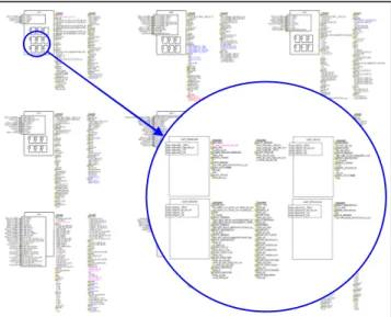
Fig. 8: Hierarchical architecture: packages of SW-Cs (Hood-like representation)
Finally, a hierarchical architecture is defined, with different levels of interfaces.
Camshaft Position Sensor TDC 5 ms 10 ms 100 ms 1000 ms 60 % 50 % 40 % 30 % 20 % 10 % 0 % % of ROM size Project A 80% of SW every 10ms
Project B Project C Project D
Cam
shaft CAM CAM
Crank shaft GAP TDC TDC Angular Events 1 ms 5 ms 10 ms 1000 ms 100 ms Time Events
Hardware resources:
In order to minimize the ECU price, the RAM, ROM and CPU load consumptions have to be limited. The balance has to be done between the economy of
HW resources and the typical objectives of
maintainability, testability, and in particular reusability. In the simple example shown below, a calculation done every top dead center (tdc) depends on interpolations on input variables with different dynamics. Some of them change every tdc, but some other only every 100ms or every 1s. To ease the integration (testability and maintainability) of such a function, a monolithic calculation every tdc would be the best choice. But this would cost approximately twice the CPU load as a calculation optimized according to the input variables dynamics.
Fig. 9: CPU load vs. dynamic architecture
On the other side, the non monolithic solution would be the most efficient in term of CPU load, but would be more expensive in term of RAM and ROM consumption.
Business model:
With the introduction of OSEK in 2001, a fundamental change of the business process has been initiated: before that date, the complete SW embedded in the ECU was developed by the supplier (based on own, or on OEM specifications). Today, a complete project is – and will be more and more – built from individual SW-C coming from the
OEMs, suppliers, tool vendors, and even
competitors. The formats of the SW-C to be integrated are disparate (C, obj, libraries, MDL, XML), and have increasing impact on the architecture. For instance, a non-negligible part of the CPU, RAM, ROM is dedicated to interface adaptation.
2. Different views on an EMS architecture
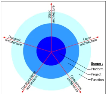
According to the above constraints, the EMS architecture is split into different facets (or areas), corresponding to different types of problems. Architectural choices and mechanisms are defined in each of these areas, and may apply either to a complete platform (or product line, or project family), to a single project, or finally to a single function.
Fig. 10: Facets and scope of architecture
The Static architecture , or functional architecture,
aims to split the system into functional abstractions, with an objective of decoupling functionalities. These functional abstractions will be either modules (i.e. compilation units, SW-Cs), or groups of SW-Cs. These SW-Cs will be the base for reuse, or for
distributed development1.
Typical topics of static architecture are:
- In which SW-C to locate the torque correction
due to air conditioning?
- Is it possible to exchange calibration data
between SW-Cs? Which kind of exchange is allowed? Why?
Fig. 11: Static (or functional) architecture of EMS
The Layer architecture defines the split into
hardware abstractions, with an objective of independence from microcontroller, hardware, or
1 With increasing size and complexity of applications, a good partitioning is becoming essential to reduce coupling, allow work split between teams, and ease further integration.
var = interpolation (v,w) + interpolation (x,y) * interpolation (z)
tdc 100 ms tdc tdc tdc 1 sec
CPU Load at 6000 rpm:
Calculation at each tdc =0.12 %
Calculation split in tdc, 100ms and 1s =0.06 %
Factor = 2
Engine states Fuel Engine cooling & lubrication
Electric power Torque Ignition Engine
Position & Speed
Body & interior Basic ECU functions Combustion process Air Exhaust gas Electric drive Transmission Chassis System manager Vehicle Powertrain
Engine - Gasoline or Diesel
Transverse Functions Vehicle Motion Powertrain Management Communicati on
harness. The constraints of reuse, efficiency, hard real time, etc... may be different in different layers, leading to different architecture rules.
Fig. 12: Functional architecture plugged on layer architecture of EMS
Typical topics of layer architecture are:
- In which layer to locate the ignition dwell
control?
- How to exchange information between layers?
The "Operational" (logistical) architecture defines
the mechanisms used in all SW-Cs and applications, with an objective of standardization of implementation. Similar problems have to be treated in a consistent way, when they appear in different SW-Cs or projects.
Some examples of such choices are:
- Which data type to use for a temperature?
- Which mechanism for data exchange between
SW-Cs, which include structure? Which use of floating point? Which memory allocation?
The "Configurational" architecture focuses on the
management of the variability, with an objective of reducing its impact on development effort and hardware resources. Once integrated in a project, a SW-C designed to be "configurable" will then become "configured". This configuration can be done either at "build time" (same source code, different executables), at "runtime" (same source code, same executable, different parameters), or both.
Examples of topics related to this facet are:
- How to decouple the ignition functionality from
the number of cylinders?
- How to encapsulate the diversity? How to handle
its impact on the interfaces?
The Dynamic architecture, finally, aims to split the
system into execution units (i.e. tasks), with an objective of schedulability and efficiency. This facet is described in the following chapter.
3. Dynamic architecture of an EMS
As described before, an EMS is stimulated by around 70 sporadic, periodic, or angular events, mostly represented by Operating System tasks. The phasing between these events is sometimes important, and for one same recurrence, there might be different events with different phasing. For instance, in order to be precise in the combustion cycle, different events are necessary between 2 tdc of the same cylinder. So, the first dynamic architecture choice, when designing, and integrating a control strategy, is the selection of the adequate event(s), out of a list of around 60. The below figure shows the functions split on some events and puts in focus that the EMS functions are not monolithic in term of dynamics, but use various events (for functional or HW resources optimization reasons).
Fig. 13: Functions vs. events mapping
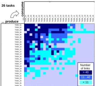
Consequently, in addition to the static data flow described in Fig. 4, a dynamic data flow can be displayed, corresponding to the exchange between events, or tasks: A variable is modified by one (or more) event, and read by one (or more) other event.
Fig. 14: Data flow (coupling) between main tasks
LIBRARIES
OSEK OPERATING SYSTEM
INFRASTRUCTURE
(HW DEPENDENT) INTERFACE FUNCTIONALITY
... consume
TASK_C0_RST TASK_C1_10MS TASK_C1_1000MS TASK_C1_100MS TASK_C1_SEG TASK_C2_10MS TASK_C1_20MS TASK_C1_HALF_SEG TASK_C2_100MS TASK_C1_COM_CAN_10MS TASK_C1_CAM_IN1 TASK_C1_40MS TASK_C1_CAM_IN2 TASK_C1_5MS TASK_C1_CRK_GAP TASK_C1_CRK_MCPS TASK_P_1MS TASK_C2_5MS TASK_EVT_INJ_EOC TSK_EVT_RX_CCP_TSK TASK_BG_MES TSK_EVT_TX_CCP_TSK TASK_C1_MON2 TASK_C1_CAM_EX1 TASK_C1_CAM_EX2 TASK_C3_10MS TASK_C1_SEG 2204 3002 927 699 0 331 502 522 218 243 111 101 111 90 124 45 10 24 12 0 0 1 0 0 0 0 TASK_C2_10MS 968 957 213 182 1377 0 157 248 200 131 90 70 90 79 89 49 14 0 11 0 0 1 0 0 0 0 TASK_C1_10MS 2026 0 787 561 8 254 132 82 132 21 38 36 38 45 32 25 7 6 5 0 0 0 1 0 0 0 TASK_C0_RST 0 95 154 187 116 285 149 90 177 38 53 59 53 49 54 39 11 12 8 6 2 1 2 1 1 1 TASK_C1_1000MS 694 61 0 103 33 57 38 24 79 6 16 21 16 14 14 13 0 0 0 0 0 0 0 0 0 0 TASK_C1_20MS 321 277 70 133 36 71 0 34 40 7 17 17 17 20 17 17 1 2 0 0 0 0 0 0 0 0 TASK_C2_100MS 183 134 59 51 158 73 29 28 0 6 7 26 7 22 7 6 0 0 0 0 2 0 0 0 0 0 TASK_C1_100MS 314 22 100 0 25 56 63 18 25 7 12 11 12 12 16 9 0 0 1 0 1 0 0 0 0 0 TASK_C1_COM_CAN_10MS 222 222 16 8 0 66 9 0 23 0 0 34 0 0 0 0 0 1 0 0 0 0 0 0 0 0 TASK_C2_5MS 130 112 5 3 117 78 3 0 10 126 0 9 0 0 0 0 0 0 0 0 0 0 0 0 0 0 TASK_C1_HALF_SEG 112 142 41 36 0 44 35 0 30 2 11 27 11 26 11 10 3 0 9 0 0 0 0 0 0 0 TASK_C1_CRK_GAP 66 77 10 14 1 8 6 7 7 1 63 2 63 3 0 1 3 1 1 0 0 0 0 0 0 0 TASK_C1_CAM_IN2 55 58 10 8 1 9 6 7 7 1 87 2 0 3 0 1 3 1 1 0 0 0 0 0 0 0 TASK_C1_40MS 81 55 27 22 3 18 2 1 8 6 1 0 1 1 1 1 2 3 0 0 0 0 0 0 0 0 TASK_P_1MS 38 20 6 6 37 41 8 14 3 0 3 4 3 12 3 3 0 0 0 0 0 0 0 0 0 0 TASK_C1_5MS 59 35 28 18 5 9 4 3 2 0 0 24 0 0 0 0 6 0 1 0 0 0 0 0 0 0 TASK_C1_CAM_IN1 55 58 10 8 1 9 6 7 7 1 0 2 0 3 0 1 3 1 1 0 0 0 0 0 0 0 TASK_C1_MON2 0 59 0 0 0 0 0 0 0 0 0 0 0 0 0 0 0 0 0 0 0 0 0 0 0 0 TASK_C1_CRK_MCPS 11 7 7 1 0 0 1 1 1 0 6 0 6 0 6 0 0 0 0 0 0 0 0 0 0 0 TSK_EVT_RX_CCP_TSK 15 0 2 2 4 4 0 0 0 0 0 0 0 0 0 0 0 0 0 0 0 1 0 0 0 0 TASK_EVT_INJ_EOC 1 2 0 0 5 5 0 4 0 0 0 0 0 3 0 0 0 0 0 0 0 0 0 0 0 0 TSK_EVT_TX_CCP_TSK 1 0 0 0 4 4 0 0 0 0 0 0 0 0 0 0 0 0 0 1 0 0 0 0 0 0 TASK_BG_MES 0 0 0 1 0 0 0 0 0 0 0 0 0 0 0 0 0 0 0 0 0 0 0 0 0 0 TASK_C1_CAM_EX1 0 0 0 0 0 0 0 0 0 0 0 0 0 0 0 0 0 0 0 0 0 0 0 0 0 0 TASK_C1_CAM_EX2 0 0 0 0 0 0 0 0 0 0 0 0 0 0 0 0 0 0 0 0 0 0 0 0 0 0 TASK_C3_10MS 0 0 0 0 0 0 0 0 0 0 0 0 0 0 0 0 0 0 0 0 0 0 0 0 0 0 ... produce 26 tasks > 40 11...40 < 11 Number of links TASK_01 TASK_02 TASK_03 TASK_04 TASK_05 TASK_06 TASK_07 TASK_08 TASK_09 TASK_10 TASK_11 TASK_12 TASK_13 TASK_14 TASK_15 TASK_16 TASK_17 TASK_18 TASK_19 TASK_20 TASK_21 TASK_22 TASK_23 TASK_24 TASK_25 TASK_26
The above matrix shows the data flow between some producing and consuming tasks.
A comparison between the static data flow (between SW-Cs) and the dynamic data flow (between tasks) shows that the static one is much better controlled than the dynamic one: The static flow is easy to formalize and to encapsulate. In general, there is only one single producer for various consumers, and the access to external data can be protected using special mechanisms. Finally, a failure of the static flow can hardly generate a failure at run time, but rather at build time. Which means that it is much easier to detect.
None of these characteristics apply to the dynamic flow: formalization and encapsulation are difficult; there is often more than only one producer-task; and no simple mechanism permits reducing the access to a data from a single task. And finally, a failure here will hardly be detected at build time, and will be difficult to identify at run time.
Due to this huge "dynamic flow" (like the static one, a particularity of EMS systems), data consistency issues will be more difficult to handle, in particular in case of preemptive scheduling. This is a second aspect of the dynamic architecture.
Another consequence of the coupling between functions is the importance of the calculation sequence between them: When a new function is added, it has to be inserted at the right place in the program flow corresponding to one event. Different criteria are defined by the dynamic architecture, to ensure a correct and reproducible sequencing (the same combination of functions should be integrated in the same way on different applications).
Fig. 15: A task: sequence of functions
Another important parameter of a function is its deadline, or maximum allowed response time. The response time is the delay between the activation of a function and its completion. For instance, the time
elapsed between the decision to update the injection time (detection of the tdc), and the point in time it actually is updated. The intrinsic duration of the function is included in its response time, but also the delay introduced by the other functions and events of higher priority. All these information depend on the integration platform, and a correct behavior has to be ensured on the slowest one.
Fig. 16: Response time and deadline
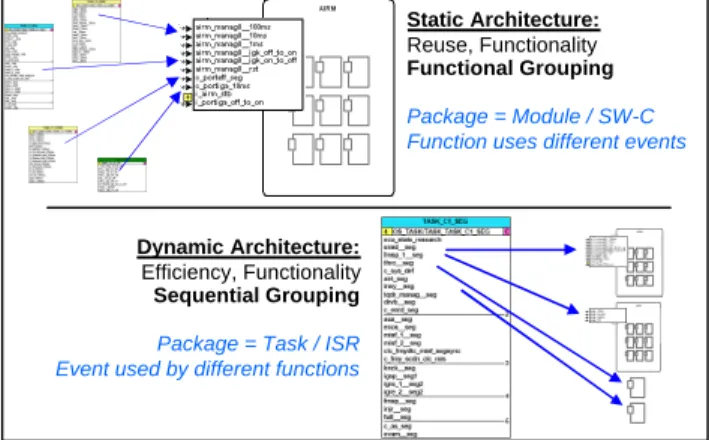
In summary, the dynamic view on the architecture is orthogonal to the static view, without simple link: A function uses various events, while an event is used by various functions.
Fig. 17: Static vs. Dynamic architecture of EMS In this context, variables are widely exchanged between SW-Cs, and between operating system tasks. As an example, the engine speed information (in rpm) is used in 1200 lines of code (out of 250.000), 250 SW-Cs (out of 1200), and is accessed around 700 times every 10ms. Therefore the mechanism to access this information must be efficient in term of HW resources consumption (RAM, ROM, CPU load).
Activation Response time Deadline Function in Task Dynamic Architecture: Efficiency, Functionality Sequential Grouping Package = Task / ISR Event used by different functions
Static Architecture: Reuse, Functionality Functional Grouping Package = Module / SW-C Function uses different events
4. Integration faults and how to avoid them
Like described in a previous document [2], dynamic architecture failures can be classified in 3 categories: intrinsic to the reused component, intrinsic to the frame it is plugged into, or finally failure due to an integration error or incompatibility.
In the first category are the typical problems of infinite loops, wrong pointer initializations, recursivity, interrupt disabling. They are independent of the integration environment, and a verification needs to be done only once on a SW-C, independently of its reuse level. A correct SW-C will be correct even if reused many times on different platforms. On the other side, a faulty SW-C will be faulty on any integration platform. These typical problems are detected by peer reviews, architecture mechanisms, unit testing, or static analysis tools generally available on the market.
The second category of problems refers to the behavior of the project the SW-C is plugged into. CPU overload, or stack overflow are generally detected by embedded mechanisms, by static analysis tools, or by a combination of those. Regular measurements are done along the complete project life, in order to react before the limits are exceeded. In this paper, we will focus on the third category of problems, which concerns the behavior of a SW component once it is integrated in the complete project. As the integration environment changes (e.g. due to the influence of other SW components), the behavior may change: The same SW-C shows different behavior on 2 different projects, being or not
integrated in the same way2. These problems are
generally less tracked; their specification, formalization, and verification can be a cumbersome job. Their effect is not immediate, difficult to reproduce, and in extreme cases, can be destructive. These problems are:
Wrong recurrences:
A calculation is not executed with the right recurrence, or has an unexpected jitter. In general, this problem is due to an integration error, or to high CPU load conditions.
By static analysis, consistency between expected recurrence and integration task or container can be checked. By regular measurements on bench, engine, or vehicle, and by simulation, the correct
2
It should be specified, here, what means "integrated in the same way", when the 2 integration frames are different. Indeed, integration instructions are dependant on the integrated object itself, but also on the integration environment, which is not portable. This is particularly true on the dynamic aspects.
recurrence of the tasks can checked, as well as their jitters.
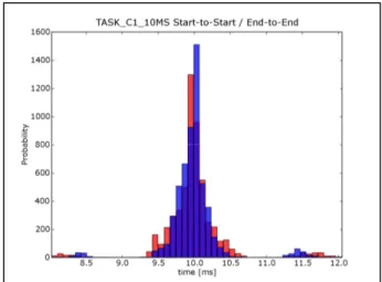
Fig. 18: Jitter verification by simulation
Exceeding deadlines:
Depending on the functionality, a missed deadline can be destructive (e.g. injection update), or have such a light consequence that it is better to simply skip the calculation (e.g. coolant temperature acquisition). An EMS system uses a mixture of hard and soft deadlines, typically in the range of 1ms to 1 sec.
In general, defining the deadline of a functionality is not a simple issue, and requires a good system knowledge. Violating deadlines is a typical problem of integration, as the response time of one function is mostly impacted by the other functions sharing the same CPU: The response time of a function integrated since a while can be impacted by the introduction of a new one.
In order to fulfill the deadlines, priorities are assigned to tasks, based on a standard scheduling policy and task priority scheme. Standard priority orders ensure consistent response times between projects.
Fig. 19: Standardization of priority scheme To verify deadlines, advanced techniques can be used, like schedulability prediction, simulation of the dynamic behavior, or simply measurements. These techniques need a very good understanding of the dynamic behavior and are used by architects.
TASK TDC TASK CAM TASK GAP TASK 5MS TASK 10MS TASK 100MS TASK 1000MS P = 9 P = 3
Fig. 20: Response time verification by simulation
Wrong calculation sequence:
To define the correct sequence between functions of the same event, one of the criteria which can be used is the data flow criterion. A function producing a variable should be located before all the functions that consume this data, in the program flow. Otherwise, the consuming functions will work with an old (or, even worst, non initialized) value. It is also preferable, in general, that all the consumers get a consistent value for the variable, which means that all consumers should be either before, but preferably after the producer module. Furthermore, in some cases, enlacing between functions is required: a function has to be inserted between 2 parts of
another one3.
Fig. 21: Correction of function sequence based on data flow
Thus, defining the right sequence of functions connected to the same event can be a complex job: the below figure shows the amount of direct (produced, then consumed) and reverse (consumed, then produced) data flow in a typical task. Note here that one green or red arrow may encapsulate more than one variable. The amount of arrows (links) here is an additional testimony of the high coupling between EMS functions.
3 At first sight, this seems to be a wrong architecture, but in reality, this may be a consequence of the static partitioning, which is mainly driven by reuse aspects..
Fig. 22: Data flow between synchronous functions To reduce the coupling between functionalities and to better control the sequencing, standard sequence orders or ordering criteria are defined, and sequencing modules are used. Standard initialization mechanisms and standard task scheduling ensure that data are available at the right time.
Fig. 23: Intermediate scheduler reduces integration effort and risk of wrong sequence
Finally, the correct sequence of functions within a task is verified by a static analysis tool, based on data production and consumption order. Due to the big number of links between functions, finding the right precedence order may be a complicated job. Because of algebraic loops, the solution to the precedence problem is not always obvious, and needs some system choices. For the sequence flow across tasks (when defined), the same kind of analysis can be conducted.
Inconsistency of data:
The modification, by a high priority task, of a variable during its use in a low priority task, corrupts the
behavior of the low priority functionality4 , as its 2
parts work with different values for the same variable. This standard problem of real time software is particularly important in EMS context due to the big coupling (and data flow) between functions and between tasks.
4This also applies across different functions which need to work with the same input values. For instance, misfiring, ignition, injection functions are strongly coupled together.
Reverse flow
Direct flow
Call sequence of functions
... ... inj_diag(); ign_diag(); inj_setpoint(); ign_setpoint(); ign_sp inj_err TaskA ... ... inj_err TaskA ign_sp inj_diag(); inj_setpoint(); ign_setpoint(); ign_diag(); 10ms 100ms tdc ... ... ... air_10ms(); inj_10ms(); ign_10ms(); Task 10MS Inj SW-C C 10MS inj SW-C A 10MS inj SW-C B 10MS inj function Deadline = 20ms
Fig. 24: Data inconsistent within 100ms functionality So, to reduce the risk of misuse of shared data, specific design patterns, atomic libraries, restrictions like controlled use of preemption, and encapsulation principles are applied.
The data consistency problem can also be analyzed statically by a tool, by checking the data flow between tasks ("dynamic flow"). Identifying this flow between the tasks is the first step for a better control.
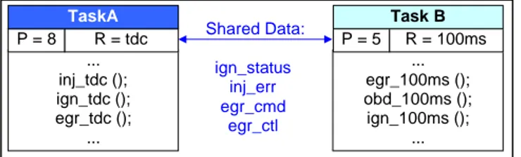
Fig. 25: Shared data between tasks of different priorities and recurrences
Dynamically, it is nearly impossible to verify the consistence of data, as the occurrence of the critical case is very unlikely and difficult to reproduce. This is particularly the case in an EMS context, where regular time based tasks and engine angle based tasks can interact at any time.
5. Organization
In addition to the above measures, an adequate organization allows to control the dynamic architecture:
SW architects analyze new concepts, define
standard methods and mechanisms, and support the projects in their deployment. SW integrators focus on their own project and ensure a correct integration of the reused functionalities. Both are well trained to the architecture mechanisms and constraints, and are highly skilled engineers. Developers of functions are specialists on their own functional scope and know perfectly how to develop a generic solution, portable on different system and HW configurations. They control the internal architecture of their function, in order to ease its maintainability and configurability.
Architecture and integration activities are budgeted, empowered, and considered in the early project planning, as major activities, particularly in a context of intensive reuse.
Architecture assessments are conducted by architecture specialists independent from the projects. They are done at an early phase of the project, to be able to take corrective or preventive actions.
6. Standardization
As seen in the above chapters, the frame a SW-C is plugged into has a major impact on its behavior, in particular in the EMS context of hard real time and high coupling between functions. For instance, a SW-C designed for a non-preemptive environment cannot simply be used in a preemptive one. Even in a given proprietary architecture, the behavior of a reused proprietary SW-C is not automatically the same, due to the different system and HW configurations.
With the trend to integrate more and more external SW-Cs, the need for adaptation layers increases, and consequently the need for HW resources. As long as the number of external SW-Cs is limited, such an integration can be managed. But with an increasing number, a standardization is necessary. Ahead from the pure mechanisms (like interfacing mechanisms), a standardization of the architecture itself is necessary to build complete projects out of SW-Cs. Which events, which recurrences, which links between them (precedence, phasing, exclusion, ...) ? Which scheduling concept, which priorities, which deadlines for the functions, and how to ensure them? Which sequencing between components, and how to control it? Which data to be protected against concurrent accesses, and which mechanism to protect them, compatible with the HW resources constraints? These are some of the challenges to be solved by AUTOSAR or any standard willing to authorize porting of SW-Cs across different platforms.
7. Conclusion
Compared to other automotive areas like car body, an Engine Management System has specific constraints which make the integration of functions more difficult. High coupling between functions, hard and complex real time, and limited HW resources are the ones with major impact on the dynamic behavior. Combined with the strong reuse objectives inherent to the automotive business, these
... inj_tdc (); ign_tdc (); egr_tdc (); ... ... egr_100ms (); obd_100ms (); ign_100ms (); ... P = 8 Shared Data: P = 5 ign_status inj_err egr_cmd egr_ctl ... R = 100ms Task B R = tdc TaskA ... func_tdc (set flag = false)
... func_100ms (use flag = true)
func_100ms (use flag = false)
... Task A Activation Task A (priority = 8) Task B (priority = 5) Task B interrupted within func_100ms
constraints increase the challenge of integration activities. Hidden part of the iceberg, the dynamic integration of a SW-C is certainly much more difficult to put under control than its static one. But there are nevertheless various techniques and means to reach this goal. Standardization will help in this direction, but has to be supported by efficient mechanisms and tools, and has to consider all the facets of the problem.
8. References
[1] D. Claraz / K. Eppinger / L. Berentroth: "Reuse
Strategy at Siemens VDO Automotive : The EMS 2 Powertrain Platform Architecture", in Revue des
Ingénieurs de l'Automobile, 2004.
[2] D. Claraz: "Fiabilité des logiciels embarqués, exemple architecture dynamique logicielle d'un contrôle moteur", SIA congress "La fiabilité des systèmes électroniques et mécatroniques", 2008
9. Glossary
Ecu: Electronic Control Unit
EMS: Engine Management Software Tdc: Top dead centre
SW-C: Software Component (atomic or not) Rpm: Round per minute
Ms: Millisecond