Publisher’s version / Version de l'éditeur:
Vous avez des questions? Nous pouvons vous aider. Pour communiquer directement avec un auteur, consultez la première page de la revue dans laquelle son article a été publié afin de trouver ses coordonnées. Si vous n’arrivez pas à les repérer, communiquez avec nous à PublicationsArchive-ArchivesPublications@nrc-cnrc.gc.ca.
Questions? Contact the NRC Publications Archive team at
PublicationsArchive-ArchivesPublications@nrc-cnrc.gc.ca. If you wish to email the authors directly, please see the first page of the publication for their contact information.
https://publications-cnrc.canada.ca/fra/droits
L’accès à ce site Web et l’utilisation de son contenu sont assujettis aux conditions présentées dans le site LISEZ CES CONDITIONS ATTENTIVEMENT AVANT D’UTILISER CE SITE WEB.
Earthquake Engineering and Structural Dynamics, 14, 3, pp. 369-377, 1986-05
READ THESE TERMS AND CONDITIONS CAREFULLY BEFORE USING THIS WEBSITE. https://nrc-publications.canada.ca/eng/copyright
NRC Publications Archive Record / Notice des Archives des publications du CNRC : https://nrc-publications.canada.ca/eng/view/object/?id=8faab60e-3ac4-4723-ac20-8387ca591886 https://publications-cnrc.canada.ca/fra/voir/objet/?id=8faab60e-3ac4-4723-ac20-8387ca591886
NRC Publications Archive
Archives des publications du CNRC
This publication could be one of several versions: author’s original, accepted manuscript or the publisher’s version. / La version de cette publication peut être l’une des suivantes : la version prépublication de l’auteur, la version acceptée du manuscrit ou la version de l’éditeur.
Access and use of this website and the material on it are subject to the Terms and Conditions set forth at
Rotation effects on measurements of lateral motion
- S t r
m
N21d
i
National Research Conseil nationalno=
1393
1 Coundl Canadade
recherches Canada c . 2'
BI9C3
Institute for lnstitut de.- - - -
Research in recherche en
Construction construction
Rotation Effects on Measurements
of Lateral Motion
by5J.H. Rainer
R~printed from
A N A L Y Z E D
Earthquake Engineering
8
Structural Dynamics Vol. 14, No. 3, May-June 1986p. 369-377
(IRC Paper No. 1393)
Price $2.00 NRCC 26173
Les t r a n s d u c t e u r s i n e r t i e l s q u i m e s u r e n t l e mouvement h o r i z o n t a l s o n t a f f e c t 6 s p a r l a r o t a t i o n de l'emplacement d e mesure. Dans c e document, l ' e f f e t d e l a r o t a t i o n e s t exprim6 p a r une q u a n t i t 6 c o r r e s p o n d a n t B une f r a c t i o n d e l ' a m p l i t u d e du s i g n a l d e t r a n s l a t i o n , e t on montre que c e t t e q u a n t i t e est
inversement p r o p o r t i o n n e l l e au rayon de r o t a c i o n e f f e c t i f de l'eraplacement d e mesure e t a u c a r & d e l a frdquence du s i g n a l . L ' a u t e u r p r e s e n t e d e s procddures d e c o r r e c t i o n pour d i v e r s c a s s u r v e n a n t l o r s d e l a d e t e r t a t n a t i o n d e s a m p l i t u d e s et d e s Pormes modales pour l e s t o u r s , les p o n t s suspendus et les b a t i m e n t s
a
pans d e bois. 11 f w r n t t d e s donndes n u d r t q u e s concernant l at o ~ ~ r du CN et l ' i n t n e ~ ~ b l e de l a Conunerce Court, 3 Toronto ( O n t a r i o ) , e t le pont suspendu Lions' G a t e , 3 Vancouver (Colombie-Britannique). Les e f f e t s de 14 r o t a t i o n s u r les s i g n a u x p r o d u i t s p a r Les t r a n s d u c t e u r s i n e r t i e l s peuvent d t t e i m p o r t a n t s pour l e s t o u r s e t p o n t s suspendus 3
trss
basse frgquence, amis i l s ne semblent g u s r e s e n s i b l e s pour les bdtiments B P-EARTHQUAKE ENGINEERING AND STRUCTURAL DYNAMICS, VOL. 14,36%377 (1986)
ROTATION EFFECTS ON MEASUREMENTS OF LATERAL
MOTION
J. H . RAINER
Division of Building Research, National Research Council Canada, Ottawa, Canada, KIA OR6 SUMMARY
Inertial transducers that measure horizontal movement are affected by rotation of the measurement location. In this paper, the effect of rotation is expressed quantitatively as a fraction of the translational signal amplitude and is shown to depend inversely on the effective radius of rotation of the measurement location and the square of the frequency component of the signal.
Correction procedures are presented for various cases that arise in the determination of modal amplitudes and mode shapes for tower structures, suspension bridges and frame building structures. Specific numerical results are included for the CN Tower and the Commerce Court Building in Toronto, Canada, and the Lions' Gate Suspension Bridge in Vancouver, British Columbia. Rotational effects on signals obtained from horizontal transducers can be significant for very low frequency tower structures and suspension bridges, but are not likely to be of importance for frame buildings.
INTRODUCTION
Movements of structures usually result in a combination of lateral motion and rotations of entire cross- sections or of individual members. The rotations become pronounced for slender cantilevers such as towers or chimneys [Figure l(a)] and for long flexible suspension bridges [Figure l(b)], and are also present in the members of deflecting frame structures [Figure l(c)]. In many cases the rotations can be computed by continuum mechanics or matrix analysis, but when lateral motions of structures are measured these rotations create extraneous signal components in inertial motion transducers. This paper develops a general quantitative analysis of rotation effects on signals from inertial transducers that measure horizontal motion, and presents applicable correction procedures.
Attempts to resolve this problem have been made in the past.'-3 Mention is occasionally made in the literature that acorrection for rotation has been carried out, but no details a r e a ~ a i l a b l e . ~ Usually, however, the rotation effects are simply neglected. The results presented here show that this is justified for horizontal measurements on most conventional structures, but the effect of transducer rotation becomes important for slender structures with low natural frequencies, such as tall towers, chimneys and suspension bridges.
THEORY O F TRANSDUCER RESPONSE
General
The vibration amplitudes of structures are commonly measured by transducers consisting of simple spring- mass oscillators in which the relative displacement of the spring element is converted to an electrical signal. For a damping ratio of about 0.6 of critical, above the resonance frequency of the oscillator the relative spring displacement is nearly proportional to the transducer base displacement. Below the resonance frequency the relative displacement is nearly proportional to the base acceleration; this phenomenon is the basis of a device commonly called an 'acceler~meter'.~, It is therefore sufficient to concentrate our attention on the relative displacement of the oscillator spring, since the accelerometer properties follow directly therefrom.
Common types of accelerometers consist of strain-gauged spring elements or a piezoelectric crystal
0098-8847/86/030369-09$05.00
0
1986 by John Wiley & Sons, Ltd.Received 13 June 1985 Revised 27 August 1985
J. H. RAINER H O R I Z O N T A L I 1 ,,TRANSDUCER
l
-[
\ C E N T R E O F R O T A T I O N TRANSDUCER LOCATION ORIGINAL SHAPE TANGENT TO DEFLECTED SHAPE AT TRANSDUCER DEFLECTED LOCATION MODE SHAPE CENTRE OF ROTATION FOR TRANSDUCERFigure 1. Geometric relations between translation and flexural rotation of structures: (a) cantilever subjected to lateral force P(t); (b) translational and rotational displacement of suspension bridge; (c) deflected mode shape for frame
supporting a mass. Also, sensitive seismometers can detect the displacement of the oscillator mass by induction or frequency modulation. The results derived here for the model of the simple mass-spring oscillator also apply to force-balance or servo accelerometers, whose construction is more complex but whose behaviour below the resonance frequency is similar to that of the spring-mass oscillator.
The assumptions inherent in the subsequent treatment pertain to small deflection theory of structures, from which follows the proportionality between the rotational component and the lateral displacement. Only transducers that measure horizontal motion are considered here; small rotations do not affect the signals from vertical transducers since the rotation effect can be shown to be proportional to the cosine of the angle that the transducer makes with the vertical.
Amplijication factors for transducers
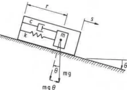
The schematic model of a transducer subjected to translation and rotation is shown in Figure 2. Summation of forces in the horizontal direction, neglecting second-order terms that are connected with small values of 8,
and simplification gives
L ' + 2 / 3 0 0 i + o i r = -s+g8 (1)
where coo = (klm? (natural frequency of transducer, rad/s);
/3
= c/[2 ,/(km)] (damping ratio for transducer); k = spring stiffness;m = mass of transducer;
c = viscous damping coefficient; r = relative displacement of mass;
ROTATION EFFECTS ON MEASUREMENTS OF LATERAL MOTION
Figure 2. Transducer showing forces and coordinate directions
g = acceleration due to gravity;
8 = angle of rotation of transducer base from horizontal.
The angular component (8) is directly related to the translation (s) under the assumptions of small deflection theory:
where R can be interpreted as a radius of rotation (see Figure 1). In general, R can vary with time, but for a steady state oscillation or a particular mode of vibration, this radius of rotation is constant.
The solution of equation (1) is of the form
A
8 = - exp (iat) R
Substitution in equation (1) then gives the ratio of relative displacement of the transducer mass to the displacement of the base
Be-@
-- -
a 2+
g/R A-
a2+
i2pawo+
wi Definition of the frequency ratioa
Q = -
Wo
and computation of amplitudes gives B
-
-
Q2 + g / R o 2A
-
[(I-
R2)2+
(2pR)2]+Equation (6) shows the relationship between the signal amplitude indicated by the transducer and the horizontal amplitude of motion of the transducer base.
Neglecting the second term in the numerator, the angular rotation term, results in the well-known amplitude relationship for the relative displacement of the transducer mass subjected to base displacement:
Equation (4) shows that the inclusion of angular motion produces no additional phase shifts in the transducer as long as 8 is in the same positive coordinate direction as s (shown in Figure 2). When 8 is in the opposite direction, the angular contribution is subtracted from the translational component. This is accounted for, however, by a consistent use of the sign convention.
372 J . H . RAINER
CORRECTION PROCEDURES FOR ROTATIONAL COMPONENT
General
From equation (6) it may be seen that the rotational and the translational components are related by the ratio of g/R& to R2, which for a = 2nL can be expressed as
Equation (8) thus shows what proportion of the true horizontal signal arises from rotation. The total signal (S)
obtained from the transducer is then given by
Equation (8) indicates that the excitation frequency ( f ) is more dominant in determining the influence of rotation than the radius ( R ) . Thus, unless the radius of rotation ( R ) is extremely small, the rotational component will be a signficant fraction of the signals from horizontal transducers only for very-low-frequency structures.
Corrections to measured modal amplitudes
The manner in which a correction for rotation can be carried out depends on whether or not for a particular mode or deflected shape the relationship between the amount of rotation and translation is known.
Case A: radius of rotation is known. Structures for which the rotational components are a known proportion
of the translational amplitude are simple ones, for which a closed-form relationship can be established; e.g. a uniform beam or cantilever. For more complex structures, the rotational component can be calculated when the deflected shape or mode shapes are determined numerically. In either case, an effective radius of rotation
( R ) is available via equation (2). The ratio of signal due to rotation as compared to translation is then obtained from equation (8).
The radius of rotation can also be determined graphically when the mode shapes for the structure are available. The projection onto the null line of the tangent from the transducer location on the mode shape to where this tangent intersects the null line gives the radius of rotation. This conforms to the relationship in equation (2) and the illustration in Figure l(a), when sine is approximated by 8, as is consistent with small deflection theory.
Case B: radius of rotation is not known. For some-structures, the amount of rotation that accompanies the
translation is not known a priori from mechanics or has not been determined by other methods. It is often possible, however, to measure the rotation simultaneously with the translation. This is illustrated in Figure
1 (b), which shows a rigid structural member rotating and translating about a centre of rotation. The radius of
rotation ( R ) to the mid-member is given by
The angle 8 is determined by two transducers measuring vertical displacements A l and A2 separated by a distance L, from which
8 = (A1
+
A z ) / L ( 1 1 )However, substitution of 8 from equation (11) into equation (10) gives the uncorrected radius of rotation, since only the total signal (5) is known and not the true horizontal component (s). One way to determine the correct R is to use a process of successive approximations. As an initial trial, R is determined from the amplitudes of a particular frequency component of the total signal
(q
and angle (8). Subsequent substitutions use this improved value of R, and convergence with a satisfactory accuracy should be achieved in two or three iterations.ROTATION EFFECTS ON MEASUREMENTS OF LATERAL MOTION 373 Alternatively, substitution of equations (10) and (1 1) into equation (8) gives
The radius of rotation (R) is then computed from equation (8).
Case C: radius of rotation is zero. This corresponds to the limiting case where only rotation occurs, but no translation, as for example at a nodal point of a lateral mode of vibration. Equation (2) becomes indeterminate and the subsequent derivation is not applicable. However, setting sin equation (1) to zero, one obtains for an angular motion 8 = 8exp(iat) and relative displacement of transducer mass r = Bexp(i(at
-4)):
I Thus, for a given value of 8 such as from equation (1 I), the signal obtained from the transducer will correspond to a fraction of gravitational acceleration divided by the resonance frequency of the transducer times the amplification factor for the single-degree-of-freedom oscillator. This demonstrates that a spurious acceler- ation signal can be obtained from the transducer that is subjected only to rotation and no horizontal motion, and is particularly pronounced for instruments having low resonance frequencies (coo).
EXAMPLES O F ROTATION EFFECTS CN Tower, Toronto, Canda
The structural details for the C N Tower are presented in Reference 7 and the mode shapes are shown in Figure 3, along with the respective tangents to the transducer locations at the tip and below the lower observation platform. The radii of rotation for the various modes and the ratio C representing the rotational signal as a portion of translation are shown in Table I.
Additional examples of rotational corrections determined from the mode shapes for towers and chimneys are presented in Reference 8.
Suspension bridge with coupled horizontal-torsional modes
The measured horizontal component for a coupled mode of vibration of a suspension bridge will be affected by the simultaneous rotation of the cross-section of the bridge. The amount of coupling in a particular mode is reflected in the radius of rotation of a particular cross-section of the bridge. Knowledge of this radius is essential for sectional model studies in wind tunnels in connection with aerodynamic stability investigations. A correct determination of the radius of rotation as part of the measured modal characteristics is therefore of great practical significance.
The rotational correction for coupled horizontal-rotational motion of a suspension bridge can be dealt with as described under Case B; that is, the radius of rotation is not known, but the rotational component can be measured simultaneously with the horizontal one by monitoring the signals from vertical transducers near the two outside edges of the roadway. The correction term is then computed from equation (12) and the radius of rotation determined. This is illustrated for the measured first antisymmetric torsional mode of the Lions' Gate Suspension Bridge in Vancouver, Canadag. l o shown in Figure 4:
natural frequency of mode, f = 032 Hz;
distance L between vertical transducers = 11.7 m;
measured sum of vertical transducers A, + A , = 1.0 signal unit [Figure l(b)]; uncorrected horizontal displacement S = 1.0 signal unit;
measured rotation 8 = (A,
+
Az)/L = 1-0/11.7 ; uncorrected radius of rotationR
= 318 = 11-7 m;J. H. RAINER
MODE 1 2 3 4 5 6
f., Hz 0.124 0.276 0.488 0.834 1.036 1.841
1
Figure 3. Calculated vibration modes of CN Tower, Toronto (adapted from Reference 7)
Table I. Rotational to translational signal ratio C for CN Tower Radius of rotation, R* (m) Signal ratio C Mode Frequency Transducer 1 Transducer 2
no. (Hz) (tip) (lower platform) Transducer 1 Transducer 2
1 0.124 114 133 0142 0121 2 0276 44 a, 0074 0 3 0.488 24
-
30 0043-
0035 4 0.834 17 a, 0021 0 5 1.034 13 a, 001 8 0 6 1.841 9.6 0 (node) 0.008 a, * See Figure 3.ROTATIONAL COMPONENT A1 + A2 (SEE FIG. l b l
---
UNCORRECTED HORIZONTAL COMPONENT CORRECTED HORIZONTAL COMPONENTROTATION EFFECTS ON MEASUREMENTS OF LATERAL MOTION 375 ratio of components of rotation to translation [equation (12)] gives C = 0.261; i.e. the rotational signal
component is 261 per cent of the true horizontal one; corrected s = (0739) (1.0) = 0.739 units;
s 0739
corrected radius of rotation R = - =
-
= 8.7 m;e
i.o/ii.7Suspension bridges with uncoupled horizontal and torsional modes
The horizontally placed transducers will also respond to rotations that are not of the same frequency as the horizontal modes. Thus, the torsional modes will produce signal components in the horizontal transducers even though the torsional and horizontal modes are uncoupled. These extraneous signal components will then appear in the Fourier spectrum of the horizontal transducers at frequencies corresponding to the torsional modes. This corresponds to Case C described above. For simultaneous horizontal-torsional measurements, the amplitude of these signals can be verified by means of equation (1 3). Failure to recognize this phenomenon could lead to erroneous interpretation of the measurement results.
The signals from horizontal transducers at or near the top of suspension bridge towers will also be subject to rotational effects. This applies to the components for all modes; i.e. vertical, torsional and horizontal, both for coupled and uncoupled ones. Correction procedures similar to those already outlined for towers would be applicable.
Frame structures4ommerce Court, Toronto
The determination of rotational effects on inertial transducers in frame structures is carried out in the same manner as described above. From the numerical evaluation of the mode shapes, the lateral deformation and angle of rotation at any point can be determined (often with considerable effort, however), and the radius (R) calculated from equation (10). The experimental alternative would require the measurement of angular motion at a point decoupled from horizontal motion, but this is not yet fully realizable. Thus, in practice, determining the radius corresponding to the transducer location may be difficult, if not impossible. Nevertheless, an upper bound solution for rotational effects can be obtained in the following manner.
Since a large proportion of the total lateral displacement in the lowest modes of frame structures is due to 'shear-type' deformations (or interstorey drift) rather than overall 'flexural' deformation (or exterior column shortening), the tangent to the lateral mode shape drawn through the exterior column-beam joints for most regular buildings constitutes an upper bound for the angles of the tangents to the column deformations at the joints. This then is also the upper bound for angular deformation of the beams at the joint, and therefore a radius of rotation derived from this mode shape will give an upper bound for the rotational correction term C. This is illustrated for the first lateral mode of the 57-storey Commerce Court building in Toronto, Canada,". l 2 which has a fundamental natural frequency f = 0139 Hz. The mode shape is shown in Figure 5. For the transducer location at the roof level, R was determined graphically to be 314 m, and from equation (8), the ratio of rotational to translational signal C = 0041. This 4.1 per cent correction due to rotation represents an upper bound, and the actual error is likely to be considerably smaller. Thus, a more detailed investigation is not justified for this case, since errors comparable to this upper bound value appear acceptable for most field measurements.
DISCUSSION
The influence of rotation on the signal from transducers measuring horizontal motion of some structures is of a magnitude that demands some correction to measured data. Of six specific towers and chimneys investigated in Reference 8, the results for the CN Tower presented here yielded the largest correction term of 14 per cent for the tip transducer. This was the largest value for the structures investigated, probably because of the low fundamental frequency of vibration of the CN Tower.
The graphical determination of the radius of rotation (R) is subject to inaccuracies since judgement is required in drawing the mode shape and the tangent at the appropriate location. Since the correction term (C)
J. H. RAINER
0 M E A S U R E D M O D A L A M P L I T U D E S
Figure 5. E-W mode shape for Commerce Court, Toronto
is not highly sensitive to R, but is more dependent on the natural structural frequency (f ), which is precisely
measurable, a reasonable assessment of the influence of rotation can still be obtained by this method. For towers or chimneys for which only modal measurement from horizontal transducers is available, the determination of the radius of rotation would have to be carried out by successive approximations since simultaneous measurement of angular motion on slender structures is not yet practical.
SUMMARY AND CONCLUSIONS
A method has been presented for determining effects of rotation of the transducer mounting on the signal obtained from inertial transducers that measure horizontal motion of structures. The errors can be determined graphically when existing mode shapes can be utilized, but successive approximations to the measured mode shapes are required when no prior knowledge of structural properties is available.
For structures where angular measurements can be made simultaneously with the horizontal one, the correction to the horizontal signal and subsequent calculation of the radius of rotation can be achieved directly. This applies particularly to coupled horizontal-torsional modes of vibration of some suspension bridges.
Numerical examples showed the rotational correction relative to the horizontal component for the fundamental mode of the C N Tower in Toronto to be 14 per cent for the transducer at the tip. The first antisymmetric coupled torsional-horizontal mode for the Lions' Gate Suspension Bridge in Vancouver, Canada gave a rotational correction of 26 per cent relative to the horizontal component. Such deviations from the 'correct' horizontal values appear to warrant correction of signals from horizontal transducers for these
and similar types of structures. An upper bound solution yielded 4.1 per cent for the rotational correction
associated with the fundamental mode of the Commerce Court building in Toronto.
ACKNOWLEDGEMENTS
Portions of the results described were obtained while the author was on study leave at the Institute for Structures and Building Materials, University of Karlsruhe, Federal Republic of Germany. This paper is a contribution from the Division of Building Research, National Research Council of Canada.
ROTATION EFFECTS O N MEASUREMENTS O F LATERAL MOTION 377 REFERENCES
1. W. A. Dalgliesh and H. S. Ward, Discussion of 'Wind deflections of tall concrete frame buildings', J. struct. div. ASCE 97,137@1374 (1971).
2. J. F. Wiss and 0. E. Curth, 'Wind deflections of tall concrete frame buildings', J. struct. div. ASCE 96, 1461-1480 (1970).
3. W. Mohlenbrink, 'Bauwerke unter aerodynamischer Belastung' (Structures subjected to aerodynamic loads), Heft 26, Mitteilungen aus dem Institut fiir Massivbau der Technischen Hochschule, Darmstadt, Germany, Wilhelm Ernst & Sohn, Berlin, 1977. 4. W. H. Melbourne, J. C. K. Cheung and C. R. Goodard, 'Response to wind action of 265 m Mount Isa stack', J. srruct. eng. ASCE 109,
2561-2577 (1983).
5. R. W. Clough and J. Penzien, Dynamics of Structures, McGraw-Hill, New York, 1975.
6. C. M. Harris and C. E. Crede, Eds., Shock and Vibration Handbook, McGraw-Hill, New York, 1961, Vol. 1, Chapter 12. 7. F. Knoll, 'Structural design concepts for the Canadian National Tower, Toronto, Canada', Can. j. civil eng. 2, 123-137 (1975).
8. J. H. Rainer, 'Effect of rotation on motion measurements of towers and chimneys', Building Research Note No. 230, Division of Building Research, National Research Council Canada, Ottawa, 1985.
9. J. H. Rainer and A. M. VanSelst, 'Dynamic properties of Lions' Gate suspension bridge', Proc. ASCE-EM specialty con$ dyn. response
struct. Los Angeles, CA, 243-252 (1976).
10. P. Buckland, R. Hooley, B. D. Morgenstern, J. H. Rainer and A. M. VanSelst, 'Suspension bridge vibrations: computed and measured', I J . struct. div. ASCE 105, 859-874 (1979).
'
11. W. A. Dalgliesh and J. H. Rainer, 'Measurement of wind induced displacements and accelerations of a 57-storey building in Toronto, Canada', Proc. 3rd colloq. indust. aerodyn. Aachen, Germany, 67-78 (1978).
12. J. T. Templin and K. R. Cooper, 'Design and performance of a multi-degree-of-freedom aeroelastic building model', J. wind eng. ind.
T h i s paper