HAL Id: hal-02516710
https://hal.archives-ouvertes.fr/hal-02516710
Submitted on 24 Mar 2020
HAL is a multi-disciplinary open access
archive for the deposit and dissemination of
sci-entific research documents, whether they are
pub-lished or not. The documents may come from
teaching and research institutions in France or
abroad, or from public or private research centers.
L’archive ouverte pluridisciplinaire HAL, est
destinée au dépôt et à la diffusion de documents
scientifiques de niveau recherche, publiés ou non,
émanant des établissements d’enseignement et de
recherche français ou étrangers, des laboratoires
publics ou privés.
Modeling of a Dielectric Barrier Discharge Lamp for UV
Production
Sounil Bhosle, R. Diez, Hubert Piquet, Doanh Le Thanh, B Rahmani, David
Buso
To cite this version:
Sounil Bhosle, R. Diez, Hubert Piquet, Doanh Le Thanh, B Rahmani, et al.. Modeling of a Dielectric
Barrier Discharge Lamp for UV Production. COMSOL Multiphysics User’s Conference, Oct 2008,
Hannover, Germany. �hal-02516710�
Modeling of a Dielectric Barrier Discharge Lamp for UV Production
S. Bhosle*
1, R. Diez
1, H. Piquet
1, D. Le Thanh
1, B. Rahmani
1, D. Buso
11
Université de Toulouse - LAPLACE UMR5213 - 31062 Toulouse Cedex 9 - France
*Corresponding author: Sounil Bhosle - Université Paul Sabatier - LAPLACE 3R2 - 118 route de Narbonne 31062 Toulouse Cedex 9 - sounil.bhosle@laplace.univ-tlse.fr
Abstract: Excilamps are artificial Ultraviolet
sources based on the emission of excimers or exciplexes. These latter are excited states of weakly bound rare gas or halide/rare gas atoms which emit a photon in the UV region when they dissociate. Dielectric Barrier Discharge (DBD) excilamps are promizing UV sources for the future, provided the coupling between their power supply is optimized. The model presented here describes the space and time evolution of a 1D DBD supplied with various waveforms.
Keywords: Dielectric Barrier Discharge,
Ultraviolet, Excimer, Power Supply
1. Introduction
Artificial Ultraviolet (UV) sources are widely used in industrial applications as well as in lighting and medical technology. Usual UV sources are based on electrical discharges in a gas mixture containing mercury. Depending on the gas pressure, the efficiency of such sources can be high, around 60% of conversion of electrical power to UV flux, but with a low power density. However, a high power density can be achieved but with a drastic decrease in efficiency as a reverse effect. As mercury is a harmful element for health and environment, many efforts are carried out to get rid of it. As a result, researches are nowadays led in order to produce powerful, efficient and mercury free UV sources. In this field, Dielectric Barrier Discharges (DBD) in rare gas or halide/rare gas mixtures are promising. These discharges are usually made of a silica glass chamber, including the gas or gas mixture at a pressure between 104Pa and 105Pa, with outer electrodes. Depending on authors, efficiencies between 40% and 60% have been reported for pure Xenon DBD lamps. Xenon/Chlorine excilamp are used in skin treatment: such gas mixture has a very interesting specificity as it emits almost exclusively in the UVB range (280nm-315nm). This radiation affects the immune system and has an especially high efficiency for curing
affections due to the overactivity of this system, such as psoriasis and vitiligo.
One of the key issues for the large application of these excilamps is the coupling between these sources and their power supply.
We have developed a Partial Differential Equation model of a plane excilamp (the geometry is presented on figure 2, in pure Xenon, which is implemented in COMSOL. Depending on the boundary conditions applied, the model can be supplied by various voltage or current waveforms, and the densities of the gas discharge species are computed according to space and time. As a result, different power supply modes can be tested on this model and their efficiencies are computed as the ratio of the mean UV output power on the mean input electrical power.
2. Theory
DBD are typically "out of equilibrium" discharges, which means that thermodynamic equilibrium laws do not apply, even locally. Electrons and heavy particles (ions, at fundamental state or excited atoms, molecules) have drastically different temperatures, the order of magnitude is respectively 10000K and 300/400K, and consequently their general behavior can only be described by Boltzmann's equation. This equation can be found in many thermodynamic books but the reference [1] can be mentioned as an example focused on plasmas.
The general expression for Boltzmann's equation is, in the phase space and for a group of particles named s: Coll s s v s ext s s
t
f
f
m
F
f
v
t
f
=
∇
+
∇
+
∂
∂
δ
δ
r
r
r
r
.
.
(1) with: sf
: distribution function of the specie s. It depends on the positionrr
, the speedvr
and the time t.ext
F
r
: outside force applied on particles s.s
m
: mass of a particle s.∇
r
: nabla operator in the positions space.v
∇
r
: nabla operator in the velocity space.Coll s
t
f
δ
δ
: collision term.The distribution function
f
s of a specie s is such thatf
sd
r
r
d
v
r
3 3
corresponds to the number of particles of type s at time t around the position
( )
r r
r,
v
in phase space. The Boltzmann equation governs the evolution of that distribution function when the specie s is submitted to an outside forceF
r
ext and to collisions. These collisions are included through the termColl s
t
f
δ
δ
which corresponds to the variations of the distribution function caused by elastic or inelastic collisions. It takes into account the number of particles of type s per time unit which are created or which disappear in the elementary volume around the position
( )
r r
r,
v
or which are exchanged with the rest of the phase space.This collision term is generally written as an integration of the product of the distribution functions of the particles involved in the collisions and the corresponding collision cross sections. In that way, the Boltzmann equation is called integro-differential.
As a result, the evolution of the discharge plasma can be described by a system of Boltzmann equations (as many equations as considered species) but the integro-differential characteristic of the equations, their strong couplings and nonlinearities, involve that the system is generally not directly solved. Numerical algorithms usually apply on a system which includes integral expressions for each Boltzmann equation, called the moments of the Boltzmann equation.
The three first moments of Boltzmann's equations correspond, respectively, to the mass conservation, momentum conservation, energy conservation. These equations applied to a discharge plasma usually mention a number of terms, corresponding to the numerous exchanges which take place in the discharge. However, some approximations corresponding to the specific type of plasma which develops in a
DBD lead to a simplification of the moments of Boltzmann's equation.
2.1 Drift-Diffusion Model
The gas pressure in which the discharge is established is, in the case of DBDs for UV production, between 103 and 105Pa, which makes that plasma strongly collisional. In those conditions, the directed energy of the particles can be neglected compared to their random motion energy (thermal energy). This collisional behavior causes the temporal variations of the studied variables (densities, fluxes, temperatures...) to be much weaker than the momentum exchange frequency by collision. This leads to strong simplifications of the momentum conservation equation. With additional approximations (scalar pressure, etc...), the flux of particles s can be written:
s s s s s s
=
sign
q
n
E
−
D
∇
n
Γ
r
(
)
µ
r
r
(2) with: sq
: elementary charge of the specie s.s
n
: density of the specie s. It depends on the positionrr
and the time t.s
µ
: mobility of the specie s.s
D
: diffusion coefficient of the specie s.E
r
: electric fieldTwo terms in the expression of the particle flux can be distinguished: one, related to the electric field, corresponds to the drift motion of the particles (provided they have a charge) and the other corresponds to the diffusion motion which is a collisional effect which tends to uniformize the density. Including the expression of that flux in the mass conservation equation leads to the following drift-diffusion equation:
s s s s s s
D
n
n
V
S
t
n
+
∇
−
∇
±
∇
=
∂
∂
)
.(
r
r
r
µ
(3) with:V
: electrostatic potential. sS
: source term for the specie s.Despite the previous simplifications, the system made of the coupling of the equation (3) written for every considered species in the plasma is still not closed. Indeed, some variables are still undefined.
In order to get rid of the indetermination of the electric field, Poisson's equation can be coupled to the system but a further approximation is needed to get the transport coefficients
µ
s andD
s.2.2 The local field approximation
The energy gained by electrons in the electric field during an infinitesimal lapse of time is assumed exactly balanced by their collision energy losses. This is valid for a plasma in which the electrons have a collision frequency high enough to be in equilibrium with the electric field. In that case, their distribution function only depends on the local electric field
E
r
N
(where N is the density of the gas atoms). Consequently, the collision frequencies (and the source terms), the mobilities and the diffusion coefficients depend as well exclusively on the local field.3. Governing equations
Considering the previous approximations, the plasma is governed by the following closed equation system:
=
∇
−
∇
−
∇
+
∂
∂
=
∇
+
∇
−
∇
+
∂
∂
−
=
∇
−
∇
...
...
)
.(
)
.(
)
(
)
.(
i i i i i i e e e e e e e iS
V
n
n
D
t
n
S
V
n
n
D
t
n
n
n
e
V
r
r
r
r
r
r
r
r
µ
µ
ε
(4)This system contains a Poisson's equation coupled to as many equations as considered species. The subscripts e and i refer respectively to the electrons and to the ions.
After all those approximations, the studied plasma is governed by a coupled Partial Differential Equations (PDE) system which can be numerically solved on a spatial domain
Ω
limited by a surface∂
Ω
provided:- the values of the transport coefficients (mobilities, diffusion coefficients) and the source terms are known as a function of the local
electric field. The literature provides some information about this aspect,
- the boundary conditions are clearly defined.
3.1 Boundary conditions for the species s
Plasma/surface interactions are very complex phenomena which involve all the plasma parameters, the nature of the solid, its surface treatment etc... In our modeling frame, such complex aspects are excluded. The aim is rather to get a simplified, coherent and easy to upgrade model of such interactions.
In the case of DBDs, one could imagine in a first step that the solid surrounding the plasma is a perfect dielectric. In these conditions, considering the absence of mobility of charged particles in such a solid, it comes naturally that the boundary conditions for charged particles is a zero normal flux toward the surface. Indeed, as the dielectric is assumed ideal, no charged particle can cross its surface. However, this approach leads to fundamental problems.
With this approach, it is impossible to describe one of the fundamental properties of a plasma which is its sheath. Indeed, this small charged electric area near the walls is directly linked to the development of a surface charge on the dielectric (and generally, any material in contact with the plasma).
Another problem of this approach is that, under the influence of an electric field, the charged particles will drift toward the wall and form there a quasi-surface charge. That will lead to strong density gradients and consequently numerical divergences
A zero normal flux at the plasma/surface interface forbids as well the emission of charged particles at the walls (the secondary emission for example).
As a result it is obvious that, for a numerical modeling, even in first approximation, the dielectric walls cannot be considered as a simple obstacle to the particles motion. Consequently, a surface charge density localized at the interface dielectric/plasma must be defined. This surface charge strongly depends on parameters such as the nature of the dielectric, its surface treatment, the nature of the charges from the plasma etc... In order to keep the DBD model simple enough to perform computation in a reasonable time, some simplifications concerning the plasma/surface interactions must be taken into
consideration. Then simplified boundary conditions must be established for any considered specie.
Considering the electrons, their mobility in the silica glass is neglected and it will be assumed that the electrons do not penetrate in the dielectric. As a result, an electron in the neighborhood of the dielectric will be trapped at the dielectric surface until:
- the presence of a positive charge coming from the plasma leads to a recombination,
- the electron is released. Indeed, the electrostatic potential well near the dielectric surface has not an infinite dept in reality and there is a probability that the electrons escape from that attraction.
Considering the ions, they will be submitted to the same electrostatic attraction on the dielectric than for an electron. However, once at the surface, they will be neutralized according to mechanisms depending on their nature and on the nature of the dielectric. The dielectric commonly used for Excilamps, and consequently considered here, is fused silica.
When an ion gets in contact with such a dielectric surface, it is neutralized. The involved mechanisms are depending on the ionization potential of the ion and two cases are distinguished [2]:
- if this potential is over 10eV, the ion will recombine at the surface by Auger effect or by a resonant process.
- if this potential is lower than 10eV, the ion cannot recombine at the surface and will cross the wall and then move as an ion in the material.
Atoms considered in the frame of that work are exclusively rare gases and their ionization potentials are above 10eV. Consequently, only the first neutralization mechanism will be considered.
Consequently, the ions in the neighborhood of the dielectric wall are attracted and recombine at the surface, leaving a positive charge attached to the dielectric. It is assumed here that the recombination is instantaneous and that the resulting positive charge fixed on the dielectric can only disappear by recombination with an electron from the plasma.
It is assumed in the frame of that work that neutral particles such as metastable or excited atoms instantaneously loose their energy on the dielectric surface and consequently become
atoms at the fundamental state. Their density is then zero at the surface.
Taking into account all the previous considerations concerning interactions between the different kind of species and the dielectric surface, the equations for the boundary conditions for the system (4) consist in coupling volume densities and surface densities of charges.
The equation of the evolution of the surface density of electrons
n
se (trapped electrons at the dielectric surface) is:i se srec se sdes e sadse se K n K n K n n dt dn − − = (5)
in the right part of this equation:
- the first term corresponds to the attraction of the volume electrons due to the polarization charge of the dielectric. The reaction rate is written
K
sadse.- the second term corresponds to the desorption of the surface electrons with a reaction rate
K
sdes.- the last term corresponds to the recombination of the trapped electrons with ions coming from the plasma volume. The reaction rate is written
K
srec.As a result, the boundary condition for the electrons in volume is a flux condition which represents the balance between the volume electrons adsorbed at the surface, the surface electrons released in the volume by desorption and the volume electrons recombining with trapped positive charges:
si e srec se sdes e sadse n eu =K n −K n +K nn Γ rr . (6)
For the ions, the evolution equation of positive charges density
n
si trapped at the dielectric surface by ion neutralization is:si e srec i sadsi si
K
n
K
n
n
dt
dn
=
−
(7) in the right part of this equation:- the first term corresponds to the positive surface charges production by neutralization of the ions coming from the plasma volume. Assuming this neutralization instantaneous, the production rate of positive surface charges is equal to the adsorption rate of volume ions by polarization effect of the dielectric. This adsorption rate is written
K
sadsi.- the last term corresponds to the recombination of the positive surface charges with volume electrons. The reaction rate is written
K
srec.The boundary condition for the ions is a flux condition which represents the losses by neutralization and by recombination with surface: i se srec i sadsi n i
u
=
K
n
+
K
n
n
Γ r
r
.
(8)Neutral species such as metastables are supposed to loose instantaneously their energy at the boundary and so coming back to the fundamental state. The boundary condition for these species is consequently a Dirichlet condition:
0
=
s
n
(9)3.2 Boundary conditions for Poisson's equation
The continuity of the potential involves a constraint on the metallic electrodes on the outside face of the dielectrics (Dirichlet conditions). This kind of boundary condition allows the user to define the applied voltage on the DBD. For example, if the DBD is supplied with a sine wave form at 50kHz and with a maximum amplitude of 5kV, the boundary conditions will be:
) 10 50 2 sin( 5000 ) 2 ( ; 0 ) 1 (electrode V electrode 3t V = = π × (10) On the other hand, a Neumann boundary
condition can be used on one electrode. In this case, the electric field is imposed at the boundary of the neighbor dielectric which is directly associated to the total current flowing in the discharge. For example, if the DBD has a dielectric surface of A and is supplied with a current
I
, the boundary conditions will be:dt A t I electrode V electrode V t
∫
= ∇ = 0 ) ( ) 2 ( ; 0 ) 1 ( εv (11) With the boundary conditions (10) and (11),the discharge can be supplied either in voltage or in current.
4 Methods
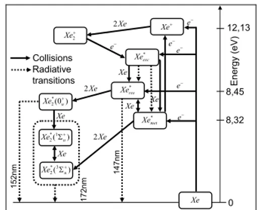
The model previously described is implemented in COMSOL, considering a DBD
in pure Xenon, with 8 different species according to figure 1. * met Xe * res Xe * exc Xe + Xe + 2 Xe ) 0 ( * 2 +u Xe ) (1 * 2 + Σu Xe ) (3 * 2 Σ+u Xe Xe − e − e − e − e E n ergy (e V ) 0 8,45 12,13 8,32 Xe 2 − e Xe Xe Xe − e Xe Xe Xe 2 Xe 2 Collisions Radiative transitions 152nm 17 2n m 14 7n m
Figure 1. Kinetics chosen for the DBD in pure Xenon
Each specie corresponds to a diffusion-convection, transient analysis, equation coupled to Poisson's equation. The ODE governing the surface charges,
n
se andn
si, are implemented through "weak form, boundary" equations.The model is solved in a geometry corresponding to [3], which means a homogeneous discharge between two plane electrodes covered with dielectrics (with a relative permittivity equal to 4, which approximately corresponds to the silica glass). Edge effects are neglected and consequently, the problem can be solved in 1D. The figure 2 presents the discharge geometry and the associated resolution domains. The resolution domain for all the species is between points B and C, which corresponds to the discharge domain. The boundaries are consequently at these two points. For the potential, the resolution domain is from point A to point D. The boundaries are in this case the points A, B, C, D. The metallic electrodes are assumed infinitely thin and they are only supposed to fix the potential at 0 in A (mass connection) and the voltage (or current) source in D.
Inter-electrode space (discharge volume) is filled with Xenon at 5.3x10⁴Pa (400 torrs).
Streamline diffusion was used to stabilize the numerical solutions for electrons and ions.
0.002 0.0060.008 Metal electrodes Dielectric layers (dimensions in m) Discharge gap to the mass to the voltage generator x (m) 0 2.10-3 6.10-3 8.10-3 A B C D
Dielectric Discharge gap Dielectric
Figure 2. Discharge geometry and associated
resolution domains
5 Numerical Model
5.1 Spatial and temporal evolution of the species
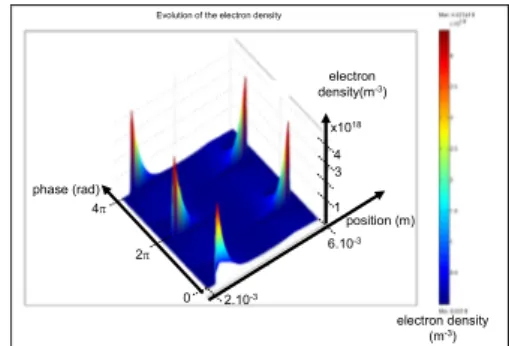
The figures 3 and 4 present the evolutions, in the discharge volume, respectively of the electron density and excimer density on two periods of sine wave 50kHz, 8kV peak, voltage source, when a permanent regime is achieved.
1 2.10-3 3 4 x10¹⁸ electron density(m-3) position (m) 6.10-3 phase (rad) 0 2π 4π electron density (m-3)
Evolution of the electron density
Figure 3. Evolution of the electron density.
2.10-3 4 6 x10¹⁹ 3Σu+ excimer density (m-3) position (m) 6.10-3 phase (rad) 0 2π 4π 2 3Σu+excimer density (m-3) Evolution of the excimer density
Figure 4. Evolution of the excimer density.
5.2 Evolution of the electrical parameters
Figure 5 presents the spatio-temporal evolution of the electric field in the discharge.
-5 2.10-3 5 x10⁶ Electric field (V.m-1) position (m) 6.10-3 phase (rad) 0 2π 4π 4.10-3 Electric field (V.m-1) Evolution of the electric field
Figure 5. Evolution of the electric field.
Figure 6 presents the evolution of the electrical parameters of the discharge.
0 Pi 2.Pi 3.Pi 4.Pi -10000 -8000 -6000 -4000 -2000 0 2000 4000 6000 8000 10000 Phase (rad) Paramètres électriques en régime permanent
νS (V)
νG (V)
νW (V)
iTx50 (A.m-2)
Electrical parameters in permanent regime
Figure 6. Evolution of the electrical parameters -
S
ν
:voltage applied by the voltage source;ν
G: voltage drop in the discharge volume (between points B and C in the figure 2;i
T: total current density (receptor convention).5.3 Evolution of the UV emission
Considering the kinetics of the discharge shown in figure 1, the UV photon flux, at 172nm, at a point x at time t is:
) ( 14 ) ( 13 *3 2 1 * 2
)
,
(
=
Σ++
Σ+Φ
u u Xe XeK
n
n
K
t
x
(12)where
K
13 andK
14 are the radiative dissociation rates of excimers. Consequently, the total flux (UV power emitted) of the discharge at time t is:∫
Φ
=
Ldx
t
x
Sh
t
P
0 172 172(
)
ν
(
,
)
(13) with:h
: Planck's constant (6.626.10-34J.s). 172v
: frequency of a photon at 172nm (1,74.1015Hz).S
section of the discharge (10-4m2)Consequently, the efficiency of the discharge can be computed for various power supply wave forms as the ratio between the mean UV emitted power and the mean electrical power delivered to the discharge.
6. Discussion
The model described here was used to compute the efficiency
η
172 of the excilamp for a sine waveform voltage source of 8kV peak. The results are presented on figure 7 for frequencies between 50kHz and 350kHz.50 100 150 200 250 300 350 0.45 0.5 0.55 0.6 Fréquence (kHz) η172
Figure 7. Efficiency of the excilamp supplied
with a sine waveform voltage source.
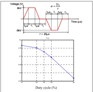
Figure 8 presents the results obtained for a pulsed waveform voltage source at 50kHz, 8kV peak for various duty ratio.
10 30 40 50 80 0.55 0.6 0.65 0.7 0.75 0.8 Rapport cyclique α (%) η172
Figure 8. Efficiency of the excilamp supplied
with a pulsed waveform voltage source.
The results mentioned in figure 7 and 8 show clearly that a pulsed voltage waveform increase significantly the efficiency of the excilamp.
7. Conclusions
The model presented here describes the evolution of a DBD excilamp for various power supplies. It represents an essential tool for the optimization of the coupling between the discharge and its power supply. Moreover, it will help in the design of innovative power supply topologies in order to achieve a high level of UV power and efficiency of excilamps.
8. References
1. J.A. Bittencourt, Fundamentals of plasma physics, Pergamon Press (1986)
2. D.V. McCaughan, R.A. Kushner, V.T. Murphy, Ion Neutralization Processes at Insulator Surfaces and Consequent Impurity Migration Effects in SiO2 Films, Phys. Rev. Let.,
30, 13, (march 1973)
3. A. Oda, Y. Sakai, H. Akashi, H. Sugawara, One-dimensional modelling of low frequency and high-pressure Xe barrier discharges for the design of excimer lamps, J. Phys. D: Appl.
Phys., 32, 2726-2736 (1999) Voltage (V) -8kV 8kV 1µs 1µs 1µs 1µs 20µs 1 τ 1 τ 0 τ 0 τ = τ τ τ α=21 Time (µs) Voltage (V) -8kV 8kV 1µs 1µs 1µs 1µs 20µs 1 τ 1 τ 0 τ 0 τ = τ τ τ α=21 Time (µs) Frequency (kHz) Duty cycle (%)