Publisher’s version / Version de l'éditeur:
Vous avez des questions? Nous pouvons vous aider. Pour communiquer directement avec un auteur, consultez la première page de la revue dans laquelle son article a été publié afin de trouver ses coordonnées. Si vous n’arrivez pas à les repérer, communiquez avec nous à PublicationsArchive-ArchivesPublications@nrc-cnrc.gc.ca.
Questions? Contact the NRC Publications Archive team at
PublicationsArchive-ArchivesPublications@nrc-cnrc.gc.ca. If you wish to email the authors directly, please see the first page of the publication for their contact information.
https://publications-cnrc.canada.ca/fra/droits
L’accès à ce site Web et l’utilisation de son contenu sont assujettis aux conditions présentées dans le site LISEZ CES CONDITIONS ATTENTIVEMENT AVANT D’UTILISER CE SITE WEB.
Paper (National Research Council of Canada. Division of Building Research),
1981-02
READ THESE TERMS AND CONDITIONS CAREFULLY BEFORE USING THIS WEBSITE. https://nrc-publications.canada.ca/eng/copyright
NRC Publications Archive Record / Notice des Archives des publications du CNRC :
https://nrc-publications.canada.ca/eng/view/object/?id=849fd9f5-ba1e-42bf-a425-ebc96c1d9e2b
https://publications-cnrc.canada.ca/fra/voir/objet/?id=849fd9f5-ba1e-42bf-a425-ebc96c1d9e2b
NRC Publications Archive
Archives des publications du CNRC
This publication could be one of several versions: author’s original, accepted manuscript or the publisher’s version. / La version de cette publication peut être l’une des suivantes : la version prépublication de l’auteur, la version acceptée du manuscrit ou la version de l’éditeur.
For the publisher’s version, please access the DOI link below./ Pour consulter la version de l’éditeur, utilisez le lien DOI ci-dessous.
https://doi.org/10.4224/40000458
Access and use of this website and the material on it are subject to the Terms and Conditions set forth at
Field checks on building pressurization for smoke control in high-rise
buildings
Ser
Trn
N21d
n o .
962
c.
2
EtDG
National Research Council of Canada
Conseil national de recherches du Canada
FIELD CHECKS ON BUILDING PRESSURIZATION FOR
SMOKE CONTROL IN HIGH-RISE BUILDINGS
by G. T.
Tamura and C. Y. Shaw
ANALYZED
Reprinted from
ASHRAE Journal
Vol. 23, No. 2, February 1981
p. 21 -25
L I B R A R Y
DBR Paper No. 962
Division of BuiJding Research
Des mesures effectuges sur deux baiments ont rgvdld que des fuites dans les parois de la gaine d'dvacuation des fumges peuvent sdrieusement compromettre I'efficacitd d'un systgme de contr6le des fumdes fonction- nant sur le principe de la pressurisation du baiment. On a aussi observe' qu'une cage d'escalier peut se rem- plir de fumge, surtout en 6td lorsque la porte donnant sur I'dtage en feu et la porte d'issue de la mgme cage sont ouvertes simultandment. En con&quence, les exigences relatives
d
cette mgthode de contrcfle desfumges, publiges pour la premigre fois en 1970, ont gtg rdvisdes dans la nouvelle ddition des "Mesures de sdcuritd en cas d'incendie dans les baiments de grande hauteur" du Code national du baiment du Canada.
Field Checks on Building Pressurization
for Smoke Control in High-Rise Buildings
Measurements made on two buildings reveal that leaky wall construction
L/
of a smoke shaft can seriously affect the performance of a smoke control system. Also revealed is that a stairshaft can be contaminated with smoke, particularly in summer when the stair door on the fire floor and the exit door of the same stairshaft are opened at the same time.
/
pressure on the fire floor than in adja- cent spaces. This is done by raising the pressure inside the building and venting the fire floor. Thus, smoke generated on the fire floor is prevented from spreading to other parts of the building.
Fig. l a shows air flow and pres- sure patterns caused by stack action during winter. Under this condition, with a fire on a lower floor, smoke can invade vertical shafts such as elevator and stairwells and rise to upper floors. If, as shown in Fig. 1 b, the building was pressurized but with the vertical shaft and floor space pressures less than the outside pressures at the lower part of the building, breakage of windows on the fire floor (creating large open- ings in the exterior wall) could cause the pressures of that floor sDace to
G.T. TAMURA C.Y. SHAW
Member ASHRAE porating one or another of these rec- ommended procedures, thus it be- came possible to check the computer predictions against the performance of these real buildings. This paper de- scribes the concept of the building pressurization method and gives the results of field tests on two buildings using this method. It also presents the modifications to the requirements in the National Building Code of Canada that have been made as a result of these tests.2
T
HE 1970 edition of the National Building Code of Canada con- tained various recommendations f o ~ preventing smoke migration through buildings.' These recommendations were originally developed by using a computer model to calculate the pres- sure distribution and air flow between compartments under various operat- ing conditions. Several large buildings were built during the early 70s incor-CONCEPT
The authors are Research Officers. Energy and The basic concept of the building equalize with outside pressures, which Services Section, Division of Building Research.
National Research of Canada, Ottawa, pressurization method for controlling would negate the benefit of the venting
Canada. smoke movement is to create a lower action of a smoke shaft or mechanical
i 1 l C A t AFT
EilUATE ?AESSLlr:ILAl l O h ' A N D RPr-lr:N ':;INDZ:I
E SHAFT FLOOR < o h r e $NS WITH 5 LEVEL otv?. 17c) a A7 IOIV \), TI- - - , - - , . L ,
!N ACEUI'A e l Ut4UEjlUABLE SC'VVLR COr.?DlT! OPE Y
208 AT FIR' F I OOR A N G AT GRACE
tig r rressure ano rrow patterns. ( f a ) sracit acrton ( 1 0 ) madeoi~ate pr~esurrzar~on 3rd broken wind cssuraatton
wtlhou! vttrrttog of frre floor, ( J d J rnrended cunot!lorl, adequafe prpssur~zatlon W I : ~ venfrng of trrs floor. (re) u w 7 e s ~ i a 5 l e summer con- dl~torls wrrh slatr doors o p n a r f ~ r e floor and at grad? / e v e
exhaust.
Fig. l c shows the building so pressurized that the vertical shaft and floor space pressures are equal to, or greater than, the outside pressures at all levels. It should be noted in this figure that with no venting of the fire floor, the air and smoke flow patterns inside the building are the same as in Fig. l a with no pressurization. In this case breakage of windows on the fire floor will cause the pressures to de- crease below those of adjacent spaces. The ideal condition is shown in Fig. 1 d where the building is adequate- ly pressurized and the smoke generat- ed on the fire floor is expelled safely outdoors by a smoke shaft or exhaust fan. Fig. l e shows the undesirable conditions that occur when stair doors are open both at grade level and on the fire floor.
It can be seen that considerable pressurization of the building is neces- sary when a large opening is created in the exterior walls of the fire floor located at a low level. If it can be as- sumed that such an opening is unlikely to be created, as in the case of a win- dowless building or perhaps in a fully sprinklered building, pressurization of the building is not required and me- chanical venting of the fire floor should be sufficient.
The required rate of outside air supply for adequate pressurization-a function of outdoor temperature, building height and air tightness of the building enclosure-is given in Ref. 2. Requirements for venting the fire floor either by smoke shaft, exterior wall vents or mechanical venting are also given in the same reference. Because this method requires the building to be pressurized uniformly from floor to floor, it can only be applied to buildings with non-openable or no windows.
L C I I T L ? A I R
FROM P F R t h t ' I 1 . h '
U N I T S
TEST
The performance of the smoke control systems was checked by taking mea- surements of pressure differences across various separations to deter- mine the air flow pattern in the building and particularly across the designated fire floor enclosure. In some cases, smoke candles were ignited on the fire floor to determine the pattern of smoke flow in the building. Pressure differences were measured with a pressure transducer having a sensitivi- ty of about 0.5 pascal (0.002 in. of water). Flow velocities through damper openings to vent a fire floor were measured either with a deflecting vane type or hot wire anemometer.
Pressure measurements were made throughout the building with the air-handling system operating normal- ly, with it shut down, and with the smoke control system operating. For the sake of brevity, only the results of
the measurements taken on the desig- nated fire floor with the smoke control system operating are reported in this paper.
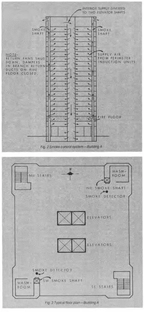
The two test buildings designated as Buildings A and B were constructed between 1970 and 1973. Both use the basic building pressurization method, but they differ in the way the venting of the fire floor is achieved. All outdoor air for pressurization is supplied to the floor spaces through the central air- handling systems except in Building A where part of the outdoor supply air was diverted to the elevator shafts which served as an air distribution duct to the various floors.
RESULTS-BLDG. A Building Profile Occupancy: University;
No. of floors: basement and 22 stories above ground;
Floor dimension: 22.8 by 28.3 by 3.2 m (75 by 93 by 10.5 ft);
Mechanical room: 22nd floor. Smoke Control System Building pressurization:
One interior supply fan-19 m31s (40,200 cf m);
One perimeter supply fan-14.3 m3/s (30,300 cfm).
Venting of fire floor:
Two smoke shafts (three sides of hollow concrete blocks, the fourth side of cast-in-place concrete) with shaft in- ternal area at floor level of 0.42 m2 (4.5 ft2) and between floor level of 0.67 m2 (7.2 ft2);
Smoke damper opening at each floor of 0.20 m2 (2.2 ft2) for each smoke shaft;
Each smoke shaft at top mechani- cal floor connected to horizontal metal duct which terminates at the exterior walls below roof level.
The smoke control system is shown in Fig. 2 and floor plan in Fig. 3. Opera- tion of the system involves the following steps:
a. Automatic actuation of smoke control system with either a smoke de- tector or pull alarm at each floor;
b. Perimeter system to 100% out- door air;
c. Interior system to 100% outdoor air, flow diverted to two elevator shafts by means of dampers in duct work locat- ed at the top mechanical floor;
d. Shutdown of return air fan;
e. Closure of dampers in branch ducts of return system on the fire floor;
1. Smoke dampers at the top and fire floor opened; all smoke dampers ex- cept the one at the top, if required, can be opened independently from the con- trol panel in basement.
TEST RESULTS
Pressures were measured at an out- door temperature of -4°C (25 F) with the smoke control system in operation and the fourth floor designated as the fire floor. The results of the measure- ments indicated that pressures on the fourth floor were lower than those of the floors above and below by 3.7 pas- ASHRAE JOURNAL February 1981
TCH
00
NTROLL T , , r t , , , - , OR ED B Y , STATIN
SMOKE EXHAUST_
SMOKE TO RF DAMPE OPENED . - - - FIRE FL ETURN A . . . . . . . ,IR P L E N IR DAMP--.--
...
DAMPER SMOKE-1
EMENTI
r
JRNf
RETL AIR BAS\RETURN AIR FAN
IE TURNFn " L C UNDER
-2
i i % l ~ ~ ~ ~ AIR FAN
TO
BE
OPERATED O N
FOm
OUTSIDE AIR
UNDESMOKf CONTROL MODE
Fig. 4 Sm one cnnrrol system --Burlding
k
water). Flow velocities through the open smoke dampers on the fourth floor were 0.79 m31s (1670 cfm) and 0.52 m31s (1100 cfm) for the two smoke shafts or a combined exhaust rate of 2.27 air changes per hour, which would be inadequate to prevent possible fouling of the stairshafts in the event of fire.
A separate series of tests was conducted with an outside tempera- ture of (18°C (65 F) to check the leak- age of the smoke shafts. With the floor 23 cals (0.015 in. of water). The pressure
in the pressurized elevator shaft was higher than that of the fourth floor by 13.7 pascals (0.055 in. of water), but the pressures in the stairshafts were lower than those of the fourth floor by 3.5 pascals (0.014 in. of water) for the one stairshaft and 8.9 pascals (0.036 in. of water) for the other. This in- dicated that there was a possibility of smoke entering these shafts. The amount of building pressurization ob- tained was 122 pascals (0.49 in. of
spaces pressurized to 77 pascals (0.31 in. of water) and the smoke dampers open at the top only, flow velocities were measured near the top of the two smoke shafts. From these measure- ments, the rates of air flow were calculated to be 1.04 m3/s (2200 cfm) and 0.80 m31s (1700 cfm) which represented the rates of air leakage flow from the floors into the smoke shafts. Examination of the smoke shaft construction indicated that the gasketed smoke shaft dampers were relatively airtight, but the wall con- struction appeared to be leaky par- ticularly at joints between the top of the concrete block walls between floors and the concrete floor slab as well as between the concrete block walls and the cast-in-place concrete walls. Using the average measured pressure differential across the smoke shaft of 22 pascals (0.088 in. of water) and the total leakage flow of 1.04 m31s (2200 cfm), the total leakage area for the one smoke shaft was calculated to be 0.29 m2 (3.1 ft2) or approximately 0.014 m2 (0.15 ft2) per floor which represented 7% of the opening of a smoke damper.
With smoke dampers open at the fourth floor as well as at the top, flow rates at the top of the two smoke shafts were 0.93 m31s (1960 cfm) for both. Measured flow rates through the open smoke dampers at the fourth floor were 0.26 m31s (550 cfrn) for the one and 0.38 m31s (810 cfrn) for the
other smoke shaft or 28 and 41% of the total flow rate respectively.
With the smoke control system operating, the bottom exit door of one of the stairshafts was opened to the outside. The pressure of the stairshaft, which was indirectly pressurized from the pressurized floor spaces, was reduced causing an adverse pressure differential across the stair door at the fourth floor of 25 pascals (0.100 in. of water). When it was also opened, a flow of air from the fourth floor into the stairshaft was felt at the door opening. This indicated that under this condition smoke could, in the event of fire, flow into the stairshaft.
SUMMARY
The tests indicated that the rate of air exhaust through the smoke shaft was not sufficient to decrease the pres- sures in the vented floor below those of the stairshafts. The rate of air flow through the open smoke damper was about one third of the total rate of flow out of the smoke shaft with the re- mainder entering the shaft through leakage openings in the walls. Exami- nation of the smoke shaft construction indicated that its poor performance was probably caused mainly by leaky wall construction. Tests also indicated that opening the stair door at the fire floor and the exit stair door on the ground floor at the same time could result in the flow of air or smoke into stairshafts.
ring B
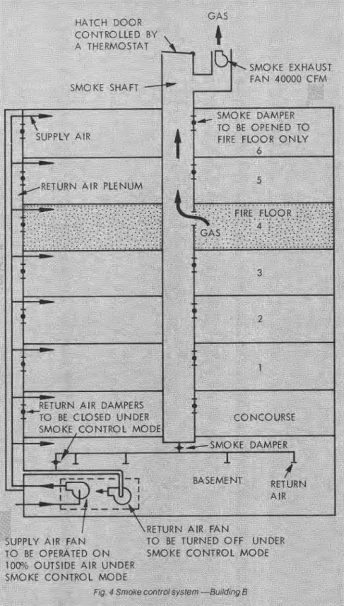
RESULTS-BLDG. B
Building Profile Occupancy: Library;
No. of floors: 7 stories above ground and basement;
Floor area: 3250 m2 (35,000 ft2); Floor height: 3.6 m 12 ft); Mechanical Room:
b
asement. Smoke Control System Building pressurization:One supply air fan in basement. Venting of fire floor:
One T-shaped return air shaft of concrete construction with a total inter- nal cross-sectional area of 4.46 m2 (48
ft2);
Smoke damper o ening at each
f
floor of 1.54 m2 (16.6 ft ) (two multiple blade dampers);An exhaust fan of 18.9 m31s
(40,000 cfm) at the top of the smoke shaft with a motorized hatch door con- trolled by a thermostat also located at the top.
The schematic diagram of the smoke control system is shown in Fig. 4
and floor plan in Fig. 5. Operation of the system involves the following steps:
a. Automatic actuation with either a smoke detector or pull alarm at each floor;
b. Main supply air system to 100%
outdoor air;
c. Shutdown of return air fan with all return air dampers closed;
d. Smoke damper on the fire floor opens and the smoke exhaust fan acti- vates; and
e. When the temperature inside the smoke shaft rises to about 49°C (120 F),
the hatch door at the top of the smoke shaft opens.
Pressures were measured at an outdoor temperature of -8°C (18 F) with the smoke control system in oper- ation and the fourth floor designated' as the fire floor. They indicated that the pressures of the fourth floor were lower than those of the four stairshafts by 1.2 to 6.2 pascals (0.005 to 0.025 in. of water) and of the 2 elevator shafts by 1 and 5 pascals (0.004 and 0.020 in. of water). Thus, the operation of the smoke control system for low tempera- ture fire will likely prevent smoke spread from the fire floor to its sur-
roundings.
The rate of air flow into the smoke
shaft at the fire floor with the exhaust
~
fan operating was 7.3 m31s (15,500cfrn) (2.2 air changes per hour), or 38% of the rated capacity of the fan of 18.8 m3/s (40,000 cfm) (5.7 air changeslhr). This reduction in exhaust rate at the fire floor was caused by the leakage flow from floors other than the fire floor into the smoke shaft through crack openings in the shaft walls, and dampers that had large gaps between damper and damper frame as well as between damper blades. The rate of flow of air into the smoke shaft at the fire floor with the exhaust fan shut down but with the top hatch open was 8.4 m31s (17,800 cfm) (2.5 air changeslhr), slightly higher than the
Fig. 6 Eft ect of leak? of smoke 3
rate with the exhaust fan operating and the hatch shut. The amount of building pressurization was 75 pascals (0.30 in. of water).
Pressure difference readings across the fourth floor stair door in- dicated that opening the exit door at ground level caused a reduction in the stair pressures as in Building A and a consequent reversal in the direction of leakage flow across the stair door; i.e., from the fire floor into the stairwell. When the stair door at the fourth floor was also opened, the measured air flow rate through this door into the stairshaft was 3.35 m3/s (7100 cfm).
Eight 3-minute smoke candles were ignited at the fire floor, two in each corner. Observation of smoke movement indicated that with all doors closed no smoke entered either the stair or elevator shafts at the fourth floor. When both the exit door and the fourth floor stair door of one of the stairwells were opened, however, sig- nificant amounts of smoke entered this stairwell.
SUMMARY
CODE CHANGES To reduce the possiblity of
smoke flow into the stairshafts, they are to be pressurized directly with a supply air rate of 0.14 m31s (300 cfm) per story. Also the supply air rate to pressurize the building must be modulated in accordance with the out- side air temperature to reduce the pressure difference between the vent- ed floor and outside at grade level for summer conditions.
Tests on the smoke control systems of two aforementioned buildings indicate that:
The performance of the smoke shaft in venting the fire floor can be seriously impaired by the extraneous leakage flow into the smoke shaft through the shaft wall construction from floors other than the fire floor; and
There is a likelihood of smoke contamination of the stairshaft when the exit door and the door on the fire floor of the same stairshaft are opened at the same time (Fig. 1 e).
To correct these shortcomings, requirements for the building pressuri- zation method were altered as follows:
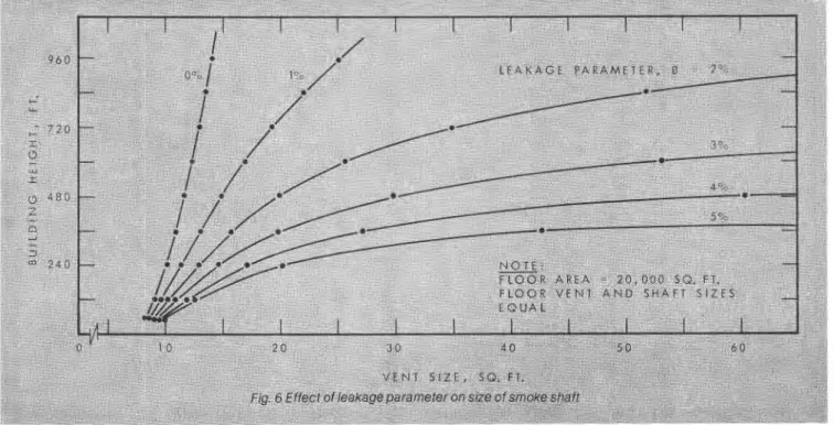
A new table for selecting the smoke shaft size was introduced based on Ref. 3, which takes into ac- count air leakage through the shaft wall. Fig. 6 shows the required vent and shaft area for a given building height and leakage parameter. The lat- ter is expressed as a ratio of leakage area of shaft per story to an open vent area. It shows that the required vent size increases rapidly with an increase in the leakage parameter and also with the building height. This leakage pa- rameter must also be taken into ac- count for the design of mechanical ~ e n t i n g . ~ Good workmanship is essen- tial in achieving a relatively airtight smoke or exhaust shaft for effective venting. Where the return air system is modified to act as a smoke exhaust system it is essential that all dampers except the one at the fire floor close tightly, otherwise the exhaust rate at the fire floor would be less than ex- pected.
ACKNOWLEDGMENT
The authors are indebted to the building owners for granting permission to con- duct tests in their buildings and to the members of their staff for assistance during the tests. The authors also wish to acknowledge the assistance of J.H McGuire in helpful discussions, R.G. Evans for conducting the field tests and M. Galbreath for his contribution to the review of this paper. This paper is a con- tribution from the Division of Building Research, National Research Council of Canada, and is published with the ap- proval of the Director of the Division.
REFERENCES
1. Explanatory Paper on Control of Smoke Movement in High Buildings. Associate Committee on the National Building Code, National Research Coun- cil of Canada, NRC No. 11413, June 1970. 2. Measures for Fire Safety in High Buildings. Associate Committee on the National Building Code, National Reasearch Council of Canada, NRCC No. 15764,1977.
3. Tamura, G.T. and Shaw, C.Y. Basis for the Design of Smoke Shafts. Fire Technology, Vol. 9, No. 3, August 1973, p. 209-222.
4. Tamura, G.T. and Shaw, C.Y. Ex- perimental Studies of Mechanical Ven- ting for Smoke Control in Tall Office Buildings. ASHRAE Transactions, Vol. 84, Part 1,1978. 00
25
Both the pressure measurements and smoke test demonstrated that the smoke control system is effective in preventing smoke spread from the fire floor to its surrounding areas when there is no direct connection to the outside via the exit routes. With direct connection to the outside, as is the case of a stairwell with both the exit door and the stair door of the fire floor open, however, smoke contamination of the stairwell can be expected. As for Building A, the leakage flow into the smoke shaft resulted in a significantly lower exhaust rate at the fire floor than expected.
This publication is being distributed by the Division of Building Research of the National Research Council of Canada. It should not be repro- duced in whole or in part without permission of the original publisher. The Division would be glad to be of assistance in obtaining such per- mission.
Publications of the Division may be obtained by mailing the appropriate remittance (a Bank, Express, or Post Office Money Order, or a cheque, made payable to the Receiver General of Canada, credit NRC) to the National Research Council of Canada, Ottawa. K I A OR6. Stamps are not acceptable.
A list of all publications of the Division is available and may be obtained from the Publications Section, Division of Building Research, National Research Council of Canada, Ottawa. K I A OR6.