HAL Id: hal-03098347
https://hal.archives-ouvertes.fr/hal-03098347
Submitted on 6 Jan 2021HAL is a multi-disciplinary open access archive for the deposit and dissemination of sci-entific research documents, whether they are pub-lished or not. The documents may come from teaching and research institutions in France or abroad, or from public or private research centers.
L’archive ouverte pluridisciplinaire HAL, est destinée au dépôt et à la diffusion de documents scientifiques de niveau recherche, publiés ou non, émanant des établissements d’enseignement et de recherche français ou étrangers, des laboratoires publics ou privés.
Alejandro Kayum Jimenez Zenteno, Aurore Estève, Hélène Cayron, Elise Bou,
David Bourrier, Sylvain Sanson, Denis Calise, Charline Blatché, Christophe
Vieu, Bernard Malavaud, et al.
To cite this version:
Alejandro Kayum Jimenez Zenteno, Aurore Estève, Hélène Cayron, Elise Bou, David Bourrier, et al.. A novel 3D microdevice for the in vivo capture of cancer-associated cells. Medical Devices and Sensors, Wiley, 2019, 2 (5-6), pp.e10056. �10.1002/mds3.10056�. �hal-03098347�
1
A novel 3D microdevice for the in vivo capture of cancer-associated cells
Alejandro K. Jiménez-Zenteno1, Aurore Esteve1, Hélène Cayron1, Elise Bou1, David
Bourrier1, Sylvain Sanson2, Denis Calise3, Charline Blatché1, Christophe Vieu1, Bernard
Malavaud4 & Aline Cerf1
1 LAAS-CNRS, Université de Toulouse, CNRS, INSA, 7 Avenue du Colonel Roche, 31400
Toulouse, France.
2 Rangueil Hospital, Dept. of Urology, Toulouse, France.
3 Department of Microsurgery, Institut National de la Santé et de la Recherche Médicale
UMS006, 1 Avenue du Professeur Jean Poulhés, 31400 Toulouse, France.
4 Department of Urology, Toulouse Cancer Institute, 1 Avenue Irène Joliot-Curie, 31059
Toulouse, France.
A.K Jiménez-Zenteno and A. Esteve contributed equally to this work. Correspondence and requests for materials should be addressed to A.C. (e-mail : acerf@laas.fr)
Keywords: Liquid biopsy; Circulating Tumor Cells; Direct Laser Writing; Electroforming; In Vivo
Circulating tumour cells (CTCs) correlate by their number to the lethal potential of the tumour and can be characterized in terms of molecular properties. The repeated isolation of living CTCs has now appeared as an unavoidable step towards their use as biomarkers in clinical routine. We introduce a 3D stealthy microdevice adapted to the in vivo capture of CTCs in the venous blood flow, on the basis of their physical characteristics, size and rigidity. Embedded in a fluidic bench mimicking an artificial arm vein, it readily captured human prostate cancer cells spiked into donor blood down to a concentration of 1000 cells mL-1. The isolation of cancer cells in
venous circulation was validated in an animal model in vivo. These results open new avenues to the characterization of CTCs in prognosis, personalization of treatments and follow-up, not only as a research tool, but also for repeated monitoring in clinical practice.
2
Analyses of tissue obtained by surgical excision or biopsy drives cancer characterization, risk stratification and treatment of solid tumours. However, procuring representative - and possibly repetitive - samples is hampered by the heterogeneity of cancer and the limitations of invasive access to the primary tumour or metastases. Direct access to the bloodstream and the information that it carries, for instance in the form of cancer cells or of DNA fragments shed by the tumour sites into the blood, have paved the way to the emerging concept of liquid biopsy in cancer care.
Cancer cells reach blood circulation by means of the epithelial-mesenchymal transition (EMT) process, where cells acquire migratory and invasive properties.1,2 Once in the bloodstream, they
are termed circulating tumour cells (CTCs). They are extremely rare within the multitude of blood cells, typically one for one billion of normal blood cells in patients with metastatic cancer, equivalent to a single cell in 10 mL of blood, thus rendering their detection extremely challenging. Countless in vitro techniques have been developed to capture CTCs and allow their enumeration and analysis.3–5 Over the last decade, CTC-isolation assays gained attention due
to the clinical relevance of CTC numeration, since counts are associated with disease progression and treatment failure.6,7
A common in vitro strategy for CTC isolation takes advantage of the epithelial lineage of most solid cancers and of the cell surface expression of specific epitopes such as the epithelial-cell-adhesion-molecule (EpCAM), which has allowed antigen-antibody recognition and sorting of a subpopulation of CTCs. However, recent studies have highlighted an important heterogeneity in antigen expression profiles and a dynamic down-regulation of epithelial proteins in CTC population during the EMT, including EpCAM expression, which may impact the diagnostic performances of any system based on antigen-antibody recognition and, as a consequence, induce a selection bias.8–12
3
Cancer cells are typically larger and less deformable than red blood cells and leukocytes.13
Taking advantage of these physical traits, an in vitro filtration system was developed to enrich CTCs from blood samples using a polycarbonate filter with randomly track-etched micrometer pores.14 This system has demonstrated its functionality with preclinical validation in liver, lung,
prostate, colorectal and other carcinomas.15–19 Other devices have optimized filtration in terms
of capture efficiency adjusting the size, shape, density, and arrangement of micro-pores.20–28
However, relatively high working pressures and mild fixatives such as buffered paraformaldehyde are necessary for these studies to achieve high-throughput filtration in a short processing time. Both driving pressure and cell fixation compromise the viability of the isolated cells, thus, precluding subsequent functional studies.
Resorting to blood samples to analyse the burden of CTCs is prone to conceptual and technical limitations such as the frequency of sampling.29 Indeed, given the rareness of CTCs, any in
vitro system based on a sample of clinically acceptable volume (e.g. 7.5-20 mL) is susceptible to sampling bias.30 In addition, the information collected is liable to pre-analytic alterations
given the drastic variations in blood flow during phlebotomy, environmental changes between the time of blood sample draw and blood sample processing, and the specific blood sample preparation protocols needed for each assay,31 thus compromising the antigen expression and
the intrinsic mechanical properties of CTCs.
Therefore, development of a new generation of devices, adapted to the clinical and conceptual constraints of the monitoring of CTCs, is required to benefit from the information they carry at the time of diagnosis, risk stratification and appraisal of the risk-benefit ratio of treatments. The direct insertion of the capture system within the bloodstream could potentially address the issue of limited blood volume and contribute to the prevention of pre-analytic alterations. Few systems have been developed relying on an immunologic detection targeting CTC membrane markers, using surface-modified medical interventional devices directly inserted into the vein.32–34 More recently, an in vivo system for the recruitment of early metastatic cells was
4
proposed, consisting of a scaffold to be implanted in the peritoneal fat pads for label-free recruitment of early metastatic cells.35 Generally speaking, technologies suffer from previously
described immunologic limitations related to variabilities in antigen expression and/or an implementation hardly amenable to the longitudinal monitoring of CTCs, and seem ill-fitted to meet the constraints of treatment adaptation.36–38
Here we introduce an innovative intravascular medical device for the physical trapping of cancer-related cells from human blood, under physiological venous flow conditions. Conceptually as elegant as a fishing net, the device was designed to be inserted via a medical catheter into a superficial vein of a patient’s forearm, a standard procedure in clinical routine, exposed to the bloodstream for a short period of time and then retrieved for the recovery of trapped cells.
Results
Engineering of a three-dimensional microdevice complying to in vivo flow conditions
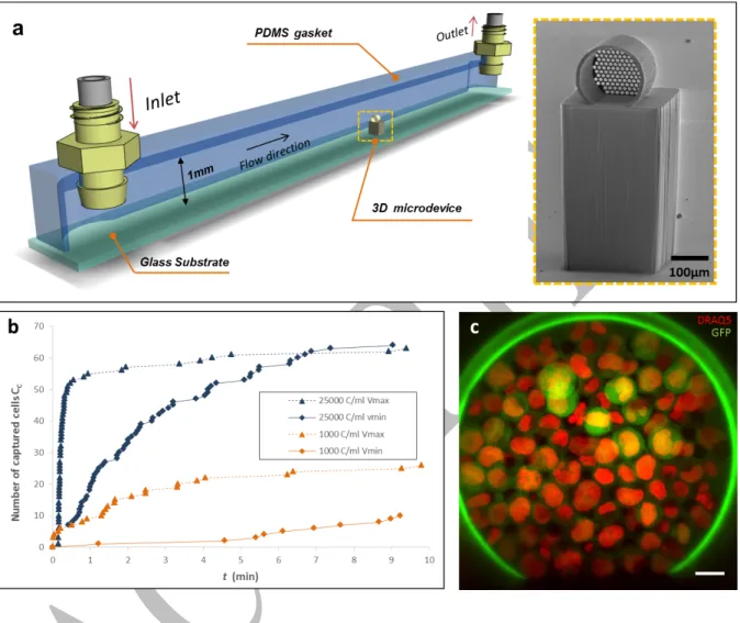
The capture element is a three-dimensional (3D) microdevice engineered as a hollow circular cylinder with a holey membrane at the downstream end-wall (Fig. 1). This configuration, known as dead-end in filtration systems, allows cell filtration when a pressure-driven flow enters perpendicular to the holey-membrane surface, such that larger and less deformable cells entering into the 3D microdevice can be captured. Numerical modeling39 and experimental
data21,40 have suggested that filtration systems could yield an improved selectivity if CTC
isolation is accomplished near the critical pressure, ranging from 200 to 800 Pa. The 3D microdevice was designed to fit into the lumen of conventional catheters used for venipuncture. The design was validated by computational simulations and fabricated based in the specifications detailed in the Suppl. Information section. Two different technological approaches for fabrication were followed: either by a) additive manufacturing based on local polymerization of a photosensitive material using Direct-Laser-Writing (DLW) (Fig. 1a) or by
5
b) multi-layered electrochemical deposition of Nickel (Fig. 1b). The first was versatile enough for rapid prototyping of microdevices that were used to validate, in vitro, under conditions close to the human venous flow, the concept of 3D microfiltration. The second offered robust 3D metal microdevices adapted to the clinical requirements of intravascular access, that were used to validate the prototype in vivo, in an animal model.
Fig. 1 3D microdevice for CTC capture. a Front view of the 3D polymeric microdevice fabricated using DLW (a1). The holey membrane is observed at the end-wall where the total number of pores is np=137, and their diameter is Dp=11.5±0.08 µm. a2 Scanning electron
micrograph magnification of the pores. b Scanning electron micrograph of the metal-based microdevice fabricated by electroforming (b1). The number of pores is np=247, and pores (b2)
6
Fabrication of 3D microdevices using rapid-prototyping for the in vitro evaluation of cell
capture
3D polymeric microdevices were fabricated following a customized process using DLW and a commercially available photoresist (IP-Dip). The microdevice exhibited stable mechanical properties and an acceptable adhesion to the underlying substrate, both physical features rendering it adapted to withstand flow conditions. The diameter of the pores was uniform and reproducible (Dp=11.5±0.08 µm) and each micrometric pore showed nanogroove patterns
(≈200 nm) along the thickness of the holey membrane due to the slicing and hatching parameters set during the fabrication of the microdevice (Fig. 1a2).
The capture capabilities of the 3D polymeric microdevice in flow were analyzed in a custom-made fluidic platform designed to reproduce in vitro the flow conditions found in the basilic vein of the human forearm, the most common venipuncture site, with a reported mean velocity ranging from vmin = 0.072±0.007 m s-1 to vmax = 0.24±0.027 m s-1,41 and a mean pressure of
10mmHg (1333.22 Pa) 42,43. The fluidic platform is a 1 mm-tall channel of square section, in
which the microdevice is positioned at the center as presented in Fig. 2a. A negative-tone photoresist (SU-8) pillar is used as a lift-base both to place the microdevice at the center of the channel cross-section where the maximum of the velocity profile is reached, and thus, avoid the inherent near-zero velocity at the wall surfaces of the channel. This fluidic bench was used to evaluate the 3D microfiltration concept under controlled conditions, and as a platform for real-time observation of capture events.
To assess the cell capture capabilities of the 3D microdevice we first flowed controlled suspensions of a human prostate cancer cell line (PC3), genetically-modified to express green fluorescent protein (GFP) counter-stained with DRAQ5 (λexc = 646 nm, λem= 681 nm), in cell culture medium. PC3 cells ranged from 12 to 21µm in diameter. During cell capture, 3D polymeric microdevices were monitored through the SU-8 micropillar using live inverted fluorescence microscopy and image sequences were recorded. The pumping system (FH100®,
7
Thermo Scientific) was set to reach a fluid velocity in the channel center of either vmin or vmax
by adjusting the rotation speed of the pump at 10 rpm and 40 rpm respectively.
The progressive obstruction of pores as cells were captured was expected from the principle of dead-end filtration, which resulted in a decline of the effective flow passing through the microdevice over time, defined as Effective Flow Rate (Qeff), and ultimate clogging of the holey membrane. This limiting mechanism was evaluated in order to determine a reasonable time span which would allow the capture of CTCs without reaching the clogging stage. Figure 2.bshows the number of captured cells CC as a function of time t. When a highly concentrated
suspension of PC3 cells was flowed (25,000 cells mL-1), at both v
min=0.072 m s-1 and vmax=0.275
m s-1, a significant decrease in the capture rate (Cc/∆t, number of captured cells per time unit)
was observed at 30-40% of the overall membrane capacity. This trait was observed at t ≈ 8 min and and t ≈ 2 min for velocity = vmin and velocity = vmax respectively (Fig.2b). For both, vmin and
vmax, the saturation plateau was reached at similar captured-cell range (Cc=60-80), but the
required time to reach saturation was found to depend on fluid velocity. Visual inspection of the holey membrane evidenced that cells were uniformly distributed all over the surface of the holey-membrane (Fig 2c).
When using a cell suspension of 1000 cells mL-1 the capture dynamics followed a similar trend,
plotted in orange in Fig. 2b. However, the saturation plateau was not reached after the 10 min-filtration, evidencing that a longer exposure to the flow could be foreseen. This result suggests that an acceptable time span of 10 minutes could achieve cell capture at a relatively low-concentration range avoiding saturation of the holey membrane and overexposure of the microdevice to the flow. Moreover, we also observed that the fluid velocity within the channel was directly proportional to the number of cells captured, so a higher velocity increased the likelihood of cell capture. However, considering that in practice, venous flow is not a controllable variable, the in vitro assessment of the capture performance must be performed at
8
vmin, being the less favorable condition. Therefore, to meet future medical applications,
hereinafter, the duration of all fluidic experiments was restricted to 10 min and the mean velocity at the center of the channel to vmin=0.072 m s-1.
Fig. 2 Rapid-prototyping of a 3D microdevice integrated into a fluidic platform. aSchematic perspective view of the fluidic platform where the microdevice on top of the pillar is indicated at the middle of the channel. The inset shows a scanning electron micrograph of the 3D polymeric microdevice on top of a SU-8 pillar. b Recorded capture dynamics when suspensions of 25000 cells mL-1 (blue) and 1000 cells mL-1 (orange) in cell culture medium are flowed at
vmin=0.072 m s-1 and vmax=0.275 m s-1. c Confocal fluorescence image of trapped cells at 25000
cells mL-1. DRAQ5-stained (red) PC3-GFP cells are identified from the green auto-fluorescent
9
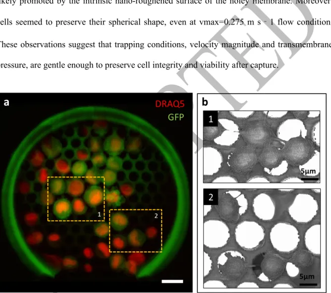
As shown by confocal fluorescence microscopy and electron microscopy (Fig. 3), trapped cells readily sustained direct or reversed increases of the flow rate and remained strongly adherent to the device. We believe that this is related to two factors, one being that cells have the capacity to adhere on our resist material, and second that trapped cells have enough time to assemble dedicated adhesion structures before the end of the capture. Indeed, cell pseudopod protrusions could be observed on electron micrographs confirming proper adhesion to the underlying resist likely promoted by the intrinsic nano-roughened surface of the holey membrane. Moreover, cells seemed to preserve their spherical shape, even at vmax=0.275 m s‐1 flow condition. These observations suggest that trapping conditions, velocity magnitude and transmembrane pressure, are gentle enough to preserve cell integrity and viability after capture.
Fig. 3 Cell morphology of captured cells from a suspension of 5000 cells mL-1 in cell culture
medium. a Composite false-colored image obtained by confocal fluorescence microscopy, where DRAQ5-stained PC3-GFP cells are recognized. The number of captured cells is Cc=39,
and dashed areas correspond to the scanning electron micrograph insets. Scale bar corresponds to 20µm. b Magnifications of micrographs where cell protrusions evidenced cell adhesion to the constitutive material of the holey membrane.
10
To assert cell viability, trapped cells were detached from the microdevice by trypsinization, and collected by reversing the flow within the channel. Collected cells were cultured into different wells of a 96-well plate, and monitored for two weeks. Figure 4 shows representative images of the cultured cells at different time points. We observed the proliferation of cells, starting from <10 cells per well until reaching confluence, with a duplication rate of 44h, similar to PC3 stock culture,45 suggesting that cell integrity is fully preserved during capture (Supplementary
Fig. 1 and Supplementary Information). This observation suggests that captured cells are representative in terms of phenotypic and genotypic characteristics of the initial population of cells, and opens up the possibility of molecular and phenotypic analysis of the trapped cells.
Fig. 4 PC3 cell proliferation after capture and detachment from the holey membrane.
Fluorescence (GFP in green) and optical bright field microscopy images of PC3-GFP cells recovered and cultured after trapping. Days 1, 7, 11, and 14 are shown. Scale bar corresponds to 200μm.
Blood brings a higher degree of complexity than serum due to its heterogeneity and rheological properties, which could influence the performances of the microdevice. This was evaluated in our fluidic bench using whole blood samples from healthy donors.
11
As a control, whole blood from healthy donors collected in ethylenediaminetetraacetic acid (EDTA) tubes was flowed through the fluidic platform, in order to evaluate clogging, fouling of the holey membrane, or non-specific adhesion of normal blood-related components to the microdevice’s material. Blood samples were flowed through the channel for 10 min at
vmin=0.072 m s-1 and rinsed with cell culture medium to remove non-specific cells that might
accumulate within the microdevice. Upon inspection after capture, no evidence of clogging by blood cells was found at the holey membrane level, although minor platelet aggregates and nondescript debris were observed onto the surface or within the membrane pores (Supplementary Fig. 2). Experimental conditions were not adapted to clot formation studies as it is not possible after venipuncture to keep the blood liquid in the absence of calcium chelaters, such as EDTA. Consequently, the microdevice was then used in vitro without any specific surface treatment or coating.
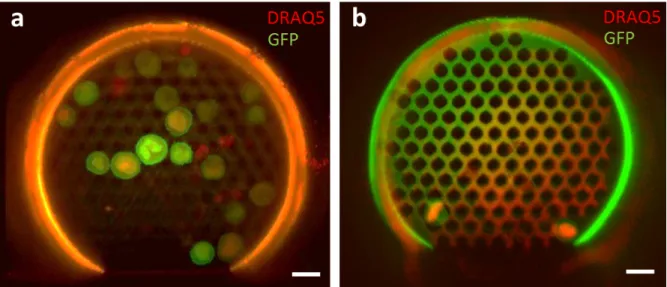
We assessed cancer cell capture under hemodynamic conditions, spiking DRAQ5-stained PC3-GFP cells into whole unprocessed blood from healthy donors at concentrations of 1,000 and 25,000 cells per mL of blood. Similarly to the experiments using cell culture medium, suspensions were flowed through the fluidic test-bench during 10 min at vmin=0.072 m s-1. As
shown in Fig. 5, the microdevice captured PC3 cells from blood samples. It is worth noting that contamination with red blood cells, platelets or leukocytes was negligible throughout the experiments. Note that fewer cancer cells were captured in whole blood as compared with cell culture medium experiments (60-70% reduction) at comparable concentrations. This behaviour could be explained by a possible transient accumulation of red blood cells (RBC), the most abundant cell type in blood (≈5 million per mm3), near the upstream surface of the holey
membrane which could lead to an apparent fouling phenomenon. This effect, known as concentration polarization,46 reduces the effective flow rate through the microdevice due to a
12
Fig. 5 Composite false-colored images of PC3 cancer cells captured by the microdevice from
suspensions of whole human blood. DRAQ5-stained PC3-GFP cells were flowed at different cell concentrations for t=10 min. a Suspension containing 25000 cells mL-1 where a total of
Cc=19 cells were captured and identified. b Suspension of 1000 cells mL-1 with a total amount
of Cc=2 cells captured. Scale bar is 20µm.
The standard operating procedure of intravenous insertion was considered in order to address the practical challenges of using the 3D microfiltration concept in clinical routine. To that end, we designed a double-needle insertion system composed of a puncture needle, an insertion strip-needle guide, and the capture microdevice (Fig. 6a). The concept being to integrate the 3D microdevice along with the insertion strip-needle guide; this assembly, in turn, was placed inside the puncture needle. The overall microdevice-guide ensemble was designed to move freely through the 18G puncture needle, allowing for the microdevice to be retracted. This configuration would enable protecting the microdevice during skin penetration by the puncture needle, and once within the vein, exposing it to the bloodstream. This assembly was evaluated
in vitro using a custom-made fluidic platform with a 3 mm-section channel, comparable in size
and physiological conditions to the basilic vein. For this experiment, the flow conditions were kept at vmin=0.072 m s-1 that is with the peristaltic pump set at 40 mL/min. We confirmed the
13
cell-capture capability of this prototype by fluorescence microscopy. Twenty-one cells (Cc=21) were captured (Fig. 6b), a lower value of CC than compared to the above-described 1-mm
test-bench (Fig. 3). This reduction in capture performance could be attributed to a lower flow velocity to which the microdevice is actually exposed, resulting into a lower effective flow passing through the microdevice. This disruption of the free-stream velocity is likely caused by the double-needle insertion guide, which diverts the flow downstream towards the microdevice reducing the free-stream velocity by half, and consequently Qeff, with a lower transmembrane pressure estimated at 15Pa against 50Pa for the 1mm-channel. However, the microdevice was still exposed to a constant flow and thus cell capture was possible, as demonstrated experimentally.
Fig. 6 Double-needle insertion system for the intravascular access of the 3D microdevice. a The
3D microdevice and the micropillar are integrated onto the strip-needle guide, which allows the insertion and retrieval of the microdevice. This assembly was designed to fit inside an 18G hypodermic needle which is used as puncture needle in clinical routine. The inset shows a SEM micrograph of the microdevice fabricated onto the metallic strip. b Composite of fluorescence images of captured cells using the double-needle insertion system at a cell concentration of 5000 cells mL-1, vmin=0.072 m s-1, and a capture time of 10 min. Lateral-view of the microdevice
where direct cell counting indicates a total amount of Cc=21 cells.
14
Although adhesion of the polymeric microdevice to the strip meets the flow constraints of our experimental in vitro setup, the design was too fragile to withstand the challenges of insertion and recovery needed for its application in clinical routine. To face this limitation, metal-based microdevices were developed and adapted to the geometry of the puncture needle.
Metal-based microdevices for in vivo cell capture
To overcome the above-mentioned limitations of the polymeric-based microdevice, we integrated within the double-needle insertion system the 3D metallic microdevice introduced early in this paper (Fig. 1b). Nickel, a widespread electrodeposited material already reported for the isolation of CTCs and for cell culture of fibroblasts23,47, was selected for the present
study. Successive steps of 2D electrochemical deposition of Nickel were implemented to engineer both the microdevice and the holding strip. Microengineered metallic components were designed to form a 3D device where the holey membrane faces the upstream flow perpendicularly. This represented a major technological breakthrough as 3D metallic devices were fabricated out from a planar technological process. Electroforming being a parallel and low-cost process, this approach could be an alternative to rapid prototyping for large-scale fabrication of the devices. In the case of a single microdevice onto a strip, devices were manufactured as a planar substrate containing a hinge-like joint which allows the microdevice to be folded at 90° before cell capture, then folded back to its original position (Supplementary Fig. 3a). For the case of multiple microdevices onto a strip, complementary-interlocking joints were designed to allow the mechanical assembly of devices. Up to six microdevices could be positioned in series onto the same holding strip (Supplementary Fig. 3b).
The intravascular prototype equipped with 3D metallic microdevices was first tested in vitro, flowing spiked PC3 cells in both cell culture medium and whole human blood, using a 3 mm channel at vmin=0.072 m s-1. Hoechst dye was used as a second identification staining given that
15
as those expressing the double staining, where Hoechst corresponds to the cell nucleus and GFP to the cell membrane, subsequently observed using SEM. To confirm cell morphology and adhesion of trapped cells, suspensions in cell culture medium were flowed at vmin using a single
microdevice onto the strip for 10 min. For cells in suspension at a concentration of 1,000 cells mL-1, the number of captured cells was C
C=11.2 ± 6.38 (mean ± SD, N=5) while for suspensions
at 100 cells mL-1, C
C=6 ± 1.73 (N=3). Cell morphology is in agreement with the observations
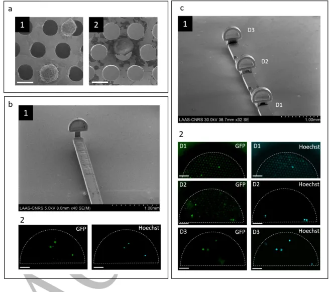
of captured cells in polymer-based microdevices. Cancer cells adhered to the holey membrane keeping a spherical shape and developing pseudopod protrusions (Fig. 7a1). Moreover, cells also remained attached to the holey membrane during subsequent removal from the fluidic channel, cell fixation, and characterization steps after trapping.
Metal-based microdevices were in vitro exposed to a flow of whole blood and a relatively low contamination by normal blood cells was observed within the microdevice, (Supplementary Fig. 4). The level of contamination by blood cells varied among experiments and was blood donor-dependent. When PC3 cells were spiked into whole blood, captured cells exhibited a morphology similar to those from culture (Fig. 7a2). Similarly to polymeric microdevices, the assessment of PC3 capture from whole blood samples using single metal-based microdevices yielded to the capture of CC=2.83 ± 2.45 (N=5) cells when the PC3 concentration was 1000
cells per mL of blood (Fig. 7b). As expected, the number of captured cells Cc proportionally
correlated to PC3 concentration in the initial suspension, detecting down to a concentration of 1,000 cells mL-1 after 10 min.
In order to increase the probability of cell capture, we assessed the possibility to integrate three microdevices in series onto the same holding strip with 2 mm interdistance (Fig.7c1). This distance would allow the stabilization of the blood flow before reaching a subsequent downstream microdevice. When a concentration of 1,000 cancer cells per mL of blood was processed, we identified a total amount of CC=7 PC3 cells distributed among the three
16
series could lead to an increase in the number of total captured cells at a determined cancer cell concentration. This integration both increases the probability of capture at a fixed concentration by increasing the efficient cross-section of the device but also enlarges the domain of linearity of the capture assay to a larger amount of sorted cells.
Fig. 7 Capture of cancer cells in vitro using metal-based microdevices integrated to the
intravascular prototype. a Cell morphology of captured cells, samples from cell culture medium (a1) and from whole blood (a2). b Single microdevice onto the strip (b1) and fluorescence images (b2) on the area of interest after PC3 capture from a suspension of 1000 cells mL-1 in
whole blood. GFP (green) and Hoechst (light blue) expression of captured cells was identified.
c Multiple microdevices were placed in series (c1) and exposed to a suspension of 1000 cells
17
first exposed microdevice to the blood flow, D1, captured a single cell. Second and third device, D2 and D3, captured three cells respectively.
Capture of circulating tumour cells using metal-based devices: in vivo assessment
To determine whether our in vitro findings could be transposable in vivo and thus assess the potential of our approach in clinical routine, we tested an intravascular prototype containing three metal-based microdevices in series in a heparinized animal model (US006 CREFRE, project #CEEA-122 2014-36). We prepared 500 µL of a Hoechst-stained PC3-GFP cell suspension containing approximately 515,000 cells. The solution was infused into the carotid artery of rat model (Fig.8a1), with an injected volume ranging from 410 to 430 µL, due to the dead-volume losses of the needle used during injection.48 As reported in literature.49 after
infusion, into the circulatory system, up to 55-60 percent of the tumour load was expected to home in the liver, lungs and kidney owing to the size of capillaries. Given the total blood volume of our animal model estimated at 20.6 mL, the concentration of PC3 cells circulating in large veins was evaluated from 8,000 to 9,000 cells per mL. The intravascular prototype was introduced into the bloodstream one minute after injection of PC3 cells (Fig.8a2), through direct puncture of the inferior vena cava (estimated diameter from the literature: 3.2±0.1 mm)50 ,
similar in size to the human basilic vein. The exposure to blood flow was limited to three minutes in order to minimize the effect of the innate immune response on circulating PC3 cells and their subsequent clearance from circulation, since the animal model was not immunocompromised. Along this blood-contact time span we did not observe any sign of adverse biological and physiological response from the animal model towards the implanted intravascular prototype. After gentle withdrawal of the prototype, it was inserted into the fluidic platform where it was rinsed to remove the excess of blood, prior to captured cells fixation. We confirmed the presence of PC3 cells into the circulatory system of the rat by drawing 500µL of
18
blood from the femoral vein. The blood sample was directly analyzed on microscope glass slides using conventional fluorescence microscopy (Supplementary Fig. 5).
Using fluorescence microscopy, we quantified a total of Cc=4 PC3 cells captured by our Ni-prototype. These cells were Hoechst and GFP positive and their presence confirmed by SEM. Electron micrographs revealed that captured cells are located within or next to the pores. Representative images of captured PC3 cells are shown in (Fig.8b) and the full SEM view of each microdevice is depicted in Supplementary Fig. 6. As defined in Fig.7, D1 corresponds to the first microdevice exposed to the bloodstream. We found a homogeneous distribution of the total number of captured cells among the three microdevices. Accumulation of blood debris and other residuals along with other blood cellular components (WBCs and platelets) was detected all over the holey membrane surface, however, neither full obstruction of the holey membrane nor RBCs clogging was observed. For the first time, circulating cancer cells were isolated in
vivo using physical capture. These results are a step forward towards the use of the CTC capture
prototype in an intravascular setting to isolate native CTCs directly within the bloodstream, with no pre-analytical steps involved.
19
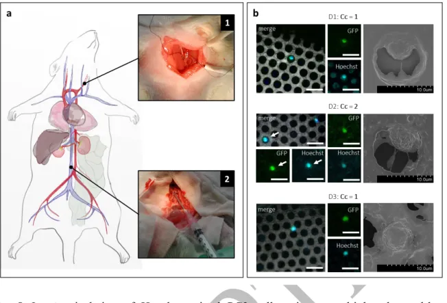
Fig. 8 In vivo isolation of Hoechst-stained PC3 cells using a multiplexed metal-based
intravascular prototype in an animal model. a Schematic diagram of the surgical intervention on a rat model. Cancer cells where infused through the carotid artery (Inset 1), and the intravascular prototype was exposed to the bloodstream within the cava vein during three minutes (Inset 2). b A total of four PC3 cells were identified, distributed among the three microdevices. For each microdevice, from left to right, the overlay of GFP and Hoechst expression of the cell is shown, with the holey membrane as background. In separated channels, GFP and Hoechst are also shown to evidence the double positive expression. At the right, SEM magnifications of the fluorescence-identified cells, depicting a similar morphology than that observed in in vitro experiments. Scale bar corresponds to 20 µm.
Discussion
This study demonstrates for the first time to our knowledge, that the isolation of cancer-related cells based solely on their physical properties is possible under physiologically relevant flow
20
conditions in whole blood, both in vitro and in vivo. This label-free technology is based in an engineered microdevice which isolates larger and less deformable cells directly from blood and can be used for repeated disease monitoring due to its potential integration to medical consumables in clinical routine.
We first demonstrated the possibility to isolate down to 2 cancer cells from suspensions containing 1000 cell mL-1 of spiked PC3 cancer cells into whole blood for 10 minutes. In
conjunction with the results obtained in culture medium (Supplementary Table 1), this suggested that this solution was adapted to the constraints of use in the clinics, and suitable for the isolation of cancer-related cells from the bloodstream of metastatic patients, since most of them correlate with CTC counts ranging from few cells to <2000 cells per mL.51 CTC
enumeration, at concentrations down to 1 cell per mL, has been one of the leading aspects driving the development of in vitro and in vivo isolation technologies. To point our approach towards those levels of sensitivity further improvements need to be carried out.
Indeed, in this study it was evidenced that to achieve, in the future, an improvement in the sensitivity of the 3D microdevice, the effective flow passing through the holey membrane should be increased. From the technological perspective, this corresponds to increasing the holey membrane dimensions as demonstrated in this study, but under in vivo constraints, other patient-related variables will also need to be included such as blood-exposure time and venous flow velocity. Indeed, velocity shows inter and intra-patient variability suggesting that the capture yield of this embarked technology should not be solely assessed in terms of cell capture per minute but also correlated to the actual flow in the vein. Moreover, results from blood experiments did not evidence any clotting or clogging. From this observation we can infer that the microdevices could potentially be exposed to blood flow for longer periods of time. As we can observe from electron imaging, cell attachment to the holey membrane during capture could be related to the local conditions of low velocity, viscosity, and transmembrane pressure within the microdevice. It could also be associated to the physicochemical properties of the substrate
21
such as surface energy and electrostatic interactions that would promote adsorption of proteins from the culture medium.
A second strategy to increase the overall capture efficiency of our system is to multiply the number of microdevices onto the same strip. Recent reports have emphasized the need to increase the sample volume to gain statistical confidence on CTC counts. Embarking this prototype compatible with clinical routine, in vivo, could potentially increase the volume of blood screened and the interrogation frequency providing new information on the kinetics of CTC dissemination, phenotypic and molecular changes occurring in blood circulation as well as the pattern of CTC changes over time. CTC sampling directly from the patient’s vein would avoid issues related with the aging of blood sample and sample preparation, and it may constitute an alternative to recover high quality material with uncompromised viability. Moreover, it could open a new frontier to study cell-cell interactions among tumour cells, platelets and leukocytes when in circulation, since it has been suggested that platelet aggregation and adhesion to CTCs enhance their survival in the bloodstream, as well as interactions with hematopoietic cells such as macrophages and neutrophils. Additionally, the reduced dimensions of the intravascular prototype render it suitable for insertion and blood sampling in diverse superficial veins to investigate the influence of the sampling site on CTC counts.
The comprehensive nature of the in vivo approach was further demonstrated by the Ni-fabricated intravascular prototype on rat models. The robustness of the intravascular device to withstand the experimental procedure including insertion and retrieval of the device, as well as its capacity to isolate cancer cells in blood circulation were demonstrated. The intravascular device did not show evidence of clogging when tested in vitro, as expected when cell filtration is performed at low pressure conditions, along the 10 minutes time span. This due to the EDTA present in blood samples which inhibits platelet aggregation. But its behaviour for prolonged blood-contact times in vivo is still to be investigated. Nevertheless, eventual clogging and
22
adsorption of adhesion-promoter proteins could be prevented using medical grade coatings such as Heparin. It is worthy of note that the average blood flow velocity in the inferior vena cava of a rat is estimated at 5 cm.s-1 and that the animal model was under anesthesia for the
experimentation. Given the surgical procedure the rat was exposed to, it is likely that the blood velocity and pressure were below the reference values used as minima across the in vitro experiments carried out. This suggests the intravascular devices might have been used under unfavorable experimental conditions as compared with experimental conditions validated in
vitro.
We believe that this approach is an alternative for systematic CTC sampling, where captured cells are concentrated in a localized area facilitating CTC identification, with presumably a relatively low contamination by other blood cells. However, the proposed device would have to be improved in terms of design to easily be adapted to conventional CTC characterization and analysis methods, so a systematic CTC identification can be implemented in clinical practice. The proposed approach is not limited to the isolation of prostate cancer cells, PC3, and can be extended to other types of carcinomas as demonstrated by other technologies based on CTC physical isolation. 15–19 Following this reasoning, the design of the microdevice(s) could
also be adjusted in terms of pore size, to address any variability in size and deformability among various types of CTCs present in blood circulation. Thus, we foresee combining microdevices with different pore size. The application of this approach could also be expanded to the isolation of CTC aggregates, and other biomarkers such as other types of circulating cells, as long as the stiffness and deformability conditions are fulfilled. Moreover, the approach here proposed can also be combined with current antibody-based approaches by locally modifying the available surface on the strip. Moreover, the emergence of new techniques and tools for 3D micro- and mesoscale fabrication should enable fabricating more complex architectures using blood-compatible materials, which in fine would improve the efficiency in CTC capture.
23
This proof of concept opens up new pathways for the capture of CTCs, their enumeration and analysis in the framework of cancerous pathology. Being minimally invasive, stealthy and compatible with common medical consumables used in clinical trials, this device could be used for the repeated and systematic monitoring of cancer progression in clinical routine.
Methods
Microdevice Design Rules. Based on the hydraulic resistance theory (see Supplementary
Information), the intrinsic hydraulic resistance of the microdevice is given by RH=8η/π (L/
rc4+t/nrp4), where the design variables are: length and radius of the cylinder (L, rc) and thickness,
pore radius and, pore number (t, rp, np) of the membrane. From the hydraulic resistance model,
we observed that the pore-sized membrane contributes the most to the overall resistance of the microdevice.
The first design constraint to be fulfilled is that the microdevice should be small enough to be inserted into a human vein through a conventional intravenous catheter or hypodermic needle, but large enough to maximize cell capture. The cylinder diameter DC=2rc of the microdevice is
therefore limited by the inside diameter of the 18G needle to be used (i.e., I.D. 860-920 µm) and the dimensions of the assembly corresponding to the 80 µm-thick and 750 µm-wide insertion strip resulting in a microdevice’s effective height of less than 350 µm to the microdevice.
The length of the cylinder LC should allow a non-disturbed upstream region (entrance-length,
Lh=0.05ReDC) so that the velocity profile after the middle length of the cylinder is
fully-developed. Based on pipe flow theory, the entrance-length is roughly equal to the pipe radius and independent from the flow rate at low Reynolds number (Re≤30).54 Therefore, LC must
24
The diameter of the pores Dp=2rp was determined based on the average size of the cancer cell
model used (PC3) and retrofeedback experimentation. The pore diameter was set to Dp=12 µm
for selective filtration with minimal contamination by other blood components.
The number of pores in the filtering membrane n was maximized to cover the maximum area while keeping mechanical stability. Hexagonal geometrical arrangement was chosen to maximize the number of pores keeping a center-to-center distance of 14 µm.
Fabrication of the In Vitro Fluidic Platform. As a first step, a pillar (300x300 µm-lateral)
was patterned at the center of a 350 µm-thick resist-coated (SU-8, MicroChem®) glass substrate (25x25 mm) by a conventional photolithography process (SUSS MA6 Mask Aligner). The substrate was developed in SU-8 developer (MicroChem®), rinsed with isopropyl alcohol, and blow dried with nitrogen. As a second step, the capture microdevice was fabricated on top of the pre-fabricated SU-8 pillar by performing the proper positioning (refer to Fabrication of the 3D Microdevice subsection of Experimental Section). Independently, the fluidic channel gasket made of PDMS (Sylgard® 184 silicon elastomer kit, Dow Corning) was moulded by casting the pre-polymer solution (10:1 base to curing agent weight ratio) onto a mold (1x1 mm or 3x3 mm square section, 12 mm-length), degassing and curing it (1 hour, 100°C). The PDMS channel gasket was then removed from the mold and inlet and outlet were punched. Both, the whole assembly (glass, SU-8 pillar, and microdevice) and the PDMS channel gasket were plasma treated (air plasma, 50W, 0.5 mbar, 5 min), and afterward visually aligned and sealed together, such that the microdevice is center-positioned along the longitudinal axis of the channel. Silicone tubing (Masterflex®, L/S 14) was used to drive the flow into the channel and ensure its pumping using a peristaltic pump (FH100®, Thermo Scientific). For the in vivo prototype testing, a 3x3 mm PDMS gasket (Sylgard® 184 silicon elastomer kit, Dow Corning) was molded by casting the pre-polymer solution (10:1 base to curing agent weight ratio) into a mold (3x3 mm square section, 12 mm-length), prior to degassing and curing (1 hour, 100°C). In this
25
molding step, the customized mold included a lateral port to access a 16G medical catheter (BD Insyte™ Autoguard, 16G x 1.16”) used as a master to mold the inlet access of the in vivo prototype. The PDMS channel gasket was then removed from the mold and both inlet and outlet were punched. Both a standard glass slide and the PDMS channel gasket were plasma treated (air plasma, 50W, 0.5 mBar, 5 min) for subsequent bonding. Silicone tubing (Masterflex®, L/S 16) was used to drive the flow within the channel and pumping was ensured by a peristaltic pump (FH100®, Thermo Scientific) at a rotation speed of 28 rpm (vmin).
Fabrication of the 3D Polymeric Microdevice. The polymeric 3D microdevice was designed
using computer-aided design (CAD) software (Autodesk Inventor® 2015). The fabrication was performed by two-photon lithography using a 3D Direct-Laser-Writing (DLW) system (Photonic Professional GT, Nanoscribe GmbH) equipped with a 63x (Carl Zeiss, NA= 1.4) oil-immersion objective. The negative tone IP-Dip photoresist (Nanoscribe GmbH) was drop casted onto the customized glass-pillar substrate (see Fabrication of the In Vitro Fluidic Platform section of the Experimental Section). The latter was placed into the DLW system under the dip-in laser lithography (DiLL) configuration and subsequently, the microscope stage was manually approached until a z-position (≈10000 µm) allowing visualization of the SU-8 pillar. In order to fabricate the 3D microdevice onto the pre-fabricated SU-8 pillar, the x-y coordinate system of the piezo-stage was first aligned with the laser beam using the camera, and then manually aligned with the pillar by matching the inlet-edge of the 3D microdevice with the upstream-edge of the pillar. The z-position of the piezo-stage was performed by the automatic interface-finder tool, which recognizes the SU-8 pillar top-surface. The optimal laser power was set to 65%, the scan speed to 50 mm s-1, the slicing distance to 200 nm, and the
hatching distance to 200 nm. After polymerization, the microstructure was developed in SU-8 developer (MicroChem®) for 20 minutes, rinsed with isopropyl alcohol during 2 min, and blow dried with nitrogen gas. First, the fabrication of the 3D microdevice and pillar was performed
26
directly onto a customized nickel-titanium alloy (Nickel Titanium-Naval Ordnance Laboratory, Nitinol) strip. A 80µm-thick Nitinol sheet was machined using water jet cutting in order to have strips with total dimensions of 12 mm-length, 800 µm-width as well as a round and sharp ends at each extremity. For each prototype, a single Nitinol strip was taped directly to the center of a 25x25 mm glass substrate in order to facilitate the handling and placement into the DLW equipment. The IP-Dip photoresist (Nanoscribe GmbH) was drop-casted onto the glass/strip substrate. The 3D microdevice and the pillar were integrated into a single CAD file, in order to fabricate both in a single writing process. The microdevice-pillar structure was fabricated at a distance of ≈1.5 mm from the rounded-edge of the strip using the DWL system. The laser power was set to 65%, the scan speed to 50 mm s-1, the slicing distance to 200 nm, the hatching
distance to 200 nm, and a 63x oil-immersion was used. After polymerization, the microstructure was developed in SU-8 developer (MicroChem®) for 20 min, rinsed with isopropyl alcohol during 2 min, and blow dried with nitrogen gas.
Sample Preparation for In Vitro Experiments. PC3-GFP cell line (human prostate cancer
cells modified to express green fluorescent protein) was obtained from the Institute of Pharmacology and Structural Biology of Toulouse. The mean diameter of PC3 cells was measured using an automated cell counter (Scepter™, Merk Millipore) and it was found to range from 12 to 21 μm. Cells were maintained in 75 cm2 flask (T75 flask, Corning®)
containing RPMI-1640 culture medium (Gibco™ GlutaMAX™ medium, Thermo Fisher) supplemented with 10% fetal bovine serum (FBS, Gibco™), 1% Penicilin-Streptomycin (Gibco™, Thermo Fisher) and 1% Geneticin (G418 Geneticin®, Thermo Fisher) at 37°C, in humidified atmosphere containing 5% CO2. Prior to the experiments, cells were labelled with
a nucleic acid marker DRAQ5TM (BioStatus Limited®, 0.5%v, 3min incubation at 37°C) and
rinsed three times with phosphate buffered saline (Gibco™ PBS 1X, Thermo Fisher) before trypsinization (Trypsin-EDTA Gibco™, 3min incubation at 37°C). Stained cells were manually
27
counted with a counting chamber (Fast read 102®, BioSigma) and serial dilutions were performed to obtain the expected cell concentration. Diluted solutions were spiked in controlled concentrations into either blood or culture medium. Human blood samples from healthy donors were provided by the French institution of blood (Etablissement Français du Sang, EFS) in 4 mL EDTA-treated tubes and kept at room temperature for no longer than 1 hour prior to use. Flow experiments with prepared cell suspensions were conducted within the following 3 hours.
Experimental Protocol for PC3-Spiked Samples. Prior to experiments, a pre-rinsing of the
fluidic channel was performed, in reverse flow, with 30 mL of ethanol followed by 30 mL of RPMI-1640 cell culture medium (Gibco™ GlutaMAX™ medium, Thermo Fisher) in the case of 1mm-channels, increased to 50 mL in the case of 3mm-channels. The cell culture medium was kept in the fluidic circuit, in static conditions, and the absence of air bubbles inside the PDMS channel and the 3D microdevice was verified using an optical microscope (inverted microscope Olympus IX71). To pump the solutions (blood or cell culture medium) through the channel, a peristaltic pumping system with an adjustable rotation speed (FH100 Thermo Fisher Scientific Inc) was used either at 10 rpm (vmin) or 40 rpm (vmax) for 1mm-channels and 28 rpm
(vmin) for 3mm-channels. Once the PC3-spiked samples were ready, they were placed at the
inlet of the fluidic circuit and 2 to 3 mL for 1mm-channels, or 5 to 10 mL for 3mm-channels, were pumped to remove the remainder cell culture medium previously introduced. Liquid suspensions containing PC3 cells were flowed during 10 min through the fluidic circuit in a closed-loop configuration where inlet and outlet tubing were placed in the same container. Suspensions were manually agitated before and during the experiments to avoid cell sedimentation. After 10 min, a rinsing step was performed with 30 mL to 50 mL of RPMI-1640 cell culture medium (Gibco™ GlutaMAX™ medium, Thermo Fisher) for 1mm-channels or 3mm-channels accordingly. After rinsing, captured cells were fixed using formaldehyde at 4% (Formalin solution, neutral buffered, 10%, SIGMA-ALDRICH®) with an incubation time of
28
20 min. A final rinsing step with phosphate buffered saline (Gibco™ PBS 1X, Thermo Fisher) was performed and samples were kept in PBS solution.
Live-cell Imaging of Cell Capture Events. Cell capture was monitored during flow
experiments with PC3-cells mixed with cell culture medium. Cell capture events were observed through the SU-8 micropillar using live fluorescence microscopy (inverted microscope Olympus IX71), and images were recorded in DRAQ5 channel (λexc= 646 nm, λem= 681 nm)
with an EMCCD camera (Andor Ixon +). A total of 12000 images were acquired with an interval time between two consecutive images of 88.19 ms, corresponding to the sum of the exposure time (50 ms) and the image read-out time (38.19 ms). Individual cell capture events were identified and accounted using ImageJ software.
Characterization of the Microdevice after Cell Capture. After cell capture and cell fixation,
samples were prepared for fluorescence confocal microscopy characterization. The PDMS-glass ensemble was manually cut with a diamond-tip indenter, following a pre-cutting line in the upstream direction, around 2 mm from the microdevice position. It allows characterization of the microdevice in a vertical configuration where the microdevice is aligned with the microscope objective, allowing direct inspection of the pore-sized membrane. The microdevice was then characterized using both, epifluorescence microscopy (inverted microscope Olympus IX71, 20x air objective) and confocal fluorescence microscopy (upright Leica SP8 confocal microscope, 25x water immersion objective). Signal acquisition in the GFP spectral range (λexc=475 nm, λem=504 nm) was acquired for microdevice imaging, and DRAQ5 (λexc=646 nm,
λem=681 nm) for trapped cell imaging. Direct cell counting was performed from acquired
images. Before SEM characterization, successive dehydration baths were performed using 25%, 50%, 75% and 100% (v/v) of ethanol in PBS 1X. The channel was then emptied and left to dry overnight in air conditions at room temperature. The PDMS gasket of the channel was
29
removed and samples were sputtered (Precision Etching and Coating Systems (PECS), Gatan 682) with a thin-gold layer ranging from 10 to 20 nm. In turn, coated samples were characterized using SEM (Hitachi S-4800). Direct cell counting was performed from acquired images and compared to fluorescence images.
Integration and Mounting of the Prototype for In Vivo Use.
Independently, the insertion-retraction mechanism was prepared through the assembly of a commercially available 20G needle (Terumo, 20Gx 2 3/4”) and an 18G needle (Terumo, 18Gx 1 1/2”), the first needle being the free-moving insertion guide needle and the second needle being the puncture needle. In order to achieve this, first, the plastic needle hub (Luer connector) was removed from the 20G needle, to keep just the needle shaft, and the end-tip of the needle was embedded into the rubber gasket and plunger of a plastic syringe (Terumo, 1 mL syringe). This ensemble of components was placed through the barrel of the syringe, making the 20G needle shaft pass through both elements, the opening of the barrel and the hollow of the 18G needle. In this way, the 20G needle shaft is allowed to move freely into the 18G needle by pulling or pushing the plunger of the plastic syringe. Finally, the Nitinol strip with the fabricated microdevice was glued (Cyanoacrylate instant adhesive, Würth) at the bevel of the 20G needle shaft ensuring a good axial alignment, in order to enable easy displacement through the 18G needle.
Fabrication of Ni-microdevices for the in vivo prototype. The prototype, a composed
assemble of microdevices and holding strip, were designed to fit into a standard 18G medical needle (~650 µm inner diameter). Each prototype is integrated with three microdevices inter-separated by 2 mm. These microdevices, 300 µm-tall and 550 µm-wide, are vertically assembled to a holding strip with a dimension of 290µm x 11mm. Each filtering membrane is composed of 250 pores of 12 µm in diameter. Microdevices and holding strips were fabricated
30
by electrochemical deposition of Nickel following a two-steps lithography process. In a first step, a 10 µm-thick positive resist, AZ4562, was spin coated onto a silicon wafer and UV-exposed in order to define the pore patterns. Then, 5 µm-thick of Nickel was grown using through-mask electrochemical deposition, where the pre-patterned insulating resist limits the regions where material can be deposited. In a second step, similar to the first one, a 200 µm-thick laminated negative resist (WBR-2100) defined both, the millimetric 2.5D support of the microdevices and the holding strips area. 150 µm-thick of Nickel material was once again deposited. We ensured an overlapping of at least 10 µm in between deposited Ni-layers to bond them and increase their adhesion. Finally, silicon wafer was chemically etched (KOH solution) to release the fabricated microdevices and holding strips. Micro-devices were manually assembled to holding strips under binocular using a polymeric holder (name of polymer) fabricated by 3D printing. A drop of EP 630 glue (ratio 100:35, cured at 80°C) was deposited on the backside of the holding strip to fix microdevices on it.
Animal experimentation. All animal experiments were conducted under the guidelines of
animal care, at the Zootechnics platform of the University-affiliated Hospital of Rangueil (CHU de Rangueil), Toulouse. A male rat of 320g in weight and estimated 20mL in blood volume were obtained from Charles River. There were fed and maintained under specific pathogen-free conditions during the week before experiments. Before animal surgical intervention, each in vivo prototype was pre-rinsed in counter-flow, using a customized fluidic platform, with 25 mL of ethanol followed by 25 ml of cell culture media, and devices are maintained in culture media prior to being introduced into the animal's vein. Cell suspensions of Hoechst‐stained PC3‐GFP cancer cells at ~1x10⁶ cells per mL of culture medium in a total volume of 500 μL to reach a targeted final concentration into blood circulation of 25000 cell.mL-1. The rat was subjected to pre surgical preparation (O2 with 4% Isoflurane, 50 µg/Kg Buprenorphine) and kept under anesthesia (O2 with 2% Isoflurane) during the whole intervention. We targeted performing
31
cancer cell capture at the hepatic vena cava, with a mean diameter of 3.2±0.1 mm,9 whereby a surgical procedure was required. A rodent catheter (PE10) was pre-placed in the carotid artery for PC3-sample injection, when required, and the xyphopubic laparotomy was performed to access the targeted hepatic vena cava. The animal was heparinized (40 UI), before exposing the capture microdevices through the inferior vena cava. Once the surgical procedure was performed, the vena cava was punctured with the outer needle of the double‐needle insertion system (Figure 3.14 inset 2) while capture microdevices were at the retracted position, meaning that they were not exposed to the bloodstream at this initial stage. Immediately after, the PC3 cell suspension was injected in the selected region as abovementioned. Approximately a minute after cell infusion, the capture microdevices were exposed to the blood flow using the plunger of the syringe, for a time span of 3 minutes. After this exposure time, microdevices were retracted into the puncture needle and the intravascular device was removed from the vena cava. Immediately after retrieval, the intravascular device was inserted into an empty 3‐mm fluidic channel where microdevices were exposed and rinsed with 50 mL of culture medium in order to remove the excess of blood. With respect to the animals, a volume of 500 μL of blood was extracted from the left femoral vein as control to verify the presence of PC3 cells within the circulation. Finally, animals were euthanized by a lethal injection with pentobarbital sodium. In a subsequent step, microdevices were fixed, dehydrated, and let dry in air conditions for a few hours. Afterwards, strips and microdevices were disassembled for characterization. Finally, a blood sample was extracted from the left femoral vein and the rat was euthanized by lethal injection with pentobarbital sodium. Immediately after retrieval, the intravascular device was inserted into an empty fluidic platform. Microdevices were exposed and rinsed with 50 mL of cell culture media and maintained in the solution. Afterwards, a solution of formaldehyde at 4% (Formalin solution, neutral buffered, 10%, SIGMA-ALDRICH®) was introduced in the channel for 20 min for cell fixation. This step is followed by successive rinsing baths of 25%,
32
50%, 75% and 100% of ethanol diluted in PBS, and then after the channel was let to dry in air conditions at room temperature.
References
1. Thiery, J. P. Epithelial–mesenchymal transitions in tumour progression. Nat. Rev. Cancer
2, 442–454 (2002).
2. Guarino, M. Epithelial–mesenchymal transition and tumour invasion. Int. J. Biochem.
Cell Biol. 39, 2153–2160 (2007).
3. Harouaka, R., Kang, Z., Zheng, S.-Y. & Cao, L. Circulating tumor cells: Advances in isolation and analysis, and challenges for clinical applications. Pharmacol. Ther. 141, 209–221 (2014).
4. Ferreira, M. M., Ramani, V. C. & Jeffrey, S. S. Circulating tumor cell technologies. Mol.
Oncol. 10, 374–394 (2016).
5. Arya, S. K., Lim, B. & Rahman, A. R. A. Enrichment, detection and clinical significance of circulating tumor cells. Lab. Chip 13, 1995–2027 (2013).
6. Hayes, D. F. et al. Circulating Tumor Cells at Each Follow-up Time Point during Therapy of Metastatic Breast Cancer Patients Predict Progression-Free and Overall Survival. Clin.
Cancer Res. 12, 4218–4224 (2006).
7. de Bono, J. S. et al. Circulating tumor cells predict survival benefit from treatment in metastatic castration-resistant prostate cancer. Clin. Cancer Res. Off. J. Am. Assoc.
Cancer Res. 14, 6302–6309 (2008).
8. Armstrong, A. J. et al. Circulating Tumor Cells from Patients with Advanced Prostate and Breast Cancer Display Both Epithelial and Mesenchymal Markers. Mol. Cancer Res. 9, 997–1007 (2011).
33
9. Gorges, T. M. et al. Circulating tumour cells escape from EpCAM-based detection due to epithelial-to-mesenchymal transition. BMC Cancer 12, 178 (2012).
10. Raimondi, C. et al. Epithelial-mesenchymal transition and stemness features in circulating tumor cells from breast cancer patients. Breast Cancer Res. Treat. 130, 449–455 (2011). 11. Krawczyk, N. et al. Expression of stem cell and epithelial-mesenchymal transition
markers in circulating tumor cells of breast cancer patients. BioMed Res. Int. 2014, 415721 (2014).
12. Mego, M. et al. Relationship between circulating tumor cells and epithelial to mesenchymal transition in early breast cancer. BMC Cancer 15, 533 (2015).
13. Seal, S. H. A sieve for the isolation of cancer cells and other large cells from the blood.
Cancer 17, 637–642 (1964).
14. Vona, G. et al. Isolation by Size of Epithelial Tumor Cells. Am. J. Pathol. 156, 57–63 (2000).
15. Vona, G. et al. Impact of cytomorphological detection of circulating tumor cells in patients with liver cancer. Hepatology 39, 792–797 (2004).
16. Hofman, V. et al. Preoperative circulating tumor cell detection using the isolation by size of epithelial tumor cell method for patients with lung cancer is a new prognostic
biomarker. Clin. Cancer Res. Off. J. Am. Assoc. Cancer Res. 17, 827–835 (2011). 17. Matikas, A. et al. Detection of KRAS Exon 2 Mutations in Circulating Tumor Cells
Isolated by the ISET System from Patients with RAS Wild Type Metastatic Colorectal Cancer. Transl. Oncol. 10, 693–698 (2017).
18. Chen, C.-L. et al. Single-cell Analysis of Circulating Tumor Cells Identifies Cumulative Expression Patterns of EMT-related Genes in Metastatic Prostate Cancer. The Prostate
34
19. Hofman, V. J. et al. Cytopathologic Detection of Circulating Tumor Cells Using the Isolation by Size of Epithelial Tumor Cell MethodPromises and Pitfalls. Am. J. Clin.
Pathol. 135, 146–156 (2011).
20. Zheng, S. et al. 3D microfilter device for viable circulating tumor cell (CTC) enrichment from blood. Biomed. Microdevices 13, (2011).
21. Harouaka, R. A. et al. Flexible Micro Spring Array Device for High-Throughput Enrichment of Viable Circulating Tumor Cells. Clin. Chem. 60, 323–333 (2014).
22. Lim, L. S. et al. Microsieve lab-chip device for rapid enumeration and fluorescence in situ hybridization of circulating tumor cells. Lab. Chip 12, 4388–4396 (2012).
23. Hosokawa, M. et al. Size-selective microcavity array for rapid and efficient detection of circulating tumor cells. Anal. Chem. 82, 6629–6635 (2010).
24. Zheng, S. et al. Membrane microfilter device for selective capture, electrolysis and genomic analysis of human circulating tumor cells. J. Chromatogr. A 1162, 154–161 (2007).
25. Lin, H. K. et al. Portable filter-based microdevice for detection and characterization of circulating tumor cells. Clin. Cancer Res. Off. J. Am. Assoc. Cancer Res. 16, 5011–5018 (2010).
26. Desitter, I. et al. A new device for rapid isolation by size and characterization of rare circulating tumor cells. Anticancer Res. 31, 427–441 (2011).
27. Zhou, M.-D. et al. Separable Bilayer Microfiltration Device for Viable Label-free Enrichment of Circulating Tumour Cells. Sci. Rep. 4, srep07392 (2014).
28. Adams, D. L. et al. The systematic study of circulating tumor cell isolation using lithographic microfilters. RSC Adv. 9, 4334–4342 (2014).
29. Leong, S. M. et al. Sampling circulating tumor cells for clinical benefits: how frequent? J.
35
30. Tibbe, A. G. J., Miller, M. C. & Terstappen, L. W. M. M. Statistical considerations for enumeration of circulating tumor cells. Cytometry A 71A, 154–162 (2007).
31. Wong, K. H. K. et al. Whole blood stabilization for the microfluidic isolation and molecular characterization of circulating tumor cells. Nat. Commun. 8, 1733 (2017). 32. Saucedo-Zeni, N. et al. A novel method for the in vivo isolation of circulating tumor cells
from peripheral blood of cancer patients using a functionalized and structured medical wire. Int. J. Oncol. 41, 1241–1250 (2012).
33. Wang, H. et al. Carboxybetaine Methacrylate-Modified Nylon Surface for Circulating Tumor Cell Capture. ACS Appl. Mater. Interfaces 6, 4550–4559 (2014).
34. Zhang, H. et al. In Vivo Capture of Circulating Tumor Cells Based on Transfusion with a Vein Indwelling Needle. ACS Appl. Mater. Interfaces 7, 20477–20484 (2015).
35. Azarin, S. M. et al. In vivo capture and label-free detection of early metastatic cells. Nat.
Commun. 6, ncomms9094 (2015).
36. Blau, C. A. et al. A Distributed Network for Intensive Longitudinal Monitoring in Metastatic Triple-Negative Breast Cancer. J. Natl. Compr. Cancer Netw. JNCCN 14, 8– 17 (2016).
37. Li, Y. et al. Dynamic monitoring of circulating tumour cells to evaluate therapeutic efficacy in advanced gastric cancer. Br. J. Cancer 114, 138–145 (2016).
38. Yin, J. et al. Circulating Tumor Cells Enriched by the Depletion of Leukocytes with Bi-Antibodies in Non-Small Cell Lung Cancer: Potential Clinical Application. PloS One 10, e0137076 (2015).
39. Zhang, Z., Xu, J., Hong, B. & Chen, X. The effects of 3D channel geometry on CTC passing pressure – towards deformability-based cancer cell separation. Lab. Chip 14, 2576–2584 (2014).
36
40. Coumans, F. A. W., Dalum, G. van, Beck, M. & Terstappen, L. W. M. M. Filtration Parameters Influencing Circulating Tumor Cell Enrichment from Whole Blood. PLOS
ONE 8, e61774 (2013).
41. Ooue, A. et al. Changes in blood flow in a conduit artery and superficial vein of the upper arm during passive heating in humans. Eur. J. Appl. Physiol. 101, 97–103 (2007).
42. Baumann, U. A. et al. Estimation of central venous pressure by ultrasound. Resuscitation
64, 193–199 (2005).
43. Munis, J. R., Bhatia, S. & Lozada, L. J. Peripheral venous pressure as a hemodynamic variable in neurosurgical patients. Anesth. Analg. 92, 172–179 (2001).
44. Accardo, A. et al. Multiphoton Direct Laser Writing and 3D Imaging of Polymeric Freestanding Architectures for Cell Colonization. Small 13, n/a-n/a (2017).
45. Picollet-D’hahan, N. et al. The modulation of attachment, growth and morphology of cancerous prostate cells by polyelectrolyte nanofilms. Biomaterials 34, 10099–10108 (2013).
46. Sablani, S., Goosen, M., Al-Belushi, R. & Wilf, M. Concentration polarization in ultrafiltration and reverse osmosis: a critical review. Desalination 141, 269–289 (2001). 47. Sun, T., Smallwood, R. & MacNeil, S. Development of a mini 3D cell culture system
using well defined nickel grids for the investigation of cell scaffold interactions. J. Mater.
Sci. Mater. Med. 20, 1483–1493 (2009).
48. Küme, T. et al. The effects of different syringe volume, needle size and sample volume on blood gas analysis in syringes washed with heparin. Biochem. Medica 22, 189–201
(2012).
49. Gao, J., Dennis, J. E., Muzic, R. F., Lundberg, M. & Caplan, A. I. The dynamic in vivo distribution of bone marrow-derived mesenchymal stem cells after infusion. Cells Tissues