Publisher’s version / Version de l'éditeur:
Vous avez des questions? Nous pouvons vous aider. Pour communiquer directement avec un auteur, consultez la première page de la revue dans laquelle son article a été publié afin de trouver ses coordonnées. Si vous n’arrivez pas à les repérer, communiquez avec nous à PublicationsArchive-ArchivesPublications@nrc-cnrc.gc.ca.
Questions? Contact the NRC Publications Archive team at
PublicationsArchive-ArchivesPublications@nrc-cnrc.gc.ca. If you wish to email the authors directly, please see the first page of the publication for their contact information.
https://publications-cnrc.canada.ca/fra/droits
L’accès à ce site Web et l’utilisation de son contenu sont assujettis aux conditions présentées dans le site LISEZ CES CONDITIONS ATTENTIVEMENT AVANT D’UTILISER CE SITE WEB.
Technical Memorandum (National Research Council of Canada. Associate Committee on Soil and Snow Mechanics); no. 23, 1952-05
READ THESE TERMS AND CONDITIONS CAREFULLY BEFORE USING THIS WEBSITE.
https://nrc-publications.canada.ca/eng/copyright
NRC Publications Archive Record / Notice des Archives des publications du CNRC :
https://nrc-publications.canada.ca/eng/view/object/?id=7f2910c1-fafd-4639-b2df-e946fdb2c98e https://publications-cnrc.canada.ca/fra/voir/objet/?id=7f2910c1-fafd-4639-b2df-e946fdb2c98e
NRC Publications Archive
Archives des publications du CNRC
For the publisher’s version, please access the DOI link below./ Pour consulter la version de l’éditeur, utilisez le lien DOI ci-dessous.
https://doi.org/10.4224/40000388
Access and use of this website and the material on it are subject to the Terms and Conditions set forth at
Proceedings of the Fifth Canadian Soil Mechanics Conference, January 10 and 11, 1952
The Associate Committee on Soil and Snow Mechanics is
one of about thirty special committees which assist the
National Research Council in its work. Formed in 1945
to deal with an urgent wartime problem involving soil and
snow, the Committee is now performing its intended task of co-ordinating Canadian research studies concerned with the
physical and mechanical properties of the terrain of the
Dominion. It does this through subcommittees on Snow and
Ice, Soil Mechanics, Muskeg, and Permafrost. The
Coa-mittee, which consists of' about fifteen Canadians
ap-pointed as individuals and not as representatives, each
for a 3-year term, has funds available to it for making
research grants for work in its fields of interest.
In-quiries will be welcomed and should be addressed to: The
Secretary, Associate Committee on Soil and Snow Mechanics,
c/o The Division of Building Research, National Research
NATIONAL RESEARCH COUNCIL CANADA
ASSOCIATE COMMITTEE ON SOIL AND SNOW MECHANICS
TECHNICAL MEMORANDUM NOD 2)
PROCEEDINGS OF THE
FIFTH CANADIAN SOIL MEC HARICS CONFERENCE
JANUARY 10 and 11, 1952
Ottawa May, 1952
TABLE OF CONTENTS Page Noo Foreword Session of January 10 1 Section 1 Section 2 Section
3
Section4
Introductory Remarks by rNfセ Legget
Toronto Subway Research by W.R. Schriever Recent Soil Mechanics Studies of the
. P.F.R.A. by R. Peterson
Figure illustrating R. Peterson's talk JPigure illustrating R.Peterson's talk Deep Sounding Methods for EValuating
the Bearing Capacity of Foundations on Soil by W.A. Trow
2 3
1
(15)
(16)
19
Fig. 1 The Dutch Cone Penetrometer (21)
Fig. 2 Sketch illustrating the Principle of the
Vane Test
(28)
Fig.
3
Comparisonor
Cone Test Results with Datafrom the Unconfined Compression Test (29)
Fig.
4
Correlation Between the ShearingResis-tance Measured by the Rotating Vane and
the Unconfined Compression Test (30)
Fig.
$
Sketch illuatrating Possible PotentialSurface of Failure Along Which
Resistance to Rotation of the Vane is
Developed (31)
Fig. 6 Comparison of Data from Standard
Pene-tration Test and Unconfined Compression Test Using Split Shelby Tube Samplers
in Clay Soils (32)
Fig.
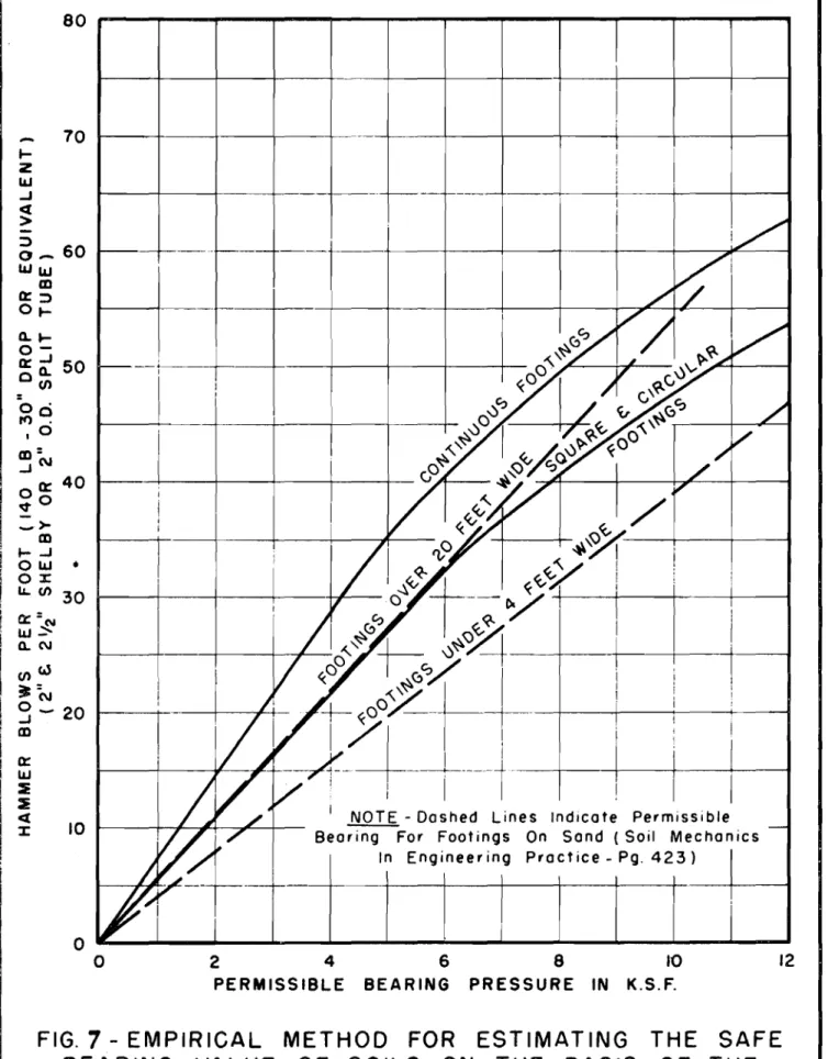
7
Empirical Method for Estimating the SafeBearing Value of Soils on the Basis of
II
-Page No.
Section
5
The Swedish Steel Foil Samplerby NoD. Lea
34
Fig. 1 Sketch showing Principle of New
Sampler (31)
Fig. 2 Sampler Head Model V
(38)
Pig.
3
Sampler Driven by Jetting with Water(39)
Fig.
4
Sampler Dri van by Jetting with DrillingFluid '40)
Section 7
Section
6
The Reclamation of Tidal Marshlands inthe Maritime Provinces of Canada by L.W. McCarthy
Soil Temperatures and Frost Penetration by C.B. Crawford
Session of January 11
47
Section
8
Heaving of Curling Ice Sheetsby B.B. Torchinsky
51
Ss:otion 9 SoilS and FOWldation Work in Manitoba
by A.Eo Macdonald
54
Seotion 10 FOWldation Invest.l.gation in Winnipeg
Following the 1950 Red River Flood
by Ao Baracos
56
Section 11 Resistivity Methods of Soil Exploration
by SoB. Sinclair
59
Section 12 Soil Description» Classification, and
Symbols. Discussion led by R. Peterson 61
Sectien
13
The Neutron Moisture Meterby BoB. Torchinsky
64
Sectlon
14
General Remarks and Business67
Appendix A - List of Those Present at the Fifth Annual Canadian Soil Mechanics Conference
Appendlx B - Third International Conference on Soil Mechanics and Foundation Engineering,
PROCEEDINGS OF THE FIFTH ANNUAL CANADIAN
. SOIL MECHANICS CONFERENCE
Foreword
This is the record
or
a Conference ofm\Jst
or
the active Canadian workers in the rield .of soil mechanics, held in the Seminar Room of
the Montreal Road Laboratories
or
the NationalResearch Councilor Canada, in Ottawa on January 10
and II,
1952,
under the auspices of the AssociateCommittee on Soil and Snow Mechanicso About 70
persons were present rrom various parts
or
Canadato take part in general discussions relating to problems in soil me chanics and to hear talks on
allied sUbjectso A list
or
those attending isincluded as Appendix A
or
these Proceedings.As proposed at the start
or
the Conference,the rirst day was devoted to the presentation of
papers and reports while the second day was reserved for discussion on problems of general interest and
business matters
or
the Conrerenoeo The materialcontained in Section 2 to Section 7 was presented
2 -sセ、sion
OF JANUARY 10. 1952
Section
1Introductory Remarks
by
R.
FoLegget
Mr.
Legget served as Chairman to open the meeting.
He
welcomed the delegates to the Fifth Annual Canadian Soil Mechanics
Conference and outlined the character and procedure of these
meetings.
He ment10ned that the conferences were sponsored by the
Associate Committee on Soil and Snow Mechanics of the National
Research Council, to encourage
、Qsセオウウゥッョand exchange of ideas in
t he
f1eld of soil mechanics and foundation engineering.
Although this was the fourth such meeting hei.d in Ottawa,
he hoped that future
gathemngs might be held elsewhere according
to the wishes of the delegates.
He looked forward to the next
meeting which might take place 1n Ottawa since in all likelihood
it would be possible
tohave this meeting in the new building for
the Division of Building Research, at present under construction.
He said that since these meetings were primarily intended to be
technical and time was limited, he would open the meeting oy
calling on Mr. Schriever to present the first prepared talk'.
- 3 ..
Section 2Toronto Subway Research
by
W. Ro Schrie ver
Mr.
Schriever's talk was divided into three sections: first, the necessity for and layout of the subway; second,construction procedure; and third, research on the construction project.
Necessity ar,d Layout
Toronto is situated on the north shore of Lake Ontario with its business section near the lake. Owing to its location the City extend;'; north, east and west to a greater extent than a city of comp ar-a-Te size not restricted in this way. The traffic flow is mainly L. two directions, parallel and at right angles to the shore of theJ-ake. The gre atest need for a subway is in the direction ;:.f gr-es: est traffic flow combined with greatest
congeet Lon , i. e. a' right angle s to the lake and therefore, of the two subways planned at the present time, the one in this direction along Yonge Street 1s being built first. It can be divided into three main sections corresponding to land values, of which the first in the business part of the City is built directly under Yonge セエイ・・エL the second on a private right-of-way oft Yonge セエN but underground, and the third in open cuts with city streets
」イッウウゥョセ the subway on bridges. Construction Procedure
The question has often been asked Why the subway was not tunnelled without disr pting street traffic in the business district of the city. In order to facilitate the transfer of passengers
from the surface transp rtation system to the subway and vice versa, it is desirable to construct a subway as shallow as possible and therefore tunnelling is impracticable. The construction method in which a subway .s built from the surface in a deep cut covered by
a temporary street deck is known as the cut-and-cover method, and this was used in Toronto. It consists of driving steel H-piles into the ground along both sides of the street at
6-
to 8-foot intervals. These so-called soldier piles which are driven below subgrade level serve to support the sides ot the excavation as well as the vertical 10ads of the traffic and the temporary street deck. The street is then excavated between the rows of piles to a depth of approximately 10 teet and a temporary deck consisting of acombination of steel and エセセ「・イ beams is placed over the excavation. Normal street traffic is esumed and further excavation as well as the construction of the actual subway structure is carried outi
4
-is backfilled with sand, the street deck removed, and pavement laid. Apart from a small area in the business section, where bedrock is encountered at depths from 20 to 40 feet, the subway is founded in soils of various types. Glacial tills and interglacial
sands and silts are predominant. Research on the Construction Proj!£!
As the construction of the subway is providing an unusual opportunity to investigate soil and foundation conditions along a continuous section through the City of Toronto and to study some related design and construction problems, it was decided to use this project as an "outdoor laboratory" for such investigations. The Division of Building Research of the National Research Council therefore approached the Toronto Transportation Commission and a cx-oper-at Ive research project was arranged. (The speaker expressed ィゥセ appreciation for the assistance given by the Toronto Transpor-tation Commission in conducting 'chis re ee ar-ch , )
The main research investigations are as follows:
(,) Investigation of soL. ccndi t.Lona and recording of the complete soil profile along the subway'
(2) Measurement of stresses in deck beams and other temporary steel structures;
(3)
Investigation of vibrations resulting from construction opera tions;1'4} Measurement of soil te1;'T,eratures.
In addition, several obher- smaller lnvestigations were
carried out and assistance given to the Toronto Transportation Cornmisslon in some special construction problemD.
The soil profile is bein; taken by recording soil sections at UPLセヲッqエ intervals, both fr::m an engineering and a geological
ー」\ゥョセZ of view. The geoLogf.cal, work is done in co-operation with a
」ッイョュゥエエセ・ formed of geologist interested in the Pleistocene geology of the area from the Univers:Lty and several ァLセカ・イョュ・ョエ departments. The soils are described in detail and the inf2rmation summarized on dra>,iings (of which an example was shown by thB speaker). It is hoped that this record will form a start on the ccllection of local soil records in Torontoo The soil ,:'rfile corroborated the
infor--atton obtained from borings c ar-ri e d out before c::nstruction tarted.
Dur"ng this workD soil sa"'ples were t akrn a' f:'equent
セョエ・イカ。ャウ and tested t the soils laboratory of the T:ronto Transpor-tation 'ommission for water:ontent, grain size distribution,
unccnf'Lned compressive st reng th, Atterberg limits, and other
5
-Many interesting soil problems were encountered during construction. Among these were the underpinning of buildings along both sides of the subway, the deflection of some of the soldier piles by large boulders contained in the till, the dewatering of part of the excavation by wellpoints and the
backfilling of the space between the sUbway and the street surface. The speaker illustrated some of the work by showing a number of slides.
Reports on various phases of the research work are in preparation.
Discussion
In reply to a question regarding the procedure followed when backfilling with sand around the completed subway structure,
Mr.
セ」ィイゥ・カ・イ said that during construction operations it was desirable that the deck should be left in operation as long as possible. Water was therefore used to compact the sand as it was not possible to use heavy equipment in the restricted space underthe decko The drains of the subway handled most of the excess water.
Mro Knight aske d if the volume of timber in the deck were known0 Mr. Schriever said he did not know the exact figure
but mentioned that the 12- by 12-inch timbers had been shipped via the Panama Canal. The Chairman said he thought that it would be about SセoooLooo board feet.
Mr.
Hall asked if vibrations due to pile driving close to existing buildings were recorded and if any relationshipbetween factors had been .::. stablished. Mr. Schriever said that a Leet portable seismograph had been used to record vibrationsg
caused both by pile driving and streetcar traffic. These records had been taken so that a comparison could be ma,e\e; the results were not yet analysed. In the measureme.nts emphasis was placed on a
determination of the rate of decrease of カゥ「イ。エMセッョ with distance and depth.
The Chairman mentioned that the reports on
Mr.
Schriever's work would be somewhat delayed as the work was being done ヲセLイ the Toronto Transportation Commiss on. He said tha there was a scarcity of literature available on vibrations due to pi:e driving but one Belgian paper had been discovered, ッオエャゥョゥセァ such work on a tunnel under a river.Mr. Coates asked about the order of m"gnitude of the impact factor on the deck beams. Mro :::>chriever said that at one intersection the impact factor was around
30
per cent for one vehicle (streetcar), but far less for a combination of veh cleso6
-Mro Davis noted that further from the downtown area in Toronto the water table was highero He asked if this had caused any damage or if the buildings had been underpinned previous to operations. In reply to this, Mro Schriever said that the water
table was not so much higher as more noticeable because the soil was more permeableo He said that settlement due to a lowering of the groundwater table in sandy soils was slight and did not cause any damage. He mentioned that most of the buildings along the subway had been underpinned.
.. 7 ..
Section 3
Recent Soil Mechanics Studies of the pセfセrNaN
by
rセ Peterson
Mr. Peterson said that as the proceedings of earlier
conferences contained an outline of the activities and the equipment of the PoF.R.Ao Soil Mechanics Division, his report to this meeting would only include an outline of some recent studies that might be of int erest.
Proposed South セ。ウォ。エセィ・キ。ョ River Dam
The dam ?s proposed is an e aztih fill 210 feet high and containing appr0ximately 35,000,000 cubic yards of fill. The valley at river level is approximately 2000 ヲ・セエ wide and the foundation consists of sand varyine; from a few fee' an depth near the edges of the valley to nearly 100 feet in depth at the centre. This sand in the valley bottom and the thin overburden on the abutments is
underla:.n by soft Be arpaw shale. The r-L: er sand and the shale are, t.her-e f'oz-ejl the t-;.,ro rna 'or materials to be considered where the dam
foundation is 」ッョ」・イョ・、セ
I. Bearpaw 3hale
The Bearpaw shale is of marine origin and is described as a clay shaleII al th'-u h many engineers woul d be more incline d to
regard it as a stift overconsolidated clay. It has been subjected to pressure of the キセゥァィエ of several thousand feet of sediment and ice in earlier timeso The water content varies from 35 per cent at the surface where it has softened, to a.,out 20 per cent in the firm unweathered material. The correspond ng range of wet density is 110 to 130 lb. per cubic foot. The Atterberg limits based on air drying are liquid limit of 110 and plastic limit of 20. The shale contains joints and slickensides.
Preliminary studies of this clay sha e have revealed many unusual prcperties and special tests have had '0 be devised to
evaluate these pr-oper-ttes ,
(a) Liquid lゥセゥエ Research
It soon became evident that the liquid limit test was very sensitive to the test procedure. In tests conducted at Harvard
University it was found that oven drying reduced the value of the liquid limit. On one sample the liquid limit varied as follows depending on the method: air dried, 160; natural water content,
=
8
-that routine tests indicated varia .. ions, led to a research program to determine the most practical procedure to be followed. In エィセウ
program the following variables have been studied while holding other variables constant: different operators, different machines, length of time of ウッ。ォゥョァセ ratio of amount of soaking water to
weight of soil sed, and size of particles before soaking. As a result of this study the tentative procedure is to air dry all shale to a moisture content of 4 to 6 per cent whereupon it is ground, passed through a No. 40 sieve, and soaked for a period of 24 hours. Several of the tests indicated that the variations were due to
incomplete soaking of the individual particles. It is therefore
proposed to extend the soaking period and to standardize the grinding procedure in an attempt to obtain more consistent results.
In conjunction with this program the swell test which is being used by the Bureau of Reclamation was studied. A fairly good correlation was obtained between the results of the swell test and the liquid limit but it was felt that the swell test required almost as much time and care as the liquid limit test. It was therefore decided to continue using the limit test.
(b) Consolidation Tests
Consolidation and swelling tests which have been carried out to determine the characteristics of the shale indicated very high swelling pressures. It was also evident from these that the
secondary time effect was very great in comparison with the primary. In view of this, special long time consolidation tests are being carried out. In one test a 4-inch diameter sample, 1 inch thick, was subjected to overburden pressure for a period of several weeks
and then subjected to a stress approximately equal to the weight of the dam. It is proposed to leave this stress on the sample for a period of at Least one year. A second sample of the same size has been set up and load ゥョセイ・ュ・ョエウ are being added at intervals of two weeks.
( c) She ar Tests
The shear strength of the shale, based on laboratory エ・ウエウセ
appears to be considerably greater than the shear strength computed from actual slides although the assumptions as to the depth of the sliding surfaces may be in error. The shale tends to soften at the surface and the presence f several zones of consistency has been ・ウエ。「ャゥウィ・、セ that ゥウセ ウッヲエセ medium and hard from the surface
downward. If the sliding planes occur mainly through the sdft surface shales, a better correlation exists between laboratory
strengths and strengths indicated by stability studies. Laboratory tests also give reduced strengths with increased time of loading Wlen the samples are held at c nstant water content.
(d) Slide s
In view of the doubtful va ue of laboratory shear tests in assessing stability prob ems, it has been decided to study na ural slopes and particularly those where movement has occurred. Based on
- 9 '"'
experience to date, a study or aerial photographs is by rar the best method of locating the boundaries or active slide areas. In addition,
!t is ne ce s aar-y to locate the slide surface and to study the material both above and below the slide surface. This has been done by means of bore holes, deep test pits and a test drift. Surprising as it may seem it is orten extremely dirficult to locate the surface of movement, particularly in material such as this which is jointed and slickensided. A careful study of water content profiles with determinations at inter-vals or 3 to 6 inches appears to be useful in locating slide surface. In an area where no sliding has occurred, the water content generally decreases unirormly with depth below the weathered zone. Where
sliding has occurred there generally is a very abrupt reduction in the water content prorile below the sliding surface. This would seem to lndicate that the material immediately above the slide surface has been reworked with the result that エィセG w ter content has increased. In addition to the water content ーイッヲセャ・ the consistency index has also been found to be very useful.
(e) Deep Test Pits
Test pits up to 160 feet deep ta7e been utilized in
connection with studies of the shale for purposes of examining the material in place and obtaining large uniisturbed samples for testing. It baa been found that safety precautions are extremely important
when working to this great depth.
The first experience with large 、ゥ。セ・エ・イ holes in the Bearpaw shale inv lved dri ling two 32-inch diameter holes with a well-boring machine0 These holes were put dOwn to depths of approxi=
セ。エ・ャケ 100 feet and were cribbed only throuqh the overburden, because it w s extremely difficult to carry the cribbing through the shale andt the same time withdraw the auger bucket. Jhis worked very well at first but drying soon occurred in the upper layers of the shale and chunks began to fall from the wall::. ᄋセヲ the bore hole0 On the advice of the consulting geo Logdst , these two holes were closed up and declared unsafeo The geologist also recommended that for any fu ure borings the PoF.R.A" work closely ",;1th the frovincial Mines d・ー。イエセョエN The Mines Branch has been most co=operative in working with the PoF.R.AG to develop a safe and practical method for excsvat ton of deep test pits0
The present method is to use wooden cribbing through the overburden. This cribbing generally consists of SMゥョ」セZ material and the outside dimensions are either
3
by5
feet or 4 by 4 feet.セエ。イエゥョァ at the surface of the shale, 48-inch diamBter l4-gauge
liner plate is used. Each liner plate ring 」ッョウゥセエウ of four ウ・ァュ・セエウL
the width of each ring being 18 Lnche; , Alternately with the liner
ーャセエ・ rings, 18-inch spacer bars b cked with wire ュ・セィ are used.
This makes it possible to examine the material through the wire mesh and where further samples are required" the mesh can \·e cut away and samples obtained. Both the wooden crib portion and t':e liner pla',;e portion of the pit are divided into two sections by vertical
10
-other section is used for access ladders. One very important
requirement of the Mines Department was to limit the length of ladder to about 8 feetg successive ladders to be separated by landings, thus
making it impossible for a person to fall more than the distance between landings.
It has been found desirable to erect shacks approximately 10 by 12 feet over all pits for protection against the elements. At each pit head a lighting plant and hoisting equipment are utilized. The lighting plant serves also to supply power for an electric fan which provides ventilation to the bottom of the pit. Lighting and hoisting units are both gasoline driven and, in compliance with regulationsg are set approximately 50 feet from the pit head to
avoid the possibility of monoxide gas entering the shaft.
This method of exploration has proved to be extremely satisfactory and while the cost is admittedly high, it provides an excellent opportunity to examine the material in place. The only
difficulty encountered to date has been where seepage water occurs on the contact or in the weathered zone of the shale" Attempts are being made to develop a satisfactory seal. All excavation to date has been by hand methods although air tools would increase the excavation rate.
(f) Pressure Test Section
The pイッセ・・、ゥョァウ of the 1950 Soil Mechanics Conference, Technical Memorandum No. 19, contain a brief description of the test drift in the shale Rt this damsite and mention is made of セ pressure section to measure the vertical and horizontal force exerted on a continuous lining by the shale. The details of the pressure test section an d the test drift are contained in P.F.R.A. イセセーッイエ entitled "Geological Test Driftg Damsite No. 1011 De cember-, 1951. The following
covers a brief description of the pressure test section along with the readings which have been recorded to date.
The pressure test section is located at the end of the drift and consists of a 20-ioot length lined with pracast concrete slabs. The slabs are 2 feet widell 8 inches thick and approximately
6 feet long. The horizontal and vertical slabs are staggered so that the joint be twec n two horizontal slabs falls at the centre of a vertical slab. Each pair of opposite slabs are held in place by pipe struts provided with a screw jack. A pair of horizontal struts are used to hold two oppo sLte vertical slabs and a pair of vertical struts to hold two o:::posite horizontal slabs. The excavation and the placing of the slabs was carried on continuously and it was
エィ・イ・ヲッセ・ possible to make the entire installation in a period of 10 days. Dry packed grout was used to backfill the irregular space between the back of the slabs and the mined surface of the shale. When the installation was completed a predetermined pressure was
applied through the screw jacks onto the slabso Initially a load
approximately equal to 130 per cent of the overburden stress
(overburden above drift,
64
feet) was applied to both the horizontal and vertical slabs. The screw jacks were left unchanged and load... 11 ..
readings taken pBriodicallyo The load tended to drop off on both the verti:::'l and hcr-raont el slabs for a period of about three months and then began to increase very slightlyo The present load on the vertical struts is approximately equal to overburden and -the present load on, the horizontal struts is approximately equal to the initial applied loado It would therefore appear as was originally ウオウー・」エ・、セ
that the horizontal atress in this heavily pre consolidated shale is greater than the vertical and that such a stress distribution might be expected upon a tunnel lining.
The load in each strut is determined by means of strain measurements utilizing a 20-inch Berry strain gauge. Initially all
40
struts were calibrated in the laboratory and stress-strain curves determinedo hッキ・カ・イセ during the course of the readings it hasbecome evident that there are some 'errors in this system» believed at present to be less than 10 per cento In the near futurel) howeve rl) it is proposed t o r-e chec k the calibration of each strut by t empor-a-rily reducing the load to zero. It will then be possible to appraise the accuracy of the me rhod being used.
2. Hi ver Sand
Preliminary sampling indica"ed that the river sand was fine to medium grained with a DIO of 0012
mm.g
a D60 of 0030 mmo and a coefficient of uniformity of 2.5. The majorIty of these disturbed samples were recovered by means of a bailer and it way felt that the .gr-sf,n size d.':..stribution was reasonably accurate9 basedon a few tube samples taken as a checko However, no information on stratification or density was obtiafneJ,
(a) Cone Bearing Tests
In order to obtain some information on the relative density of the sand in pLace , a bearing cone (described in "Soil Mechanics in Engineering Practice" by Terzaghi and Pe ck , Figure l2lcl) Page 216 was used. This cone was calibrated in the laboratory and also in a
sand deposit above the water r ab.Le in the fieldo The purpose of the calibration was to obtain an approximate relation be tween 1:'e sis-tance to penetration and de nsttry of the sand. Following t.hrs , tests were carried out in the river sand w::1ch indica:.:ed that the aand o-as
at a density near the boundary between the Lee a- and medium dense states0
(b) Undisturbed Sand Samples
Undistur'::ed samples ,cf the sand were desired to determine the density and observe stratificationo Howeve, it was recognized that this would be extremely difficult because the material is be ow the キ。セ・イ table. セッュ・ thought was セゥカ・ョ to using the frozen plug method which had been develop·d by the Providence District of the U.S. Corps of Engineers. HOWBverp this was never carried out because
12
-The U.S. Waterways Experiment Station has re:ently deve·' loped another mer.hod for recovering undisturbed ,,:and samples below
.he water table. Thls is described in Bulletin No. 35 of the
Station entitled "Unrf.s t.ur-be d Sand Samples Below the -..Jater Table". It involves drilling a 5-1nch diameter hole using rotary equipment
and a heavy drilling mud to prevent caving of the hole. Great care
is also taken to use slew rotational speeds and avoid loosening or
dLscur-b Lng the material by strong jets of water. The actual samples
are recovered using a 3-inch Shelby tube sampler fitted with the standard piston and it is the general practice to recover practical=
ly continuous core samples. It has been found that the drilling mud
penetrates only a very short distance into the sand. Where it is
desired t, obtain the density of the sand in pi ace , the sample
tubesll which are originally about 36 inches longll are stored in a
horizontal position and cut into 3-inch lengths and the sand density
in each length determined. Where it is desirable to study
stratifi-cation the s-mpI.e tubes are stored in a vertical position and cut
longitudinally so that the stratification can be st.died in detail. It was found that a metal band saw was the most sat ...sfactory for
cutting the tubes. The P.F.R,A. organization has now acquired this
method and one hole has already been driven and the ,!amples are now
in the process of being examined. While the method ..s quite slow
it appears to be entirely satisfac';ory. Cc) Pumping Tests
The permeability of the river sand is ゥューッイエ。ョセG in deter=
mining the type of seepage control to be used with the dam. A
number of pumping tests have therefore been carried out, The
earlier tests invol v/d use of an ordinary weI" point witl> 80-tllesh
screen placed a a depth of 4 or 5 feet with eight obae r-vabLon
wells placed on two lines at right angles. Following thisll a
slightly more ·;'lr borate test was conduct e c with a centra} well 3
inches in diameter extending to a dpth of about 20 fe:,1:;:o More
recentlY an 8=inch weL.. extending to a de:th of 50 feet ,,;ith 22
observation wells has been used. The average k for all types of
tests was 0014 foot per minute with no indications of variations
with depth.
( d) St" '.' Sheet Pili'S Tests
In the d,sign studies of the proposed dam, methods of
seepage control he,: were considered included steel sheet pilingll
an upstream blanket and 8. positive trench=type cutofi' tl;J shale.
The studies revealed that the positive trench type cutoi'f WaS
very costlyII diffic:,jl t to construct and probably unne ce s sar-y, The
choiceD thereforell had to be made between steel sheet piling and
an upstream blanket or both.
In order エセI obtain mere information on the effe: tiveness
of steel sheet piling in controlling seepageII a series :::1' tests
were conducted using カ。イゥッセウ sections of sheet piling and typical
river sand. The flow of water エセイッオァィ the sheet piling interlocks
was measured along with the corresponding drop in pre ss: re: for
- 13 ..,
flow due to the sheet pile wall has been pr-e dd c be d , The details of these tests are contained in a P.F"R"A" report entitled "Steel
Sheet Piling Studies" Decemben, 1951. On the basis or the studies it was concluded that unless rustingll 」ッイイッウゥッョセ。ョ、 air locking
occurred in the piling beneath the damll that a relatively short
length or blanket was as efrective and much more economical than steel sheet piling. The base of the dam as now proposed is approxi-mately 2600 reet wide with a rilter drain extending into the rill
about 1000 feet rrom the downstream toe" If steel sheet piling were used it would be placed at about the upstream quarter point. Studies were made to determine the length or blanket which would be equivalent to steel sheet piling placed at this point.
It should be mentioned that several types of arch piling were studied but all behaved in the same general manner from the standpoint or seepage. There was!> however» considerable variation depending upon whether the joints were loose cr tight. Based on a coefricient or permeability of river sand of 0.14 foot per minute and a head of 190 f'e et , it was estimated that the seepage be ne abl. the dam with no piling or n: blanket would be
31
cubic fee,. persecond. Using the. same assumptions mentioned above and sneet piling with the interlocks loose but filled with sands the seepage wad
calculated to be 30 cubic feet per second. An upstream blanket 33
feet long would cause a similar reduction in rlow. Using the assump= tions mentioned above and the interlocks tight and filled with sandg
it was calculated that the seepage would be reduced to
28
cubic feet per second , A blanket having a length or about 145 feet would cause a similar reduction. It is quite obv rous , the r-ero r-e, that unless the sheet piling corrodes or air locksll that it is relativelyineffective.
The present proposal is to use a blanket about 1200 feet in length!> which according to calculations will reduce the seepage to the order of 18 cubic reet per second. It:.s felt that natural silting in the reservoir will p within a very short space of timeg
reduce the seepage to a small fraction of the flow experienced when the dam is initia:ly 」セョウエイオ」エ・、N It is also proposed to use
drainage wells to provide relief at the downstream toe of the dam. St. Mary Dam
The sto f\'lary Dam has now been completed and during the past year the reservoir has been almost full for a short period. Some seepage has ッセ」オイイ・、 through bedrock in the abutments and a grouting program to cut this off is nearly completed.
The test apparatus which was installed in this dam has provided very interesting data. From the soil mechanics point or
view the impervious central section of the damp which was construc= ted of glacial clay having a liquid limit of
35
and a plasticity index of 149 is by far the most interesting. This material was placed in 6-inch lifts and compacted by 12 passes of a sheepsroot roller exerting unit ーイ・ウウオイ・セ of about500
pounds per square inch. A deliberate attempt 'HaS made to compact the m;qterial slightly on<=
14
<=the dry side of the optimum moisture content for field compaction and several per cent below the Proctor optimum in order to avoid the danger of future pore water pressureso Standard Proctor tests
indicated an optimum moisture content of 15 per cent at a dry density of
114
Ib o per cubic footo The average dry density asplaced was about 110 Ibo per cubic foot at a water content of 12 to
14
per cent o .The Bureau of Reclamation type settlement gauges have revealed that the total compression within the impervious section with a height of 200 feet is now of the order of 8 feet and consoli-dation is still going on at a reduced rateo However, in spite of this relatively high settlement there has been no indication of pore pressureD which is attributable to the fact that the water content during compaction was kept as low as possible without causing serious reduction in density as placedo It is calculated that the density in the lower layers of the fill has now increased to 120 lb o per cubic footo
Travers Dam
An earth fill dam of comparable volume to the St0 Mary Dam has been S" arted on the Little Bow Valley about
40
miles north of Lethbridge0 This dam is a unit in the Bow River Developmentdesigned to セイイゥァ。エ・ about 250DOOO acres in the area north and west of Medicine Hat D Alberta o The dam is 130 feet high and contains ab ut 4D500DOOO cubic yards of fillo
The fLl materials for this dam are ideally Locased ,
Impervious cl YD pervious sand and gravelp rock riprap and concrete
aggregate all being available within a one-mfL, radius of the dam,
The foundationp howeverp c nsists of Bearpaw shaleo In view of
the fact that some instability in the shale is evident in one
。「オセュ・ョエd the fill has been flared out at this abutment and fillets utilized between the dam and the abutment in ord":'r to completely srab lize any aor.e s that might tend to become unstable Wi.th ,;"ater
in the reservoiro Extensive test apparatus is being Lnst.al Leo to
record the behaviour of the structure and to obtdn further information on the behaviour of the Bearpaw snaleo
Canal and Dugout Lining Program
The Po "'oRcA o is carrying out an e xtenaz.ve experimental progtt:"m on canal and dugout lining me thod s , The First Progress Report, covering this investigation was pr-epar-ed, Ln Marchp 19510
Since this Progress Report was pr-epare d , experimental installations of everal other types of lining have been tried o These involved bentonitic material sluiced into waterp prefabricated asphalt
ュセュエイ。ョ・Y and catalytically blown asphalt sprayed on to a prepared aggrBgate baseo Based on the studies to date it would appear that where suitable materials are available locally a compacted clay lin_ng about 12:nche s thick and covered with abcur 12 inches
ot
FIFTH CANADIAN SOIL MECHANICS CONFERENCE N.R.C. - OTTAWA - JAN. 10-11, 1952
R. Peterson - P.F.R.A.
PROPOSED SOUTH SASK. RIVER DAM
セイー。キ .sna/e
1. Bearpaw Shale - overconsolidated stirr clay Water content range - 20% - 35%
Wet density - III - 130 lb. per cu. rt. Liquid limit - 110, Plastic limit - 20
(a) Atterberg limit research - values arrected by drying
(b) Shear tests - may not rerlect true strength
(c) Consolidation tests - secondary time errect great
(d) Slides - located by air pbotos
- slide surrace rrom water content proriles
(e) Deep test pits - up to 160' - sarety precautions very
important. '0'"." ImerーO。セ 14gage L-l セM 111'_ X'5 M Spa • ...
:;:::
L.. C.
.
セ r/ x -L-A K;yセ セ
(r) Pre ssure Test Section - "Geological Te st Drirt Damsi te No. 10"
- P.F.R.A. Report April, 1951
r
=
soil densityb
=
deptb or coverUnit Stress
Vert.
=
ViA
Horiz=H!A
Ini tial 1.26'( b 1.32 'fb Minimum 0.99 セ h 1.21 'd'b Present 1.05セ「 1.J4l'h
-r'セ ZLGセN . ' • • • . • : 4 ·":[ 4",'."t GNセZ.
j.
fnセ GZセZ セ<..
-+--s,,!.- ...
, \ セ[Lセ Nセ Nセ , >"..
セ セG -';'.セ|
IHI. Zセセセl-T
:-; ,セZセG
.
'-,.
'..
-'.-",'.'.,',;;'}." セ A=
ar-ea or slab Vl+V2=v
HI+H2=
H2. River Sand - fine to medium, DIO
=
.12, D60=
.30, Cu=
2.5 ( a) (b) ( 0 ) ( d) 61DrtKef --- - - - MGイZBBWMMイセCone bearing tests indioated loose to medium density
state - see Terzaghi &Peok, Fig. 1210, p. 276.
Undisturbed sand samples - using Vioksburg method - see "Undisturbed Sand Samples bf'low the Water Table",
Bulletin No. 35, uNsNwNeNsNセ Vicksburg, Miss.
Pumping Tests - Average K
=
oNャセ ft. per min.Steel セィ・・エ Piling Tests - see 'Steel Sheet Piling
Studies", P.F.R.A. report, Deoember,
1951-(i) Cross Section of Proposed Dam
Hor J'C'./t: I ' ·.4DO'
rer. ocate ,', eoo '
RIver ' Sand
セOOOャAZyOセODWOsOjNᄋヲMOOコZNM
BGィセ・ヲ Pdm9'
(ii) Flow-Permeability Diagram for above Cross Seotion
40セMMMMKMMMMMMKMMMMMMヲMMMMMLセセ No piliflJ) 0 Blank.et .30 IV/th pt'lin J iii
"
I.i I '10 セ セ セ,
/0 Blanket ler'jth e'luiva/ttmt to sheet pi!!tTJ' (for k= 0·/-1 Ft.f'er. min. only)
.05 ./0 ./'S .20
Permeahl/itJ -{ R. ver: 5'and - K - ft. per. min.
For K
=
0.14 ft. per min.:(A) Q
=
)1 c.f.s. (no piling, no blanket)(B) Interlocks loose, sand in interlocks loosely plaoed, with "k" approx. 0.09 ft. per min.
Q
=
30 c.f.s.Blanket length, equivalent to piling
=
33 feet(C) Interlooks hand-ti§ht, ウ。セ、 in interlocks
hand-tamped, with k" appr-cx, 0.02 ft. per min.
Q = 28 c.f.s.
17
-DiscussionReferring to the vertical and horizontal pressures measured in the test drift for the South Saskatchewan River Dam, Dean Hardy commented that he thought it would be misleading to quote them as a percentage of the overburden and thought it should be overburden pressure plus the swelling pressure.
In reply,
Mr.
Peterson said that because there was very little movement of the shale, it was difficult to segregate between "swelling" and "pressure". The material was not highly swelling but developed high pressures. The measured yield into openings was very low and so the material was not considered to be a swelling shale. The "no yield" pressure wae that which was sought in the test drift.Dean Hardy asked, assuming that the present pressure is constant, if Mr. Peterson expected to get an increase of
34
per cent of the horizontal pressure over the ovez-bur-den pressure at anydepth.
Mr.
Peterson replied that he thought it would vary to a minor degree.Regarding the St. Mary Dam, Dean Hardy said that it was interesting to note that 8 feet of settlement had been recorded, in sp f;e of the fact that this was at a smaller pressure than that used in compaction. He wondered if this was because the load was present over a long period of time.
Mr. Peterson said that approximately 6 of the
8
feet of settlement preViously mentioned were rapid settlement due tocompre asLon of the air voids of the unsaturated soil and took place during 」ッョウエイオ」エゥッョセ the remaining 2 feet of settlement キセイ・ caused by consolidation owing to air and water escaping from the vr:id.s. Mr. Peterson said, in reply to Deffil Hardy 5 question, that they were not considering using lighter rollers.
Mr. Knight asked if sections of the deep test pits had
been checked to see if clay was creeping ゥGセL on the mesh. Mr. Peterson said that most of the "creeping" was due to spaTling; no bUlging
occurred. Mr. Peterson explained thst the d '.sturbed materLd t:c:','.ame wet and then moved.
Mr. Coates asked if chemi a:" g r-outLng <W';51S economically
feaslb. e for cr-ear In.; sand cutoffs. MC'. P;,.;te!'sor:. said that the:! were follOWing pr-oce cur-e s used in th:6 U.n.ite3d States on the Missouri Rive"" where the mate,ial is simila' tor:hat in Saskatchewan and that the possibility
or
chemical gr:,ut rng }:'",d not been eugge sbe.t ,Mr. Ooace s mentioned work .,.': had beeD.jone in the San Pr-ancLsco are a to make soils ゥュー・イュGLセ .'Able by chemical meansII as
repor-bsd by Mr. C. Ho Lee in the Tr.iJ:lsafjtiona of the American SocIety of Civil Engineers" Vol. l06s ー。ァセ
57
7 , in1941.
18
-Mr. Fairbairn mentioned that timber cutoffs such as Wakefield piling were used in the Province of Quebec and asked i f
this had been considered at the South Saskatchewan site. Mr. Peters n said that wood piling was not considered since the necessary depths were too great and many boulders were present.
Mr. Peckover asked about the formation of slickensides in the Bearpaw shale. Mr. Peterson said there were various opinions on this.
Dr.
Terzaghi thought that slickensides were caused by chemical changes in the shale, whereas Dr. Casagrande WAS inclinedto think that they were caused by internal adjustments when the overconsolidating load was removed and the brittle shale had a tendency to pop up.
19
-セ・」エゥッョ
4
Deep Sounding Methods for Evaluating the Bearing Capacity of Foundations on 50il
by W.. A.. Trow
In recent years considerable attention has been given to the use of apparatus for measuring the strength of soil in place. There are good reasons for this attention. It is felt that a more accurate measure of the soil's capacity is obtained by field tests because disturbance of the soil is rc duced to a minimum. It can lower the cost セヲ major foundation investigations by reducing the number of expensive borings required. For this reason it should permit a more thorough foundation investigation to be made.
In recent years several methods have been developed for estimating the capacity of soil in place. Of these the following three devices have received the most attention: the rotating vane or Swedish auger, the Dutch cone penetrometer, and the standard penetration test.
The rotating vane is a device consisting of four rectan-gular wings mounted at 90-degree intervals about a shaft. In order to indicate the shearing resistance of the soil it is forced into the ground to the depth at which measurements are to be made. It is then twisted slowly until the soil is sheared. Since the
twisting moment on the shaft required to cause this failur Is equal to the moment supplied by the resistance of the soil along
the failure surface of revolutionp the shear strength of the solI
can be calculated.
The vane was originally developed in England toward the end of the last war to provide means for indicating the capacity
of soils to support tracked vehicles. It was also used by Swedish engineers for evaluating the capacity of foundations.
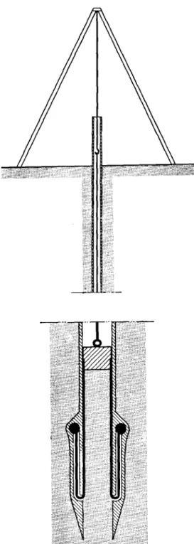
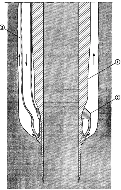
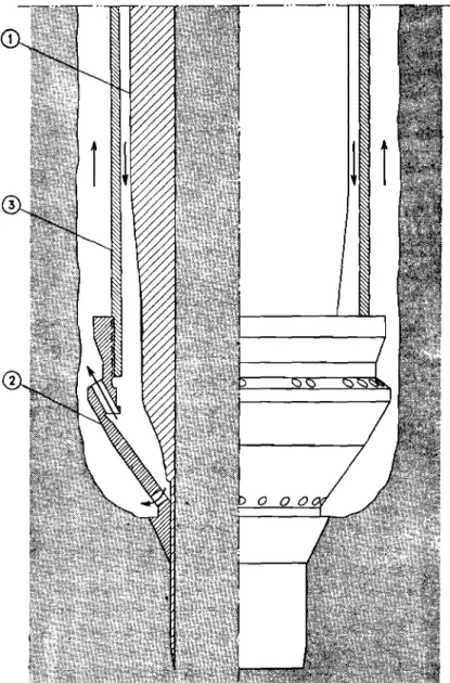
The cone penetrometer is essentially a small footing that is forced into the ground until the resistance of the so 1 is overcome. It consists of a 60-degree cone approximately
Ii
inches in diameter at the base. It is connected by a thin steel shaft to an oil 'ylinder fitted with a gauge calibrated in soil bearing pressure units. The load transmitted through the cylinder to thecone is weasured on the gauge. Soil friction on the steel shaft is preveted by placing it inside a steel casing. This apparatus is widely used in the low countries of Europe to locate strata of suitable-earing for supporting piles.
The standard penetration test is an empirical method for evaluating the capacity of foundations on sand. The c ap ac I ty of the sand is measured by driving a split-tube sampler, 30 inches
long and 2 inches in outside diameter, 12 inches into the soil under the blow. of a l40-pound hammer freely fIling a height of 30 inches.
= 20 =
Initial calibrations of this test with field loading tests permitted a chart of hammer blows versus safe bearing values for granular soils to be developedo The test is not recommended for use in sensitive clays soils but there is reason to believe it may be a useful test in some of the leaner clays and glacial till soilso
The Ontario Hydro=Electric Power Commission was particu= larly interested in deep sounding equipment because of the large number of foundation investigations required during recent expansion activitieso It was hoped that the equipment could be used to
evaluate foundation conditions for transmission tower footingso As a イオャ・セ work schedules for tower line construction do not permit
thorough foundation analyses to be madeo Occas10nally this ignorance of soil conditions results in costly delayso It was felt that a
solution to the problem might be supplied by vane or cone testso With this in mind a program was initiated to study the accuracy and limitations of the vane and the cone0 Several field
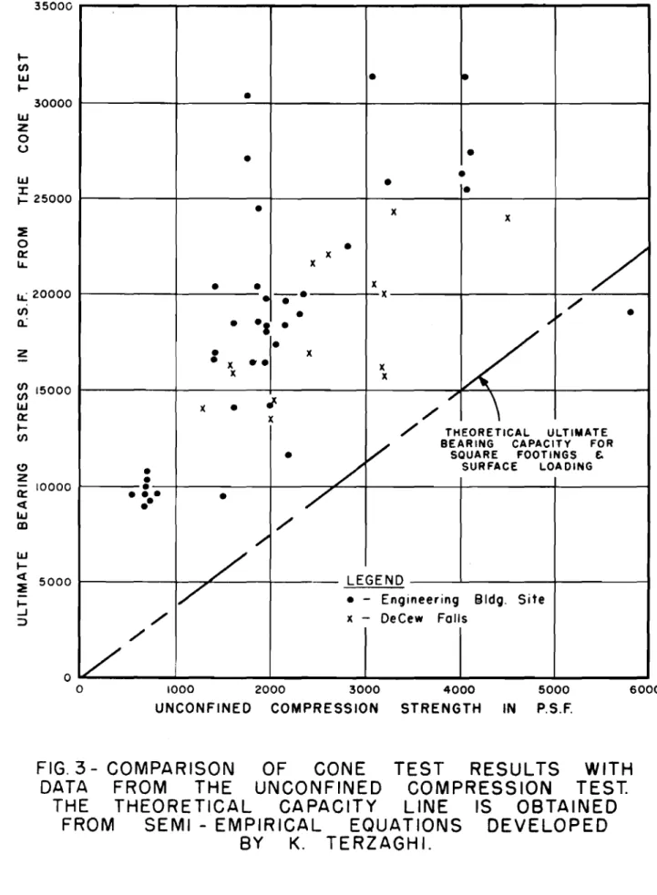
measurements were made with these devices and the results compared with the laboratory unconfined compression testo The cone penetro-meter used was the relatively flimsy model shown in Figo lQ Experi= ence with it was to govern the decision regarding purchase of a more rugged modelo A limited number of tests in clay soil were made with
this device and after each test an undisturbed sample of soil was obtainedo Each sample was subjected to the unconfined compression
t e at , following which the ultimate bearing cap::city of the soil was calculated using t・イコ。ァィゥセウ formulao A comparison between the two methods for measuring soil capacity is shown in Figo
30
It will be observed that most of the points lie above the theoretical capacity indicated by soil mechanics theoryo This is not considered a fault because theoretical formulae have often been suspected of under= estimating soil capacityo Although there is some scattering ofindividual points on the chart it is by no means extreme when one considers the factors that an influence measurements of soil ーイッー・イセ
tieso Unfortunately the apparatus purchased was not robust enough for the soils encountered and plans are under way to obtain a
sturdier rigc This comparison was made ror clay soils onlyo A sturdier rig will permit tests to be made on granular soilso
Enthusiasm for subsoil measuring devices centred around the vane apparatus0 This interest prompted the incorporation of
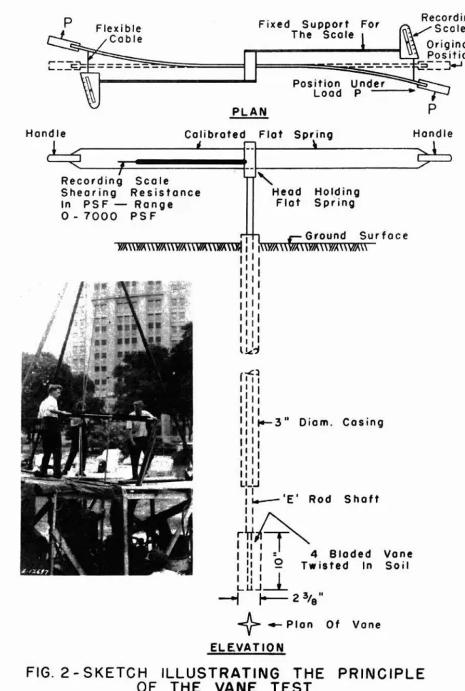
sever 1 modifications in the machineD some of which are of questionable merit The principle of operation is illustrated in Figo 20 Stress is applied to the soil by rotating a 4=bladed vane 2
3/8
inches in diameter and 10 inches longo The rate of rotation must be very slow t avoid generating a temporarily hi h solI イ・セゥウエ。ョ」・ッ In passingp it is understood that a height=diameter ratio of 2 is preferred for a vane0 The vane is connected by means of standard drill r-ods to acalibrated flat spring equipped with handleso Torque applied through the spring to the vane caus s the rider on each scale to move and indicate loado Each scale has been calibrated to indicate shearing resistance of the soil directlyo This was done on the basis of the formulag
S = M (max)
セョRh + un3
( 2 6 )
21 ..,
pounds per square foot
where M (max)
=
Maximum turning moment . ppled to van: in f ..::,ot pounds D = diameter of vane in teetgH
=
height of vane in feetoThe calibration assume s that the re ist:ng ヲHセイ」・ of the soil acts along the s trface of revolution of he vane at. a mome.rt arm o n/2 from the centre of the shaft0 Subsequent tests Z。カセ cast
doubt on this suppositiono As in the 」。セ・ of the Dutch conep soil
friction on the shaft is avoided by placing the drill rOi's inside a 3..,1nch casingo
Figure 4 shows a comparison of the shearing resistance of everal soils determined by the vane and by the unconfined
c mpression testo Most of the tests were made r.t a depth of 3 セ・・エ
below the surface0 ThL= was done to avoid any :ossible Lnf Luerice of depth on the soil strengtho Experience with ormally loaded
clays suggests that their strengt- should increase with depbh , Although the vane measures this increaseg the Ibor ... tory test
frequently does not イ・ァゥセエ・イ ito
If both tests supplied accurate measurements of the shear strength of the soil all points snout : lie along the Tsセ、・ァイ・・ line shown0 Since the laboratory test is f':"equently suspected of underesti=
mating the strength of soi).s one might expect the average,f the points to lie somewhat above the 4S..,degree line0 This co··dition d,-:es exist
but the extreme scattering of the data 10es not permit a relationship between the two tests to be e stabl :":.shed o
There are possibly two explanations for this poor agreement0
One is that the samples for the unconfined compres:::ion test were so disturbed that they g reatl: underestimated the strength of the soil. Some disturbance during sampling is inevitable bu : it is unlikely to influence the results to this degree0 The Commi:osion is aware
of the conditions that can produce poor samples an . reasonable care is exercised to avoid themo The second explanation seems to be more reasonable. This 1s that the centre of the イ・ウゥウセゥョァ forces in the soil is not located along the surface of revolution of the vane but at some other position· far her out from the centre of the shaft0
If this is SOg a given resisting moment to the rotat;on of the vane
can be generated by a smaller shearjng resistance in the soLt, In other words a long8r lever arm :s availa0le to the resisting forceso
Values lor the shear,trengths were supplied .from the
unconfined compression test on samples taken 4 feet below the surfac80
This method of calibration is n: t very ウセIエゥウヲ。ッエッイケ i t the soil properties are different at gre ter depthso
22
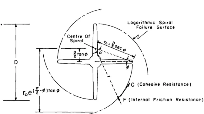
-Figure
5
shows a conception of soil failure around a vane which might offer a method of interpreting the results of the vane testo This method assumes that the soil fails along logarithmic spirals having the equationr
=
roee
tan (JWhere r is the radius from the centre of the spiral to any point on the curve;
r o is the radius from the centre of the spiral to the tip of' the vane;
e
is the angle in radians through which the arc moves from the tip of the vane to any point on the arc; andセ is the angle of internal friction of the ao I l ,
The centre of the spiral is located on a straight line making an angle
¢
with the vane blade. This permits the arc toleave the vane blade at right angl.e a,
Resistance to rotation of the vane is supplied by the cohesion of the soil acting along the arc of failure and the
friction force F having a line of action through the centre of the spiralo Some approximate formulae were developed on the basis of this conception of failure which theoretically permit the use of
the vane in both granular and cohesive soilso
For purely cohesive soils this spiral becomes a circle having a diameter equal to the diameter of the v-ane. Force F then passes through the centre of the shaft and applies no resisting moment. In Fig.
4
which illustrates the comparison between the vane and unconfined compression test dat a, good agreement can be observed for medium and soft saturated clays having a shear strength up to 1000 pounds per square footo The angle of internal f'rictionof these clays was probably close to zero. Unfortunately circumstances did not permit triaxial tests to be made so the presence or absence of internal friction in the stiffer clays could not be confirmed.
Whatever may be the cause of the unsatisfactory demon= stration of the vane6 its value to the Commission as a simple tool
for measuring soil strength is considerably reduced. This is because it appears to require considerable correlation with other data before it can be interpreted. However6 it is felt that it
has its place in large foundation investigations where the soil profile and soil properties have been satisfactorily Astablished. Here it should reduce investigation costs and provide more knOWledge per dollar spent by disclosing possible differences in soil proper-ties between borings. There is also reason to believe that it is an easy method for measuring the sensitivity of soils and for indica-ting the stress-strain characteristics of the soil prior to failure.
- 2) =
In the search for a simple method for obtaining an approxi= mate measure of the capacity of the soil the Commission turned to the
standard penetration t e st , Desphe the fact that the test was primarily designed for granular ウッゥャウセ it has been noted during many foundation
investigations that the resistance to penetration of sampling equipment is a guide to the condition of all types of subsoilo
During the last
4
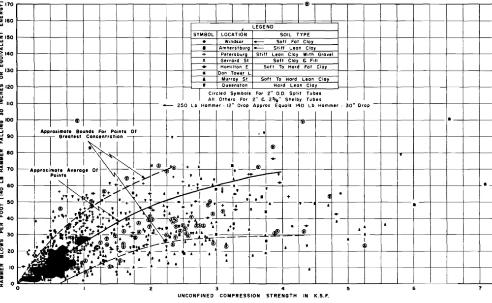
years well over a dozen major and minor foundation investigations have been conducted in the process of whichupwards of dOOO penetration and unconfined compression tests an clay soils alone were madeo In all of these tests the penetration resis= tance to the sampling tube followed the same trend with depth as the unconfined compression testo This held for 2-inch and 2 5t8=inch thin=walled Shelby tubes as well as with the thicker-walled split= tube samplerso Out of curiosity a plot was prepared of the unconfined compression test data versus the penetration resistance to see if
any trend could be established o The results of this compilation of data are indicated in Figo
60
The dark blotches on the chartrepresent points which were too densely packed to be clearly distin=
gul ahed ,
Although the relationship between the two tests is by no means well marked it is not altogether unsatisfactory when one considers the wide range of soils tested and the disappointments that beset soil me asur-emerrt a , The limits of the denser part of the data have been defined by two dashed Li.ne a, It is fe:t that many of the points above the upper dashed line represent tests on soils with low cohesive resistance and a high percentage of silt and
coarser soil particleso Points below the lower dashed line might well represen samples that have lost moisture before the unconfined test was made or conditions where wash water penetrated ahea; of the boring before the sampler was driven0
Altho gh the Commis ion is fUlly aware that this data
should not be u:ed for the tina design of important fo.ationsp it
is felt that me' _,urements of diving energy are an e xce Lzent guide in the appraisal of the c ap a cLt of so Ll s , This is e spe c LazLy so in the case of transmission tower footings where simplep approximate
test methods can be tolerated o With this in mind an arbitrary line was drawn throug the most dense concentration of p ofrrta , :'.:.-:1s
line represents the approximat relationship between the pene tir-atLon test data and the laboratory unconfined compression testo T line toward the upper dashed boundary line was purposely plotted cn order to insert a small factor of safety into the estimateo
Since the ultimate baring capacity of soils suppcrting square and continuous footings is approximatel!
307
and2085
times the unconfined compression strength respectively, this chart can be readily converted to indicate bearing capacityoBy applying a factor of safety of 3 a relationship of safe bearing capacity versus driving resistance in clay soils can be established a This is illustrated in Fig o
70
For comparative purposes this chart also contains safe bearing values for footings on sand Lnt e rpz-e t.ed from data in セQsッゥャ Mechanics in Engineering Practice" by Terzaghi and Pecka• 24
-In closing, what are considered to be the merits of the modified penetration test are summarizedo
(1) The test is as easy to carry out as other deep sounding
methods in glacial soils;
(2) it is a useful guide to the capacity of lean clays and
other cohesive soils of glacial origin;
(3)
it permits the recovery of soil samples while a soundingis being made;
(4) it serves the same purpose as any other sounding device
for probing for variations in soil conditions over a site; and
(5)
it should be suitable for minor footing designs such asfor tower footings where the time and expense of more complete analyses cannot be spared.
Discussion
The chairman stated that during the war, the Associate Committee on Soil and Snow Mechanics had investigated penetrometers for a particular purpose and had found that the state of stress in soil underneath a swnpler was a very complex one o
Mro Lea mentioned that his Company had developed a vane
apparatus which recorded a stress-strain diagram. He said that in
his e xper-Lence , the vane test gave approximately twice the value of
shear strength obtained by the unconfined compression test but this
ratio varied with soil types. He thought that there was a great
need for correlation Jf field penetration tests and of the results
obtained from them. He said that he had studied different types of
soil samplers and ィ。セ found the results of tests on Shelby tube
samples hard to inte"pret to obtain an indication of the cohesive strength of soil.
Referring to Fig o 6 in Mr. Trow's paper/) Dean Hardy thought that different curves w<uld be obtained for cach type of soil, often
varying widelyo He said that one soil type should be dealt with
alone and then other soils could be correlated against the one standard
result. Then a serie"} 0" curves would be obtained each of which would
apply to a certain so"l type.
Dean Hardy pointed out that it the standard penetration
test were used that a samyle should always be obtained. In this way"
one curve could be established for sand, one for Silty materials" and so on.
Mro Trow said that the figures he had given were just to enable field engineers to make an on-the-spot decision and that they
were never intended for accurate analyses. Mr. Trow said that
Dr. Terzaghi did not re'ommend the penetration test in sensitive clays"
but as most clays encourbeee d in Hydro work in Ontario were lean clays"
In discuss}on of Mro Trow's talk» Mro Fairbairn stated that Construction Borings Limited had used the vane borer for some years as a check on unconfined compression test and standard pene= tration test resultso Results were generally good in soft and cohesive materials where the vane test usually confirmed the unconfined compression resul tSD whereas the standard percussion
test indicated lower bearing values and shear strengths in these materialso ThisB of 」ッオセウ・AI was quite apart from the question of
settlement caused by consolidation of the soilo Mro Fairbairn said that the Company used the standard penetration test with the split spoon sampler in coarse sands and gravels9 and switched to
vane tests and Shelby tube samplers in cohesive materislso He
called the attention of those present to a reference (l)p concerning the vane borer where numerous experiences with the apparatus were reported9 along with comparative tests with cone penetrometers and
unconfined compression testso
Mro Torchinsky asked how the vane sampler was pushed into the soil and Mro Fairbairn replied that it depended on the type
ot
soilo Usually it could be pushed by handp but sometimes it wasnecessary to drive the vane with a hammero
Mro Schriever asked it the shearing resistance along the bottom plane of the vane contributed much to the total shearing resistanceo Mro Trow said that he thought no one could really say where the shear failure occurso He thought the 80il attained its greatest strength just before failure and that the potential sources of soil resistance were outside the diameter of the vane bladeso In soft claYD the concept of failure along the circumference of the circle made by the vane is correct but if the soil possesses internal friction!) then this ュオウセ be taken into accounto Mro Trow thought
that more study should be given to the exact location of the plane &ong which resistance was developedo In any casep he thought that
the vane should only be used WJ,en the soil properties were generally known!) and when other tests were made for correlation purposes o
Mro Fairbairn was in full agreement with thiso
Mro Lea remarked that as failure in stiff clay progressedp
the stress was reducedp but セョ plastic materials p this was not the
c aae ,
In reply to a questi::n asking i f the shear decreased in relation to the rate of 。ーーャゥ」セエゥッョ of stressp Mro Trow replied that
in tests done by セキ・、ゥウィ engineers D it had been tound that the vane
could be turned through one degree per minuteo Mro Lea thought that the total length of time for tlle test was also an important
consideration and varied with the materialo He suggested that the total length of the test shcuf d be
5
minutes to tie in with conditions in the unconfined compression testo The time of test would varyphoweverp with each type of ュセエ・イゥ。ャ tested o The residual shear
strength was determined by rompleting two revolutions of the vane and then reading the . emaining shear resistan eo
(1)
adling!) Lo and So Odenstado The van borer - an apparatus for determining the shear strength of clay soils directly in the groundc Royal Swedish Geotechnical Institute pイッ」・セ、ゥョァウ Noo 20 S ockho lm, 19500=
26
=Dean Hardy said that if the load was applied too quickly in vane tests then the value obtained would be too higho In silty materialsj) sometimes a reduced value would resul t. Both Mro Trow and
Mr.
Lea said that they had not used the vane test for silty soils but only in claysoMr. Baracos said that since the results of the vane tests were directionalj) correlation should be attempted with unconfined
compression tests cut horizontally and vertically. He asked if any correlation had been made with stratified clays.
Mr.
Lea said that he had used the vane test in varved clays near Sault Steo Marie where a natural slide had occurredo He said that correlations had been good wi th the strength of the unconfined compression testbeing about one-half that obtained with the vane testo Mro Baracos felt that in general» vane tests might be too directional and hence
unsuitable for laminated clays.
Mr. Ripley asked if anyone knew of correlation tests which had been run using sample spoons of various sizes and end areas, dl"i ven with various e nez-gLe a, He considered that such tests would be valuable0 As far as could be determinedj) no such tests had yet
been doneo
Mr. Trow said that a 300=pound hammer with a l2-inch drop was used in Hydro worko Tests were done with 2- and 2l-inch and split=tube samplers and results were very scatteredo No adjustment was therefore made for end area in their tests, since no significant difference was found with different types of samplers of the same sizeD Whether or not a sample of soil was present in the tube o
Mr. Peterson remarked that in many penetration tests a drilling rig with a 140=pound weight was used but in hand auger work this size of weight was very cumbersome. He wondered if
anyone knew of any simple method to remedy this situationo
Mr.
Lea said that he had tried to establish correlation bet'iieen the 140-j) 300=9 and 500=pound hammers and that r-eaeonacLy good results had been obtained in firm materials as far as energy was concerned. In sor mater-Lafs , howeve r , the sample advanced under the weight of the hamme r alone0Mr. Fairbairn thought it would be difficult to establish orrelationj) especially in sand. He said that in some cases for 11 blows the sd;mple would penetrate 11 inches but on the twelfth blow it might advance a footo
Mr. Pe ckovez- remarked that this was the second Conference at which tho s pr-ob.iem of correlation of pen ";ration resistance of various siz s of' hammer-s had been discussed. He suggested that if corre. ation of Larre and small weights was a'"tempted some small standard weight be used, such as 30 pounds. Mr. Torchlnsky thought
セ hat the suggestion was a good one and that "..t would be desirable to have standard eights and procedures for penetration tests. In this way» the results of any tests would be valuable elsewhere.
Fi g . 1
p
Position Under Load P -Fixed Support The Scale PLAN p Recording セセOs」oャ・,-,.---1
セ Orig ina I[[[ャセセセセZZZZZ[Z[[[Z[[Z]]]]j
セ⦅ZZNN⦅ZZNN⦅ZZNN
..
=.::..GZZiセZ セ
0 nHandle Calibrated Flat Spring
IQセセMMMMMMNlMセMLイM
..
Hand Ie セ di I S I Recor Ing co e Shearing Resistance In PS F - Range 0-7000 PSF"-
Head Holding Flat Spring t"1 r- Ground Surface w'\\\)7,\\\yf,\\\V/,(\wf,\\\!V,(\\1I! I I>no<.m"
.... ... .. m
I II II,
I " I II I II I II I I, I II,J.-J
( ..£:1II I II I II , II , 1t--3" Diam. Casing I I, I II I II I II I II L1_1.J ::"'--'E'ROd ShaftZZセ
iセGi
I II I : 4 Bloded Vone IP
I Q Twisted In Soil, d
I ILJ.1.J--*----I
r--
2 3/8 "+-
Plan Of Vane ELEVATIONFIG. 2 - SKETCH ILLUSTRATING THE PRINCIPLE