Publisher’s version / Version de l'éditeur:
Bulletin of the Seismological Society of America, 50, 3, pp. 441-453, 1960-10-01
READ THESE TERMS AND CONDITIONS CAREFULLY BEFORE USING THIS WEBSITE. https://nrc-publications.canada.ca/eng/copyright
Vous avez des questions? Nous pouvons vous aider. Pour communiquer directement avec un auteur, consultez la
première page de la revue dans laquelle son article a été publié afin de trouver ses coordonnées. Si vous n’arrivez pas à les repérer, communiquez avec nous à [email protected].
Questions? Contact the NRC Publications Archive team at
[email protected]. If you wish to email the authors directly, please see the first page of the publication for their contact information.
NRC Publications Archive
Archives des publications du CNRC
This publication could be one of several versions: author’s original, accepted manuscript or the publisher’s version. / La version de cette publication peut être l’une des suivantes : la version prépublication de l’auteur, la version acceptée du manuscrit ou la version de l’éditeur.
Access and use of this website and the material on it are subject to the Terms and Conditions set forth at
Yield displacements in multistory aseismic design
Bycroft, G. N.
https://publications-cnrc.canada.ca/fra/droits
L’accès à ce site Web et l’utilisation de son contenu sont assujettis aux conditions présentées dans le site
LISEZ CES CONDITIONS ATTENTIVEMENT AVANT D’UTILISER CE SITE WEB.
NRC Publications Record / Notice d'Archives des publications de CNRC:
https://nrc-publications.canada.ca/eng/view/object/?id=56dc2cff-3854-415e-97e1-0bc0efd5b54c https://publications-cnrc.canada.ca/fra/voir/objet/?id=56dc2cff-3854-415e-97e1-0bc0efd5b54c
Ser
TH1
N21r
2
no.110
c.2
NATIONAL
RESEARCH
COUNCIL
CANADA ~ b j
Z'ED
~ ~ ~ ~ yDIVISION O F BUILDING RESEARCH
YIELD DISPLACEMENTS IN MULTISTORY ASElSMlC DESIGN
BY
G. N. BYCROFT
B U L L E T I N O F T H E SEISMOLOGICAL SOCIETY O F AMERICA VOL. 5 0 . N O . 3 . J U L Y 1960,
P. 4 4 1
-
4 5 3RESEARCH PAPER N O . 1 1 0
OF THE
DIVISION O F BUILDING RESEARCH
OTTAWA OCTOBER 1960
This p u b l i c a t i o n i s being d i s t r i b u t e d by t h e D i v i s i o n o f Building Research of t h e N a t i o n a l Research Council a s a c o n t r i b u t i o n towards b e t t e r b u i l d i n g i n Canada. I t should n o t b e reproduced i n whole o r i n p a r t , w i t h o u t p e r m i s s i o n of t h e o r i - g i n a l p u b l i s h e r . The D i v i s i o n would be glad t o be of a s s i s t a n c e i n o b t a i n i n g such p r m i s s i o n .
F u b l i c a t i o n s o f t h e D i v i s i o n of B u i l d i n g Research may be o b t a i n e d by m a i l i n g t h e a p p r o p r i a t e r e m i t t a n c e , ( a Dank, L u p r e s s , o r P o s t Office Money Order o r a cheque rr.a.de payable a t p a r i n Ottawa, t o t h e Receiver General of Canada, c r e d i t N a t i o n a l R e s e a r c h Council) t o +,he N a t i o ~ a l Research Council,
Ottawa. S t a m p a r e not a c c e p t a b l e .
A coupon system has been introduced t o malts payments f o r p u b l i c a t ions r e l a t i v e l y simple.
C.oupons a r e a v a i l a b l e i n denominations of
5,
25,and
9
c e n t s , and may be o b t a i n e d by making a r e - m i t t a n c o a s i n d i c a t e d above. Tnese coupons may be used f o r t h e purchase of a l l N a t i o n a l Research C o u n c i l p u b l i c a t i o n s i n c l u d i n g s p e c i f i c a t i o n s o f t h e Canadian Government S p e c i f i c a t i o n s Board.Bulletin of the Seismological Society of America. Vol. 50, No. 3, pp. 441-453. July, 1960
YIELD DISPLACEMENTS I N MULTISTORY ASEISMIC DESIGN
ABSTRACT
This paper investigates the plastic displacements occurring when certain types of elastoplastic multistory shear structures are subjected to large earthquakes. It is directed toward finding a variation of the horizontal stiffness and strength up the structure in order to minimize yield dis- placements and distribute them over the structure. The analysis has been made on an analog com- puter using o, white noise source to simulate the earthquake disturbance.
IT IS N O W generally believed that structures designed in accordance with normal seismic codes must yield slightly during severe earthquakes. The large dissipation of energy involved appears to be the factor that keeps the motion within safe limits. This paper is one of a series of related studies1 of the response of elastic and elasto- plastic structures to earthquakes.
The first of these papers considers the yield displacements occurring when a damped, single degree of freedom, clastoplastic structure is subjected to one par- ticular earthquake, viz., El Centro, 1940. The second paper shows that a random ex- citation appears as a suitable simulation of an earthquake, and in particular sug- gests that a "standard large earthquake" be represented by random ground accelera- tions which are "white" in nature, of duration half a minute, and having a spectral density of 1.0 ft2/sec4/cps. The technique of using a white noise source in conjunc- tion mith an analog computer is here used to determine the yield displacements in a multistory elastoplastic structure when subjected to the "standard large earth- quake," and is directed toward finding a variation of the stiffness which will mini- mize and distribute yield displacements.
The structure considered here is a multistory framed structure deflecting only in shearing between the floors. The shearing rigidity is assumed to have an idealized elastoplastic characteristic, i.e., the hysteresis loop is a parallelogram. Viscous damping between floors and also relative to the base is introduced artificially in order to make the damping ratio of the various modes of vibration approximately equal. This conforms mith what little is known about damping in buildings.
A large number of parametcrs are involved, and in order to keep the size of the investigation within tolerable limits many simplifications must be introduced. For convenience on the computer, a five-story structure has been analyzed. Simple interpolation will give a good picture of what happens with a greater or smaller number of stories. The masses of the floors are taken as equal. This mill be approxi- mately true for a number of buildings. Further simplifications will be mentioned as they arise.
Manuscript received for publication November 10, 1959.
This is a contribution from the Division of Building Research, National Rcsearch Council, Canada, and is published with the approval of the Director of the Division.
1 G. N. Bycroft, M. J. Murphy, and I<. J. Brown, "Earthquake Yield Spectra," Proc. A.S.C.E.,
Vol. 85, No. EM4 (October, 1959), pp. 43--64, and G. N. Bycroft, "White Noisc Representation of Earthquakes," Proc. A.S.C.E., Vol. 86, No. EM2 (April, 1960), pp. 1-16.
[ 441
I
442 BULLETIN OF THE SEISMOLOGICAL SOCIETY OF AMERICA
Fig. I. Analog computer diagram of n-th story.
FORMUL~ITION OF TI^ PROBLEM
W ( t ) = the ['white" ground acceleration representative of a "standard large earthquake."
X n = horizoi~tal displacement of the n-th floor relative to the base.
m = mass of each floor.
k n = the linear stiffness between the n-th and (n
-
1)-th floors.Y n = the relative displacement of the n-th floor to the (n
-
1)-th floor a ttvhich yield just occurs.
u n = the algebraic sum a t ally instant of all the previous yield displace-
ments of the n-th floor relative to the (n
-
1)-th floor. The signs of the yicld disp1:icements are those of their velocities.e,
= damping coefficieilt between the n-th and (n - 1)-th floors. C , = damping coefficieilt of t h e n-th floor relative to the base. The equations of motion are,JC, ( ~ - n X n - I - ~ n ) , 1xn - X n - I - U n ] 5 21,
Y n sgn ( ~ - n &-I), Isn - an-1 - unl 2 yn
YIELD DISPLACEMENTS IN MULTISTORY ASEISMIC DESIGN
This equation may be simplified by putting
i. e., the angular frequency of the n-th story separately.
i.e., the fraction of gravity a t which the n-th floor, considered separately, yields.
R = en/2wnm
,
r = Cn/2wnm (4)i.e., the damping ratio of each floor referred to the stiffness below it is assumed equal. The equation of motion is now
W: (5, - Xn-1 - UX), 13%
-
Xn-1 -S
Yn xn+
Gn g sgn (xn -xn-l), Ixn
-
xn-1-
unl1
ynI
The computer variables are limited t o 100 volts. If S is the maximum displace- ment expected, X n the computer variable corresponding to x,, Yn to y,, and Un to, u,, then the scaled equation is
Figure 1 shows the computer diagram satisfying this equation. The elastoplastic characteristic is provided by the diode limited integrators.
444 B U L L E T I N O F T H E SEISMOLOGICAL S O C I E T Y O F AMERICA
I
3 - R 4 5 6 7
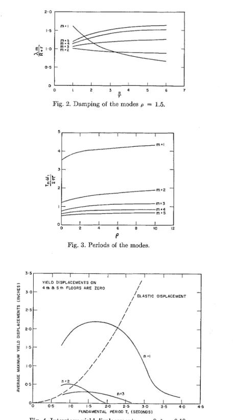
Fig. 2. Damping of the modes p = 1.5.
0 I I I I I
J
0 2 4 6 B 10 12
P
Fig. 3. Periods of the modes.
-
I YIELD DISPLACEMENTS ON / I4 I h 8 5 th FLOORS ARE ZERO /'
FUNDAMENTAL PERIOD T, (SECONDS1
YIELD DISPLACEMENTS I N MULTISTORY ASEISMIC DESIGN 445
As has already been mentioned, the large number of parameters and the many possible combinations of them ixcessitate the consideration of some special cases. I n general the relationship between the stiffness Ic, and the strength or yield value G, will be a complicated one depending on the nature of the structure. The assumption made here is that the variation of G, up the height of the building will be propor- tional to that of the stiffness. This will be true for pin-jointed structures having the same geometrical configuration of cross-ties up the height. I n order to determine the effect of changing the stiffness up the structure it is necessary to assume some type of variation. The simplest possible variation is a linear one and this has been taken here. I n particular, if
Zn
is the position of the point midway betmeell the n-th and (n-
1)-th floors, measured from the top of the structure, and h is the total height, thenlcn 4 1
+
pzn/J1) (7)The parameter p determines the stiffness and strength variation with height. This
investigation is concerned with finding, if possible, a suitable value of p.
Very little is known about the damping of structures. The few measurements made on actual structures suggest that the damping ratios of the various modes of vibra- tion are approximately equal and vary between 0.05 and 0.20.
Viscous damping is the easiest type to simulate. If only viscous damping between the floors were considered, it would be found that the damping of the modes is pro- portional to the frequency of these modes. The higher modes ~vould thus be much more heavily damped than the fundamental. If viscous damping relative to the base only were considered, the damping of the modes would decrease with frequency. A
combinatioil of the two forms allo~vs equal damping ratios of the modes to be ap- prosimately realized.
T , = the period of the nz-th mode of vibration,
A,
= the damping ratio of the m-th mode,x,,
= the maximum deflection of the n-th floor when vibrating in the m-th mode,B U L L E T I N O F T H E SEISMOLOGICAL S O C I E T Y O F AMERICA
E L A S T I C OISPLACEMENT /
0 0 . 5 1.0 1 . 5 2 . 0 2 - 5 3 . 0 3 . 5 4 . 0 4 . 5 FUNDAMENTAL PERIOD T, ( S E C O N D S )
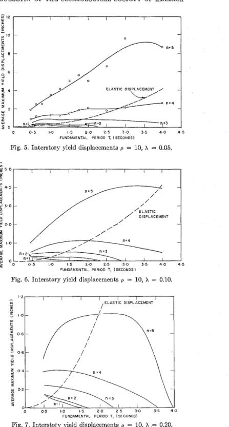
Fig. 5. Interstory yield displacements p = 10, X = 0.05.
Fig. 6. Interstory yield displacements p = 10, X = 0.10.
FUNDAMENTAL PERIOD T, ISECONOS)
YIELD DISPLACEhfENTS I N MULTISTORY ASEISMIC DESIGN 447 For any particular configuration of stiffness k,, and hence w, in the structure, t h e periods of the various modes and their shapes were found experimentally by exciting the system with an oscillator a t the mode resonances. Figure 2 shows equation (9) plotted as a function of the ratio R/r for one particular configuration of stiffness denoted by p = 1.5. It is noticed that if R / r is chosen to be 2.5, say, then the damp- ing ratio of the first three modes is approximately the same, although the fourth and fifth are higher. As the lower harmonics are the only ones that redly matter, this situation was regarded as satisfactory. For each arrangement of stiffness- variation considered, a set of curves similar to figure 2 was coilstructed and a suit- able ratio R/r decided on. Equation (9) then determines R to give any required mode damping ratio A,,,.
RESULTS
Thc family of structures considered has various fundameiltal periods, mode damp- ing ratios, and values of the parameter p. The parameter p determines a particular stiffness configuration and fixes the ratios between the periods of the harmonics. Figure 3 shows the ratio of period of the m-th mode to the period of the bottom story, itself, as a function of p. All members of the family have beell given the same
base yield value of GI = 0.5. Thc factor GI is with reference t o the mass of the bottom floor only. This means that, with respect t o the total mass of the structure, all the members have the same base yield acceleration of 0.1 g. This is a value commonly used in aseismic design. Actually, because safety factors are always in- troduced, it will mean that this set of structures would have been designed a t the base to 0.05 to 0.07 g, but, because of the implicit safety factors, yicld a t 0.1 g.
The yield values at other points in the structure are then determined by equation (8). The maximum yield displacemeilt between stories has been measured. This is defined as the maximum relative displacement measured from the initial zero posi- tion minus the elastic part of the displacement. Since each burst of noise gives a different result in a statistical fashion, the average of the maximum yield displace- ments taken over tcn runs is shown. I11 the case p = 3.0 the average of txventy runs was taken.
Figure 4 shows a completely uniform structure, p = 0. The average maximum yield displacements are plottcd against the fundamental period of the building T I .
The elastic part of the displacement, which has the same value a t each floor, is also shown. Addition of the elastic and plastic parts gives the total maximum relative displacement between floors. Naturally, in this case, most of the yielding takes place a t the base and the actual values of the base yield are large.
A building designed so that the stiffness and strength taper off quickly toward the top is given by p = 10 and is shown in figures 5 , 6 , and 7 for three different damping ratios.
A whipping effect occurs, causing the major yield to be a t the top, and again the values are large. Figure 5 shows the actual points obtained from an average of ten bursts of noise. The smooth curves only are drawn for the other cases.
It is required to find a design between these extremes which will minimize and distribute the yield displacements more evenly.
I t may be shown, both analytically and by simulation on a computer, that in a structure subject to the same assumptions made here, except that it is linearly
B U L L E T I N O F THE SEISMOLOGICAL SOCIETY O F AMERICA
1 8 I
I I I I I I
, E L A S T I C D I S P L A C E M E N T
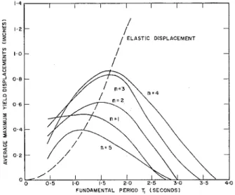
Fig. 8. Interstory yield displacements p = 1.5, X = 0.05.
FUNDAMENTAL PERIOD T, ( S E C O N D S 1
Fig. 9. Interstory yield displacements p = 1.5, X = 0.10.
elastic, equal strain up the structure is obtained approximately when p has values
between 1.5 and 3.0. This result is largely independent of period, damping, and the number of stories. Furthermore, the value of p is not critical. Unfortunately, the
elastoplastic case is much more complicated. Not only is a simple linear variation inadequate, but the required vaiiation will be a function of period, damping, and
YIELD DISPLACEMENTS IN MULTISTORY ASEISMIC DESIGN
[ E L A S T I C DISPLACEMENT 5 th FLOOR I S ZERO
2 FUNDAMENTAL PERIOD TI (SECONDS1
Fig. 10. I n t e r s t o r y y i e l d d i s p l a c e m e n t s p = 1.5, X = 0.20.
FUNDAMENTAL PERIOD TI (SECONDS)
Fig. 11. I n t e r s t o r y y i e l d d i s p l a c e m e n t s p = 3.0, X = 0.05.
2.0 I I I I I I I I I
base yield value. Yield dieplacements for several different values of p were measured. These results showed that the displacements in the elastoplastic case depend more critically on the stiffness variation up the structure than in the elastic case. This is not surprising. li'igurcs 8,9, and 10 show the case p = 1.5. The difference in the yield displacements is large.
Most buildings will have fundamental periods less than 1.5 sec. In this period range and with the simplc variation assumed i t was found that the best general
1.8
1 ELASTIC DISPLACEMENT
BULLETIN O F T H E SEISMOLOGICAL SOCIETY O F AMERICA / 1 / ELASTIC DISPLACEMENT 1
/
FUNDAMENTAL PERIOD TI (SECONDS)
Fig. 12. Interstory yield displacements p = 3.0, X = 0.10.
Fig. 13. Interstory yield displacements p = 3.0, X = 0.20.
FUNDAMENTAL PERIOD T, (SECONDS)
YIELD DISPLACEMENTS IN MULTISTORY ASEISMIC DESIGN 451 value for the elastoplastic case is given by p = 3.0. Figures 11, 12, and 13 show this situation. Depending on the damping and fundamental period, certain floors are under- or overdesigned. When A = 0.20 the design is very reasonable except for the top floor, which is ovcrdesigned. When A = 0.05 and 0.10, the third and fourth floors are underdesigned.
The seismic design of an elastoplastic structure will depend on the amount of relative displacement that may be permitted between floors as well as the amount of plastic deformation the materials may safely endure. The former is limited by the amount of distortion that the structure's cladding can stand without damage and
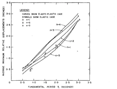
LEGEND:
CURVES SHOW ELASTO-PLASTIC CASE SYMBOLS SHOW ELASTIC CASE
0 " = I A
A n = 2 X n = 3
FUNDAMENTAL PERIOD T, (SECONOSI
Fig. 15. Comparison of elastic and elastoplastic cases p = 3.0, X = 0.10.
will be largely constant up thc height of the structure. The latter is a rather difficult problem in the fatigue of matcrials. It will depend on thc ratio of the plastic to t h e elastic strain. This ratio for p = 3.0 and A = 0.10 is shorn in figure 14. The longer the period the better, but this is limited by the permissible relative displacements. Figure 15 compares the average maximum total relative displacement in t h e elastoplastic and elastic cases for p = 3.0 and A = 0.10. The elastic case was simu- lated on the computer by removing the bias on the integrators. I n order t o avoid confusion on the graph the first three floors of the elastic casc are shown. The intcr- esting point is that here the total relative displacements are closely the same in t h e two cascs. Housner%seumed this in some work on the limit design of structures. A probability curve of the maximum total relative displacements mas constructed from two hundred runs and is shown in figure 16.
G. W . Housner, "Limit Design o f Structures to Resist Earthquakes," Proceedings, First World Conference on Earthquake Engineering, San Francisco, June, 1956.
YIELD DISPLACEMENTS I N MULTISTORY ASEISMIC D E S I G N 453
It appears that structures designed in accordance with existing codes must undergo plastic deformation during severe earthquakes. It should be the object of aseismic design to minimize and distribute these yield displacemeilts over the entire struc- ture. The achievement of an optimum design, however, is found t o be very compli- cated. The relative displacements depend more critically on the stiffness and strcngth configuration than ill the completely linear case. Thus, any particular design may be comparatively weak a t some point in its height although adequate elsc\vhere.
Any particular proposed design could be analyzed in this fashion in order to de- termine weak points, but generalized conclusions are difficult. For the much simpli- fied family of structures considered here a lincar variation denoted by p = 3.0 roughly approximates a suitable design. The probability curves are very similar for thc different stories and show only a small probability that the maximum total relative displacement is greater than twice the mean.
Bending, bending combined with shear, and rotation of the base of the structure could also be simulated on a n analog computer. I t is suggested that this type of analysis could be used to investigate many other aspects of aseismic design.
A l i s t o f a l l p u b l i c a t i o n s o f t h e D i v i s i o n o f R u i l d i n g R e s e a r c h i s a v a i l a b l e a n d may be o b t a i n e d from t h e P u b l i c a t i o n s S e c t i o n , D i v i s i o n o f B u i l d i n g R e s e a r c h , N a t i o n a l R e s e a r c h Counc il, O t t a v : ~ , Canada.