HAL Id: insu-02270104
https://hal-insu.archives-ouvertes.fr/insu-02270104
Submitted on 23 Aug 2019HAL is a multi-disciplinary open access
archive for the deposit and dissemination of sci-entific research documents, whether they are pub-lished or not. The documents may come from teaching and research institutions in France or abroad, or from public or private research centers.
L’archive ouverte pluridisciplinaire HAL, est destinée au dépôt et à la diffusion de documents scientifiques de niveau recherche, publiés ou non, émanant des établissements d’enseignement et de recherche français ou étrangers, des laboratoires publics ou privés.
Software Factory Testing Tools: an Analysis Framework
Emmanuel Ledinot, Michel Nakhlé, Philippe Robin
To cite this version:
Emmanuel Ledinot, Michel Nakhlé, Philippe Robin. Software Factory Testing Tools: an Analysis Framework. Embedded Real Time Software and Systems (ERTS2008), Jan 2008, toulouse, France. �insu-02270104�
Software Factory Testing Tools: an Analysis Framework
Emmanuel LEDINOT
1, Michel NAKHLE
2, Philippe ROBIN
31: Dassault Aviation, 78 Quai Marcel Dassault. 92552 Saint Cloud Cedex
2: CS SI. Utilities & Industry Division Technical Manager. 22, avenue Galilée. 92350 Le Plessis Robinson 3: TRIALOG, 25 Rue du Général Foy. 75008 Paris
Abstract:
Keywords: Software verification and validation, test generation, test execution, static analysis, constraint solving, tool comparison.
1. Introduction
This paper compares seven tools devoted to software verification and validation that are being developed by several participants of MoDriVal project1.
These tools are classified according to different criteria: the kind of data they process, the services they provide, their underpinning technology and foundations, and the stages of system or software testing process they are relevant to.
These tools are:
• Four test generators developed respectively by CEA, Esterel Technologies and University of Orsay. Two of them apply to data-flow programs (MTC Solver, sALLUSTe). The third one is dedicated to state-transition systems (AGATHA), and the fourth one to binary code (OSMOSE). • A test execution engine (TTS), which is
developed by Trialog.
• Two static analyzers : FLUCTUAT developed by CEA to estimate rounding errors, and Penjili developed by EADS-IW to detect string buffer overflows.
Section 2 presents the classification framework for testing tools that will be used as a reference to position the tools with respect to the testing activities.
Section 3 is a description of the tools from a technological viewpoint, i.e. by focusing on their inner parts and foundations.
Section 4 provides additional background on test case definition and coverage criteria that Section 5 refers to.
1
MoDriVal is a subproject of "Usine Logicielle" (Software Factory) project carried out within the French System@tic Cluster, funded by DGE, CG78, CG91, CG92 and CRIF.
Section 5 is the core part of the paper, presenting the mapping of the tools on four classification diagrams based on criteria discussed in sections 2 and 4.
Section 6 summarises lessons learnt from case studies carried out with the tools by CS, Dassault Aviation, EDF, Hispano Suiza, MBDA and Thales in the course of the MoDriVal project.
Then we conclude on the trends for testing tools in the commercial marketplace and the opportunity for the MoDriVal tools presented in this paper to go the market.
2. Classification framework
The state of the art related to model-based testing tools emphasizes two categories of testing approach:
• Functional testing or “black box”
• Structural testing or “white box”.
The tools can further be gathered into three families: • Tools dealing with asynchronous systems, • Tools dealing with synchronous systems,
• Tools dedicated to data handling.
Eventually testing can be deterministic or statistical and may use different techniques:
• Systems of labelled transitions (TGV, STG…)
• Constraints solving (BZ-TT/Leirios, AGATHA, GATeL…)
• Finite states machines (AsmL Tool Test, SpecExplorer…).
The specialized site http://www.stickminds.com/ references more than 268 testing tools. These tools have been investigated [1] and have been classified [2] into test design tools, graphical user interface test tools, performance testing tools, test management tools, test implementation tools, test evaluation tools and static analysis tools (see Figure 1 below).
FIGURE 1:CLASSIFICATION OF TESTING TOOLS
Here is a short description of the main categories: • Analysis: tools that analyse programs
without running them; metrics tools fall in this category.
• Design: tools which help you decide which tests need to be executed. This category also includes test data and test case generators.
• Evaluation: tools which help you evaluate the quality of your tests; including code coverage tools.
• GUI: tools which automate test execution for products with graphical user interfaces. This category includes client/server test automation tools and load testers.
• Implementation: miscellaneous tools that help you implement tests. For example, tools that automatically generate stub routines, as well as tools that attempt to make failures more obvious (such as assertion generators…).
• Load and Performance: tools that specialize in putting a heavy load on systems (especially client-server systems). These tools are often also GUI test drivers.
• Test Management: tools that automate the execution of tests for products without any graphical user interfaces. These tools help you work with large test suites.
It is worth underlying that the limits between the categories are out of focus, because many tools, can belong to several categories.
3. MoDriVal testing tools and technologies Let us start with the four test generators. In spite of apparently strong differences, they rely on the same basic idea and use the same core technology.
3.1 Test generation of binary code
The testing of legacy binary code may be unavoidable in some circumstances related to certification or management of hardware obsolescence when there is no possibility to develop a new software on the new hardware unit (the old hardware unit is then virtualized on the new one). Specified by EDF and developed by CEA, OSMOSE is designed to handle the binary code of any microprocessor provided that the processor instruction set can be translated into OSMOSE generic instruction set.
OSMOSE provides standard reverse engineering functions on binary code (control and data flow analysis, call graph display,…) and generates binary test sets driven by structural coverage criteria. Presently, there is only one predefined coverage criterion (all instruction coverage), but the criteria will be user-definable via an appropriate GUI in the future. The test cases generated can be executed symbolically by OSMOSE to "test the generated tests".
3.2 Test generation for symbolic transition systems
AGATHA, developed by CEA, is dedicated to modelling and analysis of networks of communicating transition systems. Reachability analysis of the global state space is performed symbolically, i.e. without a complete instantiation of state or action variables. By using predicates over free state variables, AGATHA symbolic states may represent infinite sets of actual states.
AGATHA is used to model automata-oriented specifications or requirements, possibly translated from formal UML activity or sequence diagrams. Verification of safety properties and generation of test cases are the two main capabilities of the tool.
3.3 Enhancement of model-level test coverage
Model Test Coverage (MTC) is currently available as a module of Esterel Technologies SCADE Suite. While submitting a model to user-defined tests, MTC is able to log the nodes and the node parts activated by the test scenarios.
MTC Solver is a prototype add-on to MTC which is developed by CEA and Esterel Technologies. It aims at facilitating the way to obtain a 100% model-level structural coverage. Given a current coverage ratio, MTC Solver generates additional tests to activate the remaining non-activated parts that are suspected to be possible "dead" nodes.
It is also possible to define “observers”, in a manner similar to what is done for model-checking of safety
properties, and to ask the tool to generate test cases that both increase the model coverage and satisfy the observers.
3.4 Statistic test generation of data-flow programs
sALLUSTe is a test generator for data-flow programs developed by CEA and Orsay University/LRI.
sALLUSTe handles also structural coverage criteria, but oppositely to MTC solver, it explores randomly the structure of a data-flow model (i.e. a SCADE model in practice). At present the probability distribution mapped on the nodes of the model network of equations is uniform, but in future versions of the tool it is planned that "weights" (testing effort objectives) on structural points of a model (nodes, equations etc.) might be user-defined in order to adjust, i.e. to bias, the statistical coverage.
The four test generators presented here process three different kinds of objects:
• Control flow graphs labelled by binary instructions,
• Parallel compositions of symbolic state-transition systems,
• Networks of conditioned equations,
Three of them are deterministic test generators while the last one is stochastic.
However, in spite of significant differences, the tools are based on similar principles and they use similar ways to compute the tests they generate. They proceed as follows :
1. First an execution path is computed on a structure that depends on the structural criterion selected (graph-based coverage, loop unfolding bounds, etc.) and the Boolean conditions met along this path are collected. In AGATHA, MTC Solver and sALLUSTe the "paths" are traces or multi-cycle sequences of synchronous steps. An user-bounded and user-focused unfolding of cycles (SCADE) or interleaved transitions (AGATHA) is performed. In OSMOSE, a path is a branch of the control flow tree.
2. Second the set of Boolean conditions (predicates over free variables that are the path local reachability conditions) is submitted to a constraint solver that tests if this set of constraints might be satisfied. When the constraints are satisfied, the constraint solver produces a set of solution intervals for the constrained variables. Any value chosen in these intervals ensures the accessibility of the path.
3. Eventually every input variable of the model (AGATHA, MTC Solver, sALLUSTe) or the binary program (OSMOSE) is given an
actual value which is randomly chosen in the solution intervals.
Constraint solving is the key technology used in step 2 above [3], [4]. GATeL, which includes the Eclipse constraint solver, or Eclipse per se, is the common core component used by the four test generation tools presented in this paper.
3.5 TTCN-3 test generation and execution
TTS is a test execution engine that performs tests on programs hosted in a workstation or in embedded devices. TTS complies with a standard test methodology used by the telecom domain (ISO 9646, TTCN) and uses a black-box testing approach. The latest version of the standard known as TTCN-3 shall be used by the automotive industry in the future to specify the conformance tests of basic software components.
Within the MoDriVal project, a new version of TTS compliant to TTCN-3 was developed and integrated with AGATHA test generator described above in order to provide and experiment a model-to-test workflow covering test generation and test execution.
The last two tools (FLUCTUAT and Penjili) considered in this paper are static analysers. These tools provide exhaustiveness of analysis (proofs) to the expense of over-approximation (false negatives) and computational complexity (analysis time and space footprint). Thus they can be considered as verification tools. It is interesting to note that constraint solving (in case of sound and complete constraint solvers) also provides exhaustiveness in satisfiability analysis. There the test generators based on constraint solving such as those described above may be considered as reachability verification tools as well.
3.6 Static analysis of rounding errors
FLUCTUAT developed by CEA propagates through ANSI C source code error terms which (over)-approximate the rounding errors made by floating point computation. Floating point computation is supposed to conform to IEEE 754 specification. The C source codes may be annotated at some critical control points to provide application-specific information on the value range of given key variables. Because of decidability and computational complexity issues, the accuracy .vs. efficiency trade-off is currently such that FLUCTUAT may fail to infer precise enough bounds or intervals. Annotations are taken into account by FLUCTUAT and are instrumental in controlling over-approximations. A graphical user interface displays interval or error bars on the source code.
3.7 Static analysis of string buffer overflows
Penjili is a static analyser whose development started at EADS Innovation Work within MoDriVal project. It is dedicated to the detection of potential security attacks through string buffer overflows. Penjili processes ANSI C source code files of programs that make extensive calls to string handling libraries. The tool relies on the definition of an abstract domain specially designed for the purpose of tracking efficiently dangerous memory read/write operations in character array manipulation.
4. Mapping testing tools w.r.t. testing process
4.1 Testing Processes
In software engineering processes, inspection and testing activities can be organized in stages according to the V-model (see Figure 2).
Figure 2: V-Model of software testing
The V-model integrates together testing and design activities by showing, how the testing activities on the right-hand side verify the outcome of design activities on the left-hand side. A test plan corresponds to each stage of the software construction. Requirement analysis is the stage where the software engineer thinks about the information obtained during the initial stage of requirement elicitation. Requirement specification documents and design documents are inspected carefully before the coding stage begins. Checklists are the basic tools used for the inspection of requirements. Requirements give guidelines for the subsequent construction stages as well as the criteria to be used for the software acceptance. The acceptance test plan is produced at the requirement elicitation stage. The acceptance test plan helps users testing the system and checking with acceptance criteria whether their requirements are fulfilled.
Then the design stage of the software architecture can be divided into the following activities:
• Functionality-based architecture design, which decomposes the architecture into
needed components and the relationships between them,
• Evaluation of quality attributes of the architecture,
• Transformation of the software architecture in order to improve its quality, and
• Component design.
Component design means that the structure of each individual component is designed. The components have to collaborate with each other and cannot be considered as standalone items. The dependencies between components must be designed too. Components are often designed in an object-oriented way in terms of classes and their relationships. The functional logic is split between interfaces and dependency implementation. The execution environment of the components and the test plan for the components needs to be defined too. The whole testing process depends on who performs the tests, i.e. a component provider, an integrator or a component customer. A provider needs black and white box testing techniques. An integrator needs only black box testing techniques to perform interface testing, A customer uses black box techniques for acceptance testing.
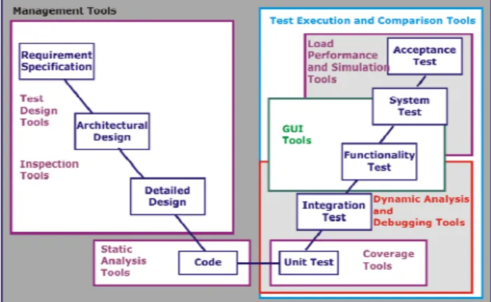
The testing process should be assisted with specialized testing tools. The categories of testing tools presented in Section 1 may be mapped onto the V-model of testing as shown below (see Figure 3).
Figure 3: Mapping of testing tool categories on the V-model of testing
4.2 Test case creation
Test cases can be created using white box or black box testing techniques. White box and black box methods can be used together in order to maximise the test coverage.
4.2.1 Black box testing techniques
Black box testing techniques are used if the source code is not available. In black box testing, test cases are derived from requirement specification, use cases or contracts. A contract defines the interfaces of the component, its dependencies with respect to
other components and the component execution environment. Contracts are normally used for testing distributed components. Black box testing is used in integration, system and acceptance testing stages. Commonly used black box testing methods are boundary value and equivalence partitioning (which can also be improved by boundary value analysis). These methods are detailed below.
Boundary value analysis: This method addresses array bound violation, detection of potential stack overflows, buffer overruns, freeing of unallocated memory… Several studies have shown that programmers make errors especially when coding loops. Boolean expressions, such as <, >, =, ≠, ≤ and ≥ are often erroneously coded and this results in the loop being traversed one time too much or one time too less. That is why it is necessary to select test cases close to the boundaries. The guidelines for the boundary value analysis are:
• If an input specifies a range of valid values, write test cases for the limits of the range and invalid input test cases for conditions just beyond the limits
• If an input specifies a number of valid values, write test cases for the minimum and maximum number of values and one beneath and beyond these values.
Equivalence partitioning: In most cases, the system cannot be exhaustively tested, so the input space must be somehow partitioned. Equivalence partitioning is a test case selection technique in which the test designer examines the entire input space defined for the system under test and looks for sets of input that are processed "identically". Identical behaviour means that test inputs belonging to one equivalence class traverse the same path of execution through the system. Equivalence partitioning is based on the following assumptions:
• If the system works correctly with one test input in an equivalence class, the system works correctly with every input in that equivalence class
• Oppositely, if a test input in an equivalence class detects an error, all other test inputs in the equivalence class will find the same error.
Equivalence classes are defined from an analysis of the requirement specification document. It is important to note that equivalence partitioning is always based on the test designer's intuition and thus may be imperfect. The guidelines for the equivalence partitioning analysis are:
• If the input specifies a range of values, one valid (within the range) and two invalid (one outside each end of the range) equivalence classes are defined
• If the input specifies a specific value within a range, one valid and two invalid equivalence classes are defined
• If the input specifies a set of valid values, one valid (within the set) and one invalid (outside the set) equivalence class are defined
• If there is reason to believe that the system handles each valid input value differently, then define one valid equivalence class per valid input
• If there is reason to believe that elements in an equivalence class are not handled identically, subdivide the equivalence class into smaller equivalence classes
• One or several equivalence classes are always defined for the illegal values. Illegal value is incompatible with the type of the input parameter.
This may lead to an explosion in the number of equivalence classes.
4.2.2 White box testing techniques
If the source code is available, white box testing techniques can be used. White box techniques ensure that the internal logic of the system is adequately tested. In white box testing, test cases are derived through a careful examination of the source code of the component. White box testing can find errors that are deeply hidden in the source code details. White box testing is used at the component testing stage (see Figure 2). When testing the component at source code level, both the control-flow and the data-flow of the component can be tested.
Control-flow testing: Control-flow testing means that different paths according to the control-flow of the component are followed. A standard representation for the control-flow of a component is a flow graph, which abstracts the execution of the component into a graph-like structure. The nodes of a flow graph stand for the statements of the component and the edges stand for the control transfer between the statements. Statements where the control diverges such as conditional statements or loops are the most important items from the control-flow testing point of view. The adequacy of control-flow testing is measured in terms of coverage. The coverage indicates how extensively the system is executed with a given set of test cases. The basic types of coverage are:
• Statement coverage, where each statement is executed at least once. This is the weakest criterion and does not normally ensure a faultless code. 100% statement coverage is usually too expensive and hard
to achieve, especially if the source code includes "dead code".
• Path coverage, where every possible execution path is traversed. Exhaustive path coverage is generally impractical and impossible because loops increase the amount of execution paths
• Branch coverage, where each statement is executed at least once and each decision in the program takes all possible outcomes at least once. Branch coverage criterion is stronger than statement coverage because if all the edges in a flow graph are traversed, then all the nodes are traversed as well. Branch coverage is also known as decision coverage.
• Condition coverage, where each statement is executed at least once and every condition in a decision in the program takes all possible outcomes at least once. Complete condition coverage does not necessarily imply complete branch coverage so they do not compensate each other
• Multiple condition coverage, where each statement is executed at least once and all possible combinations of condition outcomes in each decision occur at least once. This is the strongest criterion that requires to test the component with more test cases and in a more detail manner than the other criteria. Composite types of coverage may also be introduced such as Modified Condition Decision Coverage (MC/DC) which is recommended as a complement to functional tests by the DO-178B standard used in the aircraft industry. The idea behind MC/DC is as follows. For each condition occurring in a program, a test suite is required that ensures that for each atom in the condition there exist two test cases that yield different results when independently toggling the atom under consideration. Such test suites may not always exist. If a MC/DC test suite exists, then there are n + 1 test cases for each condition that consists of n literals. Data-flow testing: Data-flow testing methods explore the events related to the status of variables during the component execution. The key event related to a variable is the assignment of value to the variable.
5. Classification of MoDriVal tools
Figures 4a and 4b present a mapping of MoDriVal tools on aforementioned categories. Along the Y axis of figure 4a, we distinguish between tools dedicated to sequential code or synchronous models and tools handling asynchrony. Along the X axis, we distinguish between tools supporting functional
testing and tools supporting structural testing. The name of the tools are post-fixed with (s), (m) or (c) when the tests they generate or execute are performed respectively at system-level, model-level or code-level.
Figure 4a: First classification
TTS performs system-level functional testing of embedded devices (for instance through their network and protocol interfaces). It can be used also to perform code-level functional testing of a software component on a workstation.
AGATHA operates only at model level, on symbolic transition systems communicating asynchronously through message queues.
The other tools presented deal with sequential code (FLUCTUAT, Penjili, OSMOSE) or synchronous concurrent models of sequential code (sALLUSTe, MTC Solver).
Regarding the structural .vs. functional partitioning, let us add a few comments:
• MTC solver is positioned “across the vertical frontier” on the figure above because depending on whether observers are used or not, the tests generated are purely structural or not. When used in a DO178 context for instance, the tests generated to improve model coverage have to be back traceable to some software requirements. In order to do so, these requirements have to be formalized as observers linked to the tested model so that they enforce constraints (i.e. "functional meaning") on the generated I/O sequences.
• The discussion on MTC Solver is also relevant for sALLUSTe.
• AGATHA lies also across the vertical frontier because the tests generated using reachability conditions may be structural or functional, depending on the "flavour" of the reachability predicate.
• FLUCTUAT might have also been positioned near the vertical frontier because some functional properties may be demonstrated by proving (through abstract interpretation) that the range of some variables are within given bounds. For example, equality between two floating-point expressions exp1 and exp2 may be proved by showing that variable epsilon is bounded to [-10-6 , +10-6 ] where epsilon is assigned in the code to (exp1 - exp2). However, numerical precision is most of the time handled as a non-functional property. Moreover, current over-approximation issues on loops and conditionals may make functional properties hard to prove with FLUCTUAT. This is why it is eventually positioned on the structural side.
The second classification map below (Figure 4b) is self-explanatory. Most of the tools developed and evaluated in the project are deterministic white box testing tools.
Figure 4b: Second classification
We now discuss the figure 5a below that presents the positioning of the tools with respect to the system and software development stages of the V-model of testing.
AGATHA is positioned at the system or software requirement capture stage. Using UML class and activity diagrams to formalize the captured requirements, or possibly to perform software analysis, AGATHA can import the UML models and generate requirement test cases from these models.
Figure 5a: Mapping of MoDriVal tools on the V-model of testing
Then we positioned MTC Solver along both branches of the V-process. In principle, Model Test Coverage does not apply to implementation and code verification. However when the software code is generated by the qualified version of SCADE (known as KCG), certification credits may be obtained so that the unitary tests performed at model-level need not be replayed at code-level. Thus MTC Solver may also apply (indirectly) to code testing since model coverage may supersede generated-code coverage in these particular circumstances.
sALLUSTe was positioned on the left-hand side of the process for the sake of clarity. However since MTC Solver and sALLUSTe rely on the same constraint solver and may process the same SCADE models, sALLUSTe might be added on the right-hand side as well.
FLUCTUAT, OSMOSE and Penjili are dedicated to software verification at the coding stage and are positioned accordingly in figure 5a.
The experiments made with the current version of FLUCTUAT by Dassault Aviation, Hispano Suiza and MBDA showed that the C code programs need very often to be modified to get the best out of the analyzer. Such modifications are unacceptable by DO-178 compliant software verification process and this the reason why for the time being we consider FLUCTUAT as a tool to be used only when it is still possible to choose how to write the code. When FLUCTUAT maturity level increases, this tool will become suitable for unit and integration testing stages as well.
OSMOSE and Penjili are also regarded as tools supporting the coding stage since none of them execute tests.
OSMOSE provides facilities to "check" the binary tests it generates, in the sense that these tests are evaluated through symbolic interpretation of the binary code, as if it was executed by the intended hardware.
However, whether static analyzers such as FLUCTUAT, OSMOSE and Penjili may supersede part of the testing activities in the future or not is currently a matter of debate in the working groups preparing revision C of DO-178.
As TTS is devoted to system-level integration and acceptance tests, it is positioned accordingly on the upper right part of the verification branch.
6. Overview of MoDriVal tool experimentations Let us give a quick overview of the MoDriVal project case studies that put the tools at work. Case studies were relevant to avionics software, critical control software for nuclear power plants and automotive embedded software.
AGATHA was experimented in two different ways by EDF and Thales Research & Technologies.
EDF aimed at analyzing system requirements through UML modeling and test case generation while Thales R&T attempted to set up a process where software design tests were derived in a semi-automatic way from AGATHA-generated requirement tests.
OSMOSE was evaluated by EDF and Hispano-Suiza. EDF expects OSMOSE to help facing hardware obsolescence and binary porting issues while Hispano-Suiza is concerned with DO-178 mandatory tests of optimized binary codes when source traceability is broken by compiler optimization.
Dassault Aviation, Hispano Suiza and MBDA used FLUCTUAT on many different mathematical algorithms to assess the functional impact of rounding errors, to prove stability, robustness or convergence properties. Understanding the foundational background of the tool and defining a methodology to tune the numerous parameters of the abstract interpreter were unanimously recognized as critical issues.
CS experienced sALLUSTe on automotive embedded software. Dassault Aviation, Hispano Suiza and MBDA are currently assessing sALLUSTe on avionics SCADE models.
7. Commercial tool landscape
The landscape of commercial test environments has experienced some significant changes recently. There is a major trend towards integrated environment that span over the various categories of test activities presented in Figure 1 at the beginning of the paper. These environment provide numerous tools that allow designers to perform a whole-program inter-procedural analysis on C/C++/Java
code and to identify complex programming bugs that can result in system crashes, memory corruption, and other serious problems. As examples of such integrated test environment, we have selected the following tools:
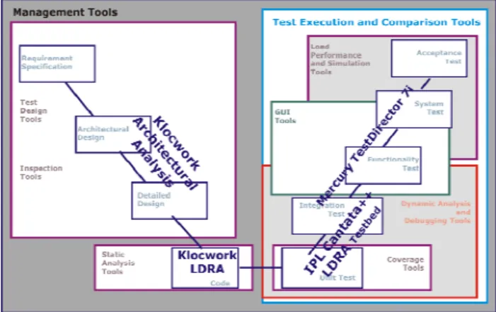
• Klocwork, a set of leading static analysis tools to “cure” defects and security vulnerabilities in C/C++/Java code. Klocwork includes Metrics and Trending, Project Central, Architectural Analysis, Integration with Eclipse IDE…
• Cantata++ which performs code coverage plus unit and integration testing at a reasonable cost
• LDRA, a range of cutting edge, sophisticated software analysis tools such as static analysis and code coverage tools for C, C++, C#, Ada83/Ada95 and assembler. Static analysis features include code visualisation, programming standards checking and complexity metrics. Code coverage is available for different coverage levels including MC/DC level A for the D0-178B standard.
• Mercury’s TestDirector 7i which incorporates all aspects of the testing: requirements management, planning, scheduling, running tests, defect tracking... into a single browser-based application.
The Figure 5b below presents how these commercial tools are positioned on the V-model of testing.
Figure 5b: Mapping of commercial tools on the V-model of testing
The well-known software editor The Mathworks follows also the trend towards tool integration by providing static analysis capabilities (based on Polyspace) for the software code generated from the Matlab/Simulink models. Several test management environments are now available : OptimalTest, TSSI, TAU Tester, TT-Workbench, OpenTTCN Tester (the last three ones being specialized for TTCN-3 test language). Compiler / debugger vendors provide also integrated test environment that include
run-time error analysis, stack analysis, code coverage analysis and of course in-circuit debugging or emulation (Greenhills, iSystem, Lauterbach, etc.).
8. Conclusion
How could the MoDriVal tools fit in the landscape of commercial tools ? This is both a question of functionality and technical maturity.
TTS is a tool whose maturity is currently high enough to allow Trialog to integrate it into industrial testbenches. The TTCN-3 version of TTS developed during the MoDriVal project provide functionalities similar to OpenTTCN and TT-Workbench tools. A way for TTS/TTCN-3 to reach the market would be to integrate it as a plug-in to existing integrated test environment in order to support the future conformance testing of AUTOSAR software components. Since TTS/TTCN-3 was developed as an Eclipse plug-in, the integration would be facilitated for Eclipse-based environment.
All other MoDriVal tools presented in this paper are still research prototypes. The integration of these tools as plug-in to Eclipse-based environment is also a possible way to the market. These tools however still need to maturate.
Penjili and FLUCTUAT may be compared to equivalent static analysis tools provided by Klockwork and LDRA environment. No commercial tools mentioned above match the capabilities of MTC Solver and sALLUSTe yet. Similarly commercial products providing binary code reverse engineering capabilities exist, but to our best knowledge coverage-driven test case generation at binary code level is a distinctive feature of OSMOSE.
9. References
[1] M. Nakhlé: "Document de Travail CS, Projet Usine Logicielle/SP MoDrival, Tâche 2.1/MOD-CS-1 (Le besoin, l’état de l’art en compression / décompression de vecteurs de tests, tests et réduction de modèles)". 25 juin 2007, pp. 35-83. [2] S. Xanthakis, P. Régnier, C. Karapoulios: “Le test
des logiciels”. Hermès – Lavoisier, Novembre 1999. [3] S. -D. Gouraud, A. Denise, B. Marre: "A new way of automating statistical testing methods", Sixteenth IEEE Int. Conf. on Automated Software Engineering (ASE 2001), Coronado Island, Californie, pages 5--12. IEEE Computer Society Press, novembre 2001.
[4] B. Marre and A. Arnould: "Test sequences generation from lustre descriptions: Gatel", Fifteenth IEEE Int. Conf. on Automated Software Engineering (ASE 2000), Grenoble , pages 229--237. IEEE Computer Society Press, septembre 2000.
[5] Céline Bigot, Alain Faivre, Jean-Pierre Gallois, Arnault Lapitre, David Lugato, Jean-Yves Pierron, Nicolas Rapin: "Automatic Test Generation with AGATHA". TACAS 2003: 591-596
10. Main Links
10.1 MoDriVal
• Usine Logicielle: http://www.usine-logicielle.org/ • AGATHA, FLUCTUAT, OSMOSE:
http://www-list.cea.fr/ • MTC Solver: http://www.esterel-technologies.com/ • Penjili: http://www.eads.com/ • sALLUSTe: http://www.lri.fr/asspro/ • TTS: http://www.trialog.com/ 10.2 TTCN standard • TTCN-3 standard: http://www.ttcn-3.org/
10.3 Commercial test environments
The links in this section do not imply the endorsement of any of these tools by the authors. Neither does the order of the presentation reflect any preferences.
• Cantata++: http://www.ipl.com/ • Klocwork: http://www.klocwork.com/ • LDRA: http://www.ldra.com/ • OpenTTCN: http://www.openttcn.com/ • OptimalTest: http://www.optimaltest.com/ • Polyspace: http://www.mathworks.com/products/polyspace/ • TAU Tester: http://www.telelogic.com/
• TestDirector:
https://h10078.www1.hp.com/cda/hpms/display/m ain/hpms_home.jsp?zn=bto&cp=1_4011_100__ • TSSI: http://www.tessi.com/Products.aspx?id=19 • TTWorkbench: http://www.testingtech.de/