Dynamic Instabilities Imparted by CubeSat Propulsion
byTimothy Joseph Cordeiro
B.S. Physics
United States Air Force Academy, 2014
Submitted to the Department of Aeronautics and Astronautics in partial fulfillment of the requirements for the degree of
Master of Science in Aeronautics and Astronautics at the
MASSACHUSETTS INSTITUTE OF TECHNOLOGY
June 2016
@
Massachusetts Institute of Technology 2016. All rights reserved.A uthor ... C ertified by ... Accepted by... MASSACHUSETTS INSTITUTE OF TECHNOLOGY
JN
28
016
LIBRARIES
Signature redacted
Department of A4rinautics and AstronauticsMay 19, 2016
Signature redacted
Keri( Cahoy Assistant Professor of Aeronautics and Astronautics
Thesis Supervisor
Signature redacted
I
Paulo C. Lozano Associate Professor of Aeronautics and Astronautics Chair, Graduate Program CommitteeDynamic Instabilities Imparted by CubeSat Propulsion
by
Timothy Joseph Cordeiro
Submitted to the Department of Aeronautics and Astronautics on May 19, 2016, in partial fulfillment of the
requirements for the degree of
Master of Science in Aeronautics and Astronautics
Abstract
As the role of CubeSats evolves to include more challenging and complex missions in addition to technology demonstrations, the demand for agility have increased. As the technology improves and gains flight heritage, CubeSats are being deployed to accomplish more difficult missions including, but not limited to, large constellations and missions beyond Low Earth Orbit (LEO). To perform missions like station keeping for constellations, and to move beyond LEO, CubeSat developers are increasingly integrating propulsion into the design of their CubeSats. In addition, more complex payloads and communication systems require more power generation, which leads to larger deployed solar arrays. Meanwhile, the limiting factor for the CubeSat remains the size and weight constraints of the containerized launch deployers. In order to meet these constraints, the solar array design has to trade stiffness and strength for size. In this work, we investigate whether designs that use a combination of propulsion and solar arrays stress the dynamics of the solar panels and the hinges that hold them in place. Our approach uses SimXpert to perform dynamic simulations on CubeSat models, both 3U and 6U, with deployable solar panels and propulsion forces. By default, SimXpert treats every part as a rigid body and stress is not calculated. By doing a modal analysis of the panels in Nastran and importing the results into SimXpert, stress on the panels can be tracked during propulsive maneuvers. We determine that Margin of Safety (MoS) for the solar panels analyzed is over 100 when combined with three different COTS propulsion units. We also show the movement induced on the panels from propulsion can cause errors in body attitude ranging from 0.04 to 90 degrees. The worst case showed a difference becoming one degree in five seconds before growing exponentially to 90 degrees in 30 seconds.
Thesis Supervisor: Kerri Cahoy
Acknowledgments
First, I want to thank my family. Their constant love and support is so important
to me and to my success. I want to thank my adviser, Kerri Cahoy, for her guidance
and support during my time at MIT. I also want to thank Mike Shatz and Dennis
Burianek who supported me at MIT Lincoln Laboratory and gave me the opportunity
to work with the fantastic people in Group 75. Thank you John Kuconis for the
opportunity to be a Lincoln Laboratory Military Fellow so I that could pursue my
graduate degree at MIT. I want to thank Mike Long, Mike Mastovich, and Greg Allen
for their help with structures and thermal for MiRaTA. Finally, I want to thank all
the members of the MiRaTA team, the STAR Lab, and the Space Systems Lab.
Contents
Abstract . . . .
2
Acknowledgments . . . .
3
Contents . . . .
5
List of Figures . . . .
8
List of Tables . . . .
10
1 Introduction/ Motivation 121.1 Introduction . . . .
12
1.2 M otivation . . . . 13 1.2.1 CubeSats . . . . 13 1.2.2 Propulsion . . . . 16 1.2.3 Power Requirements . . . . 20 1.2.4 Dynamic Concerns . . . . 23 1.3 MiRaTA . . . . 25 1.4 KitCube . . . . 28 1.5 Contributions . . . . 30 1.6 Thesis Organization. . . . . 31 2 Approach 33 2.1 Chapter Overview . . . . 33 2.2 M odeling Approach . . . . 342.2.1 Recreate Peters' Model . . . . 35
2.2.2 MicroMAS-1 vs. M iRaTA . . . . 36
2.2.3 Modeling a 6U CubeSat . . . . 41
2.2.4 Rigid vs Flexible Bodies . . . . 42
2.2.5 Addition of Propulsion . . . . 44
2.2.6 Hinge geometry . . . . 46
2.3 M odel Parameters. . . . . 46
2.4 Interpreting Simulation Results . . . . 53
3 Analysis 55 3.1 Single Panel Model Dynamics . . . . 55
3.1.1 Rigidly Connected Solar Panel . . . . 56
3.1.2 Flexible Hinge . . . . 58
3.2 Solar Panels . . . . 61
3.2.2
Development of Panels . . . .
3.3 EM Solar Panel Deployment Test . . . .
3.3.1
Methodology . . . .
3.4 Validation of Model . . . .
3.4.1
Deployment Model . . . .
3.4.2
Correlating Test Data with Simulations
4 Simulations
4.1 Chapter Overview. . . . .
4.2 Deployments. . . . .
4.2.1
MiRaTA Deployment
4.2.2
KitCube Deployment
4.3 KitCube . . . .
4.3.1
Offsetting Hinge-driven
4.3.2
Green Monopropellant
4.3.3
iEPS . . . .
4.3.4
MRJ . . . .
4.3.5
6U Sensitivity Analysis
4.4 MiRaTA . . . .
4.4.1
Green Monopropellant
4.4.2
iEPS . . . .
4.4.3
MRJ . . . .
4.4.4
3U Sensitivity Analysis
5 Conclusion
5.1 Analysis of Results . . . .
5.2
Future Work . . . .
Accelerations
63
72
72
75
76
77
81
81
82
83
85
86
87
91
99
102
105
106
107
110
111
114
116
116
118
List of Figures
1-1
Number of CubeSat launches by year from 2005 to 2014 [6].
14
1-2 CubeSat Applications, Historic versus Projected [8]. These
charts show the trend that CubeSats are increasingly being
utilized for science and sensing missions.
. . . .
16
1-3 The Orbital ATK LEOStar-2 Bus used by the TESS
Space-craft [19]. . . . .. 21
1-4 MiRaTA's pitch-up maneuver and Concept of Operations [24]. 26
1-5 CubeSat Protrusions [25]. ...
27
1-6 Allowed CubeSat Protrusions. P-POD on the left, ISIPOD
on the right [26]. Note the second dimensions from the top
on both diagrams, 6.5 vs 9. That is the volume given for
protrusions from the rails. ...
27
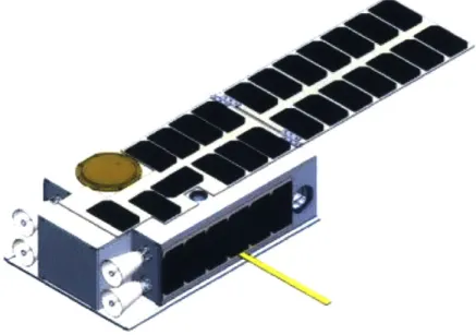
1-7 An early CAD rendering of KitCube showing the propulsion
thrusters and solar panels. The design continues to improve
in fidelity .
...
...
29
1-8 The initial CONOPS and mission phases for KitCube. ...
30
2-1 Deployment Test Set Up. .
...
40
2-2 UTJ cell from Spectrolab, Inc. [32] . . . .
44
2-3 Left: The Busek MRJ [17]. Right: MIT iEPS [33] next to a
1U chassis. ...
46
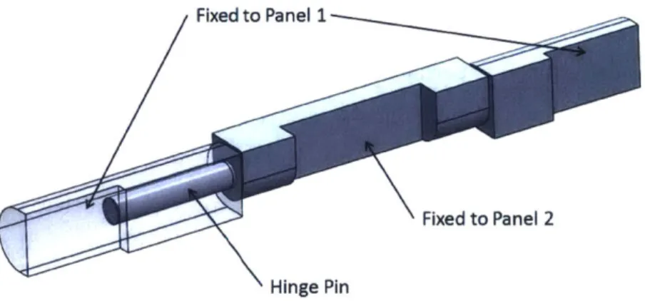
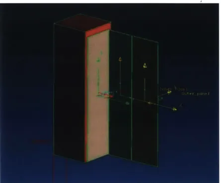
2-4 Annotated CAD model of a solar panel hinge. . . . .
50
2-5 Force profile for the Busek green monopropellant thruster [38]. 53
3-1 A graphical representation of the 1-Dimensional problem of
propulsion affecting a rigid solar panel. . . . .
56
3-2 The torques and forces due to propulsion on a 1-Dimensional
solar panel .
...
...
57
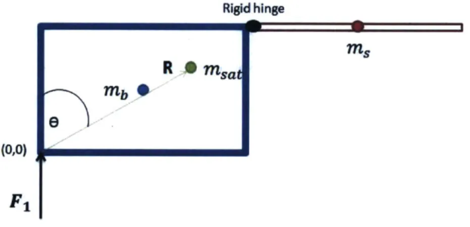
3-3 Free Body Diagram of the body of the satellite connected to
the solar panel via hinge with an applied Force. . . . .
59
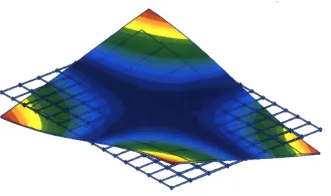
3-4 The first normal mode, 10.44 Hz, for the 2D PCB-equivalent
p anel. . . . .. 64
3-5 Image from Patran zoomed in on the 6U panel showing the
element boundaries. The lines between the cells indicate that
each cell is not connected to its neighbors. . . . .
67
3-6 The first normal mode, 117.3 Hz, for the 6U solar panel
con-strained with an ASET for SimXpert. ...
69
3-7 The first normal mode, 133.5 Hz, for the 3U solar panel fixed
on the long edge...
70
3-8 The first normal mode, 42.5 Hz, for the 3U solar panel
con-strained with an ASET.
...
.
71
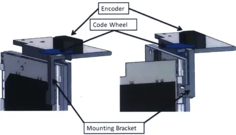
3-9 Close up of deployment test set up. Left (a) shows the stowed
configuration, and Right (b) shows the deployed configuration. 74
3-10 The SimXpert model of the EM solar panel deployment test.
77
3-11 Deployment results from SimXpert showing the effects of
changing the damping, cma,, and stiffness, k, parameters. . . 79
4-1 Deployment results for MiRaTA from SimXpert. ...
84
4-2 Deployment results for KitCube from SimXpert... ..
86
4-3 The SimXpert model of KitCube with a reference axis.
. ..
87
4-4 The pitch angle of the KitCube chassis with no propulsion. .
88
4-5 The angular acceleration causing the pitch angle. ...
88
4-6 The location of the force used to offset the acceleration caused
by the hinge forces in the SimXpert model. ...
90
4-7 The plot is used to determine the correct offsetting force
value. .
. . . .. 90
4-8 Nomenclature for the location of the propulsion units on the
-Z
face of the KitCube SimXpert model. ...
92
4-9 Comparing the pitch angle for KitCube when the top 2 thrusters
are firing for two different constraints on the solar panel.
.
.
94
4-10 The difference in pitch angle for KitCube when the top 2
thrusters are firing for two different constraints on the solar
p anel. . . . .. 95
4-11 Comparing the pitch angle for KitCube when the bottom 2
thrusters are firing for two different constraints on the solar
p an el. . . .. 96
4-12 The difference in pitch angle for KitCube when the bottom 2
thrusters are firing for two different constraints on the solar
p an el. . . .. 96
4-13 The difference in attitude angles for KitCube when the corner
2 thrusters are firing for two different constraints on the solar
panel. . . . .. .
...
. .. .. . .. . ... ... ... 98
4-14 The location of the force vectors for the iEPS thrusters. . . . 99
4-15 The pitch angle of KitCube using the top iEPS thrusters,
corrected for the leftover acceleration .
...
102
4-16 The location of the force vectors for the Micro-Resistojet
thrusters.. ...
103
4-17 The difference in pitch angle for KitCube when the bottom
MRJ thrusters are firing for two different constraints on the
solar panel.. . . . .. . . . 104
4-18 The SimXpert model of MiRaTA with a reference axis. . . . 106
4-19 The SimXpert model of MiRaTA with the green
monopro-pellant thrusters modeled as point forces (in green) . ...
108
4-20 Comparing the pitch angle for MiRaTA when the bottom
thruster is firing. ...
109
4-21 The difference in pitch angle for MiRaTA when the bottom
thruster is firing. ...
...
110
4-22 The MiRaTA SimXpert models with the iEPS thrusters
mod-eled as point forces on the -Z face (in light blue)...
..
111
4-23 The MiRaTA SimXpert models with the MRJ thrusters
mod-eled as point forces on the -Z face (in blue). ...
112
4-24 Comparing the pitch angle for MiRaTA when the bottom
thrusters are firing. ...
113
4-25 The difference in pitch angle for MiRaTA when the bottom
thrusters are firing. ...
. 113
List of Tables
1.1
Comparison of propellant options [14] with TRL 6 or greater. 17
2.1
Steps to get to final SimXpert model. ...
35
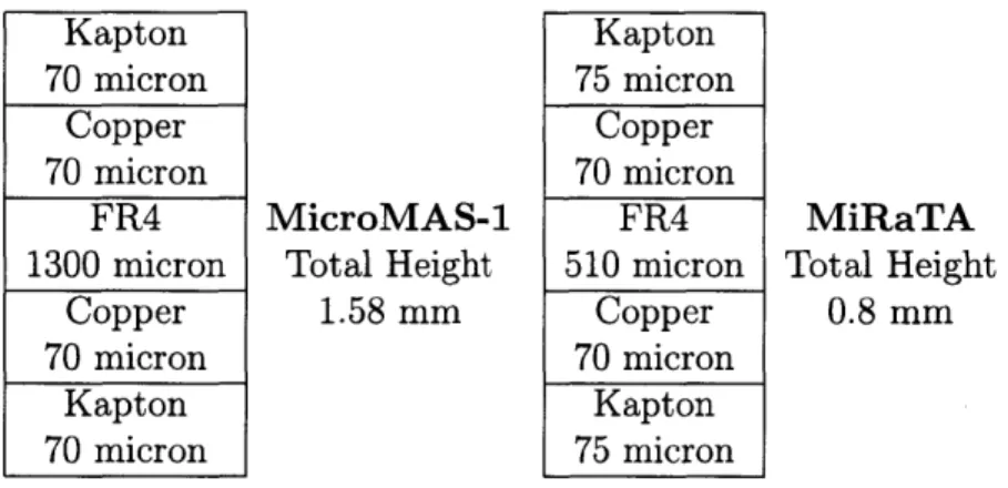
2.2 A notional comparison of thicker, single deployed and thinner,
double deployed solar panel stacks . ....
...
38
2.3 Notional solar panel stacks for double sided solar panels with
a single deployable on the left, and a double deployable panel
on the right. ...
42
2.4 Hinge values assumed for the three CubeSats. . . . .
47
2.5 Initial IMPACT Parameters. . . . .
49
2.6
Solar array material properties. ...
50
2.7 The material make up of the Solar Cells used for MiRaTA
and KitCube. ...
51
2.8
Propulsion units with their thrust and specific impulse values
[17][18][38] .
...
...
53
3.1
The natural frequency of the KitCube Solar Panel calculated
with different models. ...
63
3.2
The material properties for PCB calculated with a weighted
average.. . . . .
64
3.3
The normal modes for the KitCube solar panel with different
constraints .
...
...
68
3.4 The natural frequency of the MiRaTA outer solar panel
cal-culated with different models...
.
70
3.5
The normal modes for the MiRaTA solar panels with different
constraints .
...
...
71
4.1
Final IMPACT Parameters. ...
85
4.2 Stress results for the KitCube model using the green
mono-propellant thrusters. ...
93
4.3 Stress results for the KitCube model using the iEPS thrusters.100
4.4 Stress results for the KitCube model using the Micro-Resistojet
thrusters. ...
104
4.5 Stress results for the KitCube model using increasingly more
powerful thrusters. ...
105
4.6
Stress results for the MiRaTA model using different
orienta-tion of thrusters. . . . .
107
4.7
Stress results for the MiRaTA model using the green
mono-propellant thrusters . . . 109
4.8
Stress results for the MiRaTA model using the iEPS thrusters.
111
4.9
Stress results for the MiRaTA model using the Micro-Resistojet
thrusters...
112
4.10 Stress results for the MiRaTA model using more powerful
Key Nomenclature
ADCS Attitude Determination and Control System CAD Computer-aided design
CONOPS concept of operations COTS Commerical off the shelf
CSD Planetary Systems Corporation Canisterized Satellite Dispenser CTAGS Compact TEC Atmospheric GPS RO System
EM engineering model EM-1 Exploration Mission-1 EPS Electric Power System FEM Finite Element Model GPS RO GPS Radio Occultation
iEPS ion Electrospray Propulsion System for CubeSats
ISIPOD ISIPOD CubeSat Deployer LEO Low Earth Orbit
MEMS Micro-electro-mechanical systems
MiRaTA Microwave Radiometer Technology Acceleration MIT LL MIT Lincoln Laboratory
MicroMAS-1 Micro-sized Microwave Atmospheric Satellite MRJ Micro-Resistojet
NASA National Aeronautics and Space Administration NRCSD NanoRacks CubeSat Deployer
P-POD Poly Picosatellite Orbital Deployer SLS Space Launch System
MIT SPL MIT Space Propulsion Laboratory MIT SSL MIT Space Systems Laboratory TESS the Transiting Exoplanet Survey Satellite TRL Technology Readiness Level
Chapter 1
Introduction/ Motivation
1.1
Introduction
A thesis by Peters [1] studied the dynamics of CubeSat solar panel deployment. The author concluded that the deployment of solar panels can impart significant rotation to the spacecraft. This thesis is a follow on to Peters' work that extends the previous models and analyses by incorporating propulsion into the simulation. we investigate the solar panel dynamics driven by the use of propulsion on CubeSat platforms. We anticipate this analysis and its findings will be useful for CubeSat teams who are considering including propulsion and deployed solar panels. The dy-namics of deployables during propulsion firings has been studied on larger satellites, and levies requirements on the design of solar panel arrays and deployment mecha-nisms [2]. CubeSat solar panels are built to withstand the launch forces while stowed [3] [4], but they do not levy requirements on the panels to withstand propulsion forces on orbit. With the miniaturization of more powerful propulsion systems for Cube-Sats, there is a research gap concerning the dynamics of CubeSat solar panel arrays once deployed. In this work we describe detailed models for the harmonics of Cube-Sat solar panels. We next analyze the forces caused by the CubeCube-Sat's propulsion system and the resulting stresses on the solar panels. Two CubeSats will be used as baseline designs for this thesis; MiRaTA is used a 3U example, and KitCube is used as a 6U example. While there are unique design decisions made for many CubeSats,
the approach discussed here may still be useful, given similarities between CubeSat
bus designs, and if not, our approach can be adopted and modified to accommodate
custom elements.
This chapter provides the reader with a brief overview of CubeSats and the
cur-rently available CubeSat technology. The Section 1.2 goes into the motivation. We
discuss the history and future use of CubeSats to provide rationale as to why the
CubeSat platform is chosen for this analysis. Next, in Sections 1.2.2 and 1.2.3, we
present the current state of technology for CubeSat propulsion and power systems
in order to provide the parameters that are used in the simulations in Chapters 3
and 4. We provide a market assessment of vendor capabilities relevant to this
anal-ysis throughout Section 1.2. In Sections 1.3 and 1.4 we briefly describe the relevant
characteristics of two model CubeSats that are chosen for this analysis.
1.2
Motivation
1.2.1
CubeSats
In 1999, Jordi Puig-Suari of California Polytechnic State University and Bob
Twiggs of Stanford University proposed the "CubeSat" as a form factor for
nanosatel-lites. A CubeSat is a nanosatellite that uses the standard unit "U," which is a 10 cm
x 10 cm x 10 cm cube with a maximum mass of 1.3 kilograms (kg). The cubes can
be stacked to produce 2U, 3U, 6U, and so on. The popularity of CubeSats has grown
exponentially in the last 15 years, as seen in Figure 1-1 which shows an increase in
CubeSat launches of almost 450% [5] between 2012 and 2014 [6]. Part of the reason
for the growth is the low cost of CubeSats and their accessibility to space. A basic
1U CubeSat can be built and launched for as little as $100,000 [6]. Space became
more accessible through CubeSats because they have a safe and reliable canisterized
deployer pod, the P-POD, that can be accommodated on launch vehicles.
Cube-Sats generally launch as secondary payloads, so they are utilizing leftover mass that
the larger and more expensive primary payloads did not use. The low cost nature
of CubeSats has made space more accessible for universities, government agencies, corporations, and even individuals and small groups.
140 120 100 80 60 40 20 2005 2006 2007 2008 2009 2010 2011 2012 2013 2014
Figure 1-1: Number of CubeSat launches by year from 2005 to 2014 [6].
All CubeSats interface with a deployer. The deployer then interfaces with the launch vehicle. The choice of deployer depends on the launch vehicle. All of the deployers have slightly different interfaces with the CubeSat and slightly different volume constraints, but are all similar in function. The Cubesat is contained within the deployer, and upon reaching the deployment altitude. the deployer releases the CubeSat using a pre-loaded spring. No matter which deployer is used, the deployer drives the mechanical design of the CubeSat. A relevant example for this work is the fact that the dcployers provide the volume constraints that restrict the size of deployable solar panels. Some common deployers include the Planetary Systems Corporation Canisterized Satellite Dispenser (CSD), the ISIPOD CubeSat Deployer, the NanoRacks CubeSat Deployer (NRCSD), and the original deployer developed by the designers of the CubeSat, the Poly Picosatellite Orbital Deployer (P-POD).
The growth of CubeSats has spawned companies that produce Commerical off the shelf (COTS) components for CubeSats. The availability of COTS components allows for cheaper and faster production of CubeSats, in theory. Some vendors focus on providing bus subsystems, such as power or ADCS. Other vendors offer entire CubeSat buses in addition to subsystems. The producers of COTS solar panels and propulsion
systems are of particular interest to this thesis. Two of the largest producers of CubeSat solar panels are Clyde Space Ltd and Pumpkin, Inc. CubeSat propulsion units can be purchased from companies such as Busek Co., Inc., Aerojet Rocketdyne, VACCO Industries, and Accion Systems [7]. The list of vendors provided is non-exhaustive, but these companies produce representative CubeSat technology useful for this analysis.
CubeSats have been historically used primarily for technology demonstrations. However, as seen in Figure 1-2, CubeSats appear to be heading toward applications in more science and sensing as primary missions [8]. Included in the future missions is the concept of constellations of CubeSats to perform a single mission [9]. Companies like Planet Labs are using constellations of CubeSats to do Earth Observation with the idea of launching many cheap CubeSats instead of single, large, and expensive satellites [10]. Constellations of CubeSats offer larger geospatial coverage and tem-poral frequency, even if each payload has a lower resolution than a larger satellite. There is also a push to move CubeSats out of Low Earth Orbit (LEO) to do ex-ploration throughout the solar system [11]. Since the missions are becoming more demanding, there is a higher demand for power and maneuverability requiring larger deployable solar arrays and higher thrust propulsion units. For mission success, the higher thrust propulsion units have to work with the larger solar arrays. That is why this thesis aims to look at the effects propulsion units have on deployable solar arrays on CubeSats.
Earth Observationi
Remote Sensing Reconnaissance - - Earth Observation/
Reconnaissance Remote Sensing
9 Scientific 12% 21% 1: 52% Historical 1 20% SpaceWorks (2009 -2013; Projection %10% (2014 -2016) 9% Technology Technology Communications
Total: 202 Total: 650 Communications - Scientific
Figure 1-2: CubeSat Applications, Historic versus Projected [8]. These charts show the trend that CubeSats are increasingly being utilized for science and sensing missions.
1.2.2
Propulsion
Spacecraft propulsion is used frequently for orbit maneuvering, station keeping, and solar system exploration on larger spacecraft. CubeSat propulsion started being developed shortly after the CubeSat was introduced, but miniaturizing the technol-ogy took time. Mueller, in a review of CubeSat propulsion for NASA JPL, claims that no CubeSat propulsion flew on orbit until 2011 [12]. Although technically true, The Aerospace Corporation launched the Micro-Electromechanical-based PICOSAT Satellite Inspector (MEPSI) mission in 2006 that demonstrated cold gas propulsion on a picosatellite the size, but not the form factor, of a CubeSat [13]. Early CubeSat propulsion provided low delta velocity and thrust, but now faster response and higher delta velocity propulsion systems are becoming more available. The state of the art propulsion technology in 2014, with flight experience, includes cold gas thrusters, chemical propulsion systems, and pulsed plasma thrusters [14]. However, the same report lists sixteen more propulsion systems that are "on the horizon," and that list is not all-encompassing.
Delta velocity, or delta-v, is a measure of impulse needed to perform a maneuver using propulsion. Delta-v is defined as,
AV = dL, (1.1)
where T is the instantaneous thrust and m is the instantaneous thrust. Delta-v can also be expressed using the Tsiolkovsky rocket equation to determine the amount of propellant mass required to perform maneuvers. The Tsiolkovsky rocket equation is,
AV = Ve n( ) (1.2)
M1
assuming a constant exhaust velocity, Ve. The more delta-v a propulsion system has, the more it can be used for station-keeping or orbit maneuvers.
A NASA report [14] broke down CubeSat propulsion systems into three cate-gories: cold gas, chemical, and electric propulsion. Table 1.1 shows a comparison of propellant options for small satellites [14]. Cold gas thrusters are the simplest form of propulsion. These systems vent a pressurized gas through a nozzle to provide propul-sion. The gas is held in a pressurized tank that loses pressure as it releases gas, and is categorized as a blow down system. Propellants include gases like nitrogen and helium, and self pressurizing liquids like sulfur hexafluoride and butane. Cold gas thrusters were the first to be used with CubeSats because of their low complexity and lack of contamination and thermal emission [15]. They are limited to under 100 sec-onds specific impulse and only small thrusts, around 0.1 N, have been demonstrated for CubeSat size systems.
Table 1.1: Comparison of propellant options [14] with TRL 6 or greater.
Propellants Specific Impulse (sec) Thrust (N)
Nitrogen (Cold Gas) 65 0.1-5
Butane (Cold Gas)
70
0.055
Hydrazine (Monoprop.) 160-230 0.2-2.81
AND (Green Monoprop.) 220 1
HAN (Gren Monoprop) 250 1
Hydrogen Peroxide (Monoprop.) 100-135 0.2-1
MMH N204 (Bi-prop) 275-300 1-13
ATK STAR 5A (Solid)
250
169
Specific impulse is a key measure of propulsion system efficiency. Specific impulse, or Ip, is defined as
Ve
(1.3)
go
where Ve is the exhaust velocity, and go is the acceleration at Earth's surface. From thermodynamics, we know the exhaust velocity is given by the velocity at the throat of a rocket nozzle, which is
Ve = YRTthroat, (1.4)
where -y is the ratio of specific heat, R is the gas constant, and Tthroat is the gas temperature at the throat [16]. From Equations 1.3 and 1.4, it is shown that increasing the temperature of a cold gas system, known as a resistojet, can increase the efficiency of the propulsion system. A CubeSat resistojet can increase the efficiency of cold gas thrusters to about 150 seconds [17].
The second kind of propulsion identified by the NASA report [14] is chemical
propulsion. These systems can be broken down into three categories based on the type of propellant; monopropellant, bi-propellant, and solid propellant. All chemical propulsion units rely on a chemical reaction to produce a high pressure and high temperature gas that is accelerated out of a nozzle. Solid propellants provide the most thrust, are relatively low complexity, but can not be stopped once started. Liquid propellant systems (both bi-propellant and monopropellant) can be stopped and restarted, but offer less thrust. Bi-propellant systems are generally higher thrust and higher specific impulse than monopropellant system, but it has proven very hard to miniaturize them for CubeSat application [14]. In most cases, CubeSats wanting to use chemical propulsion systems will trend towards monopropellant systems.
Monopropellant systems use a single propellant that is passed through a catalyst to produce the high pressure and temperature exhaust gas. A common propellant used for monopropellant systems is hydrazine. However, hydrazine is toxic and there-fore difficult to work with, especially for the university and amateur teams that the CubeSat market attracts. Since CubeSats are generally secondary payloads, launch providers and primary payloads want to ensure there is no possibility that the
Cube-Sat could endanger the larger mission. Using hydrazine on a CubeCube-Sat adds a risk that
those launch providers may not want to accept. Therefore, there has been a push to
develop green monopropellant'systems that are safer to work with. Green
monopro-pellant systems offer a relatively high delta-v and thrust for CubeSat developers.
The third category of propulsion identified by the NASA report is electric
propul-sion
[14].
Electric propulsion systems use electrical power to produce plasma that is
then accelerated out of the spacecraft to produce thrust. Electrical propulsion
sys-tems have higher efficiency but less thrust than chemical and cold gas syssys-tems. They
also can be used for longer duration burns than the other types of propulsion, but
they take a lot longer to provide the same maneuver because of their lower thrust.
For example, in Chapter 4 we show that green monopropellant thrusters can pitch
a 6U spacecraft 60 degrees in 5 seconds, while the electric propulsion system takes
over 20 minutes to do the same pitch maneuver. There are a lot of different types of
electric propulsion, but the ones with the most flight heritage on small satellites, are
pulsed plasma thrusters [14]. Pulsed plasma thrusters use an arc across electrodes to
ablate solid Teflon, that is then accelerated out of the system to produce thrust.
Many types of electrical propulsion systems are being developed for CubeSats
including Hall thrusters, helicon thrusters, gridded ion, and electrospray. A prototype
using electrospray is being developed in the MIT Space Propulsion Laboratory (MIT
SPL) called ion Electrospray Propulsion System for CubeSats (iEPS). Electrospray
propulsion works by extracting and accelerating ions from ionic liquids. The iEPS
thrusters are only 12 mm x 12 mm x 2.5 mm but contain a porous substrate covered
in hundreds cones that are made using Micro-electro-mechanical systems (MEMS)
technology. An extraction grid, with holes cutout above the tips of the cones, is
placed above the cones. The substrate gets saturated with ionic liquid, and then
a voltage is driven between the liquid and the extraction grid, causing ions to be
extracted from the tips of the cones and released as propellant [18]. In the summer of
2015, the MIT SPL delivered three units measuring 0.2 U each that contained eight
thrusters and the electronics necessary to operate the thrusters to NASA for further
testing. Each propulsion system is capable of producing 100 microNewtons with a
specific impulse of 1200 seconds, while only weighing 100 grams and using about 1.5 Watts (W).
While there are many propulsion systems in development, we have selected three representative systems for further analysis as case studies in this thesis. The first is iEPS propulsion units supplied by Accion Systems. The second is the Busek Micro-Resistojet (MRJ), and the third is the Busek green monopropellant thrusters. Busek has also provided pulsed plasma thrusters that flew on FalconSat-3, but their resis-tojet system and green monopropellant thrusters are still at Technology Readiness Level (TRL) 5. Two other vendors with similar systems to the ones being analyzed are VACCO Industries and Aerojet Rocketdyne. VACCO is developing many differ-ent cold gas systems designed specifically for CubeSats from 0.5U to 3U as well as adapting green monopropellant thrusters for CubeSat integration. Aerojet Rocket-dyne is developing cold gas thrusters, hydrazine and green monopropellant thrusters, and an electrical propulsion system. A first test of Aerojet Rocketdyne's green mono-propellant, AF-M315E, will take place on the Green Propellant Infusion Mission that will launch in 2016.
1.2.3
Power Requirements
Like most spacecraft, CubeSats usually use solar panels as their primary power system. Larger spacecraft, however, generate power in the 100 W to kW range [19], whereas CubeSats are in the single digit to 50 W range [4] [5]. Larger spacecraft utilize large solar arrays that are on actuators in order to always be pointed towards the sun. Figure 1-3 shows the single-axis actuating solar array used by the the Transiting Exoplanet Survey Satellite (TESS). Actuating the solar panels allows the user to limit the size of the solar arrays while still generating enough power because they are able to point the solar arrays directly at the sun throughout the orbit. That means the full array can get direct sunlight, maximizing the amount of power gained for a given surface area. Non-actuated solar arrays will inevitably not be directly pointed at the sun for most of the orbit. The larger the angle between the solar array and sun, the less power generated for a given surface area. The trade-off is the additional
complexity in using actuators and the increased size of the mechanical fixture to hold the solar panels.
1 2m
7ESSDEPLOYED
X E
ORBITAL ATK LEOSTAR-2/750
Figure 1-3: The Orbital ATK LEOStar-2 Bus used by the TESS Spacecraft
[19].
CubeSats typically do not use actuated solar panels. Two major suppliers of COTS solar panels, Clyde Space and Pumpkin Inc., do not offer actuated solar panels [3] [4]. CubeSats have not used actuated solar panels because of the added complexity, the volume restrictions of the deployer, and the low power necessary for their missions. A major constraint on panel deployment is the CubeSat deployers. CubeSat deployers have only small clearance outside the main chassis (6.5 mm to 9.5 mm, depending on deployer) for deployable solar panels. Solar panel developers have decided to focus on increasing the size of the solar arrays to take up that volume, rather than using larger and more complex actuators. Also, complexity in the form of moving parts is discouraged for CubeSats by some launch providers because they want to minimize the number of failure points for these secondary payloads. Specifically, in the NASA CubeQuest Challenge, more points are awarded to teams that have fewer moving parts [11].
A key feature to solar panel deployment is the method of maintaining deployment. For larger spacecraft, sophisticated mechanisms can be employed to ensure the panels deploy at a set rate and then lock the array in place. In a paper by Burgess [2], the mechanism that was used to deploy the solar array for Envisat is described. They
used a action worm gearset that was driven by an electric motor. The double-action worm gearset would initially work as a normal worm gearset driven by a DC motor. Once the array was at its deployment angle, the worm would act as a screw, and the wormwheel would act like a nut so that the worm would screw into a coil spring with a soft pre-load to keep the array in place.
A simpler way, which is more practical for CubeSats, to keep a solar array in place is the use of a locking latch. The use of a latch results in the solar array feeling three different torques. The first torque is provided by the pre-loaded springs in the hinge. Once the solar panels reach the desired angle of deployment, the panels hit a bumper that imparts a torque in the opposite direction of the springs. The locking latch is activated once the solar panel passes through an angle slightly less than the desired angle. Once it is activated, it prevents the solar panel from passing it by imparting a torque in the opposite direction of the bumper. Usually the angles are very close between the locking latch and the bumper such that the solar array is locked in place. A previous CubeSat made by the MIT Space Systems Laboratory (MIT SSL) and MIT Lincoln Laboratory (MIT LL), MicroMAS-1, used this hinge design for its solar panels [1].
Finally, another popular way to keep the solar arrays at their deployed angle is the use of spring force alone. The 3U double deployed solar panels made by both Clyde Space and Pumpkin Inc. both utilize the spring force alone to hold the solar arrays open [3] [4]. The springs are designed to have a pre-load angle greater than the deployment angle so that once they panels are deployed, there is still pre-load left in the spring. The hinges have bumpers to stop the panels from deploying past the desired angle, and it is the balance of torques from the bumper and the springs that keep the panels in place. For many CubeSats this is adequate because they are not relying on the solar panels being deployed to a perfect angle due to the lack of pointing ability of the panels. Also, CubeSats that have flown in LEO without propulsion do not receive disturbances that could cause the panels to move significantly. As will be seen in the simulation results, the environmental and attitude control actuator (reaction wheel and torque rod) disturbances are not enough to overcome the spring
force alone holding the panels open. This thesis aims to test whether these popular
COTS solar panel designs are viable with the use of propulsion. Specifically, this thesis
will look to see if the hinge and panel design are durable and stiff enough to survive
propulsion maneuvers, and if so, to what level, and to assess attitude disturbances.
In this analysis, we focus on the double deployed, long edge mounted 3U solar
panels (seen on MiRaTA 1-4 and the single deployed 6U panel (seen on KitCube
1-7) designed by Clyde Space. Both solar arrays are stowed using dyneema cord.
Thermal Knife Drivers (TKDs) are placed below the dyneema cord and are used to
burn through the cord to deploy the panels. When commanded, current runs to the
TKDs and heats up a resistor that burns through the cord. Then, the panels deploy
and are held in place by the spring force. More specific information about the two
panel configurations will be discussed in Chapters 2 and 3.
1.2.4
Dynamic Concerns
COTS solar panels for CubeSats are designed to withstand the forces and
acceler-ations during launch. However, the deployed solar panels are stowed during launch.
Once the solar panels are deployed, they react very differently to imparted forces.
The usual forces seen on orbit for most CubeSats are due to the use of Attitude
De-termination and Control System (ADCS) actuators and environmental disturbances.
Typical ADCS actuators for CubeSats include reaction wheels and torque rods.
Envi-ronmental disturbances vary based on the satellite's orbit. For Earth orbits, attitude
disturbances can be caused by aerodynamic drag, gravity gradients of Earth, Earth's
magnetic field, third body effects, and solar radiation pressure [20]. Satellites in
Lu-nar orbit will receive torques due the moon's gravity gradients, third body effects,
and solar radiation pressure. We assess the disturbances caused by propulsion in the
context of these other effects to gauge impact.
Spacecraft designers configured larger spacecraft to have their solar arrays
with-stand the use of propulsion while in orbit. Burgess discusses the requirements for
the primary deployment mechanism for the solar arrays of Envisat [2]. Their
require-ments were driven by the launch loads and the loads imparted on the solar arrays due
to orbital maneuvers. The development of CubeSat COTS propulsion units lagged the development of CubeSat solar panels. To date, CubeSat solar panel designers
and teams have only had launch loads drive their solar panel requirements.
Figure 1-2 shows that CubeSats are being used for more science driven missions. There is also a drive towards building nanosatellite constellations that could require propulsion [21]. With more sophisticated payloads and the addition of propulsion units, the demand for power on CubeSats will only grow requiring larger solar arrays on CubeSats that must still fit within the volume restrictions of CubeSat deployers.
Combining propulsion with deployables raises concerns for the mission. First, any torques caused by propulsion could affect the solar panels themselves. In the deployed state, solar panels have a low natural frequency. A torque on the panels could vibrate the solar panels at their natural frequency causing stress to the printed circuit boards (PCB) and the bonding agent between the cells and the PCBs. Second, with enough vibration, the solar panels can begin to deform. The PCBs are designed to be very thin (around 1 mm), and are therefore susceptible to bending. When the solar panels deform, they cause stress on the hinges holding deployed panels together and to the chassis.
If a propulsion system initiates a vibration with enough torque to cause the panels to vibrate at their natural frequency, coupling between panels becomes an issue. One panel vibrating can affect another panel and drive it to vibrate as well. With chassis walls being built out of thin aluminum sheet metal, there is a chance a solar panel could also couple with the chassis and affect system pointing. With missions becoming more science oriented, these systems may require fine pointing, so any excessive, and unaccounted for, vibrations could lead to inaccurate pointing.
Finally, movement of the solar panels can affect the way the propulsion system directs the satellite. When the solar panels move, they move the center of mass of the satellite. That will change the torque on the satellite from the propulsion unit as it continues to fire. On a small scale, this can lead to attitude errors between what was commanded and what was achieved. For long burns, those attitude errors accumulate and lead to navigational errors. For missions that require precisely timed burns for
navigation, that could lead to mission failure. CubeSats especially, with mass and
volume at a premium, cannot carry large delta-v margins to correct navigational
errors.
1.3
MiRaTA
Traditionally, microwave radiometry has been performed on large weather
satel-lites that also house other weather sensing payloads. That approach is expensive,
requires long development cycles, and the impact failure is high because so much is
invested in single satellites [22]. There is now a push for a persistent and cost-efficient
method for 3-D observations of the Earth's atmosphere. A new approach is being
de-veloped by MIT and MIT LL to do microwave sounding using CubeSats. The first
mission was the Micro-sized Microwave Atmospheric Satellite (MicroMAS-1), which
launched in July 2014 [22]. MicroMAS-1 used a spinning radiometer so that it could
sound the Earth's atmosphere then use space as a cold calibration target for the
ra-diometer. The second mission is the Microwave Radiometer Technology Acceleration
(MiRaTA) mission which uses GPS Radio Occultation (GPS RO) co-located
mea-surements to calibrate the radiometer. Due to a transmitter failure on MicroMAS-1,
MicroMAS-2 is being developed at the same time as MiRaTA. MicroMAS-2 utilizes
the spinning payload for calibration, but has a four-band payload and larger
de-ployed solar panels. These three missions lay the foundational work that will lead
to the Time-Resolved Observations of Precipitation structure and storm Intensity
with a Constellation of Smallsats (TROPICS) [9] and Earth Observing
Nanosatellite-Microwave (EON-MW) [22].
The Microwave Radiometer Technology Acceleration (MiRaTA) is a 3U CubeSat
sponsored by National Aeronautics and Space Administration (NASA)'s Earth
Sci-ence Technology Office that advances CubeSat weather sensing technologies with a
new three-band microwave radiometer built by MIT LL on a bus built in collaboration
with MIT SSL. MiRaTA also hosts a GPS RO receiver, Compact TEC Atmospheric
also demonstrate calibration of the radiometer using GPS RO temperature profiles which we showed [23] to have advantages in accuracy in simulation over using noise diodes. MiRaTA is scheduled to launch in November 2016 into a 450 km x 820 km sun-synchronous orbit. MiRaTA requires significant power and data processing to support the GPS RO patch antenna array and receiver, additional Earth Horizon Sensors to support the "pitch up" maneuver that allows the radiometer and GPS RO instruments to sound the same volume of atmosphere, and it will also include a backup radio system [24].
MiRaTA uses three orthogonal reaction wheels and torque rods for attitude con-trol. The reaction wheels are especially important for the mission because of the pitch-up maneuver that is necessary for co-locating radiometer and GPS RO mea-surements. Figure 1-4 shows a graphical representation of the pitch-up maneuver and the CONOPS.
N m aS(.! 'ps, -3fo tm spyd, , .zd -u wa Radiomnetrq
~15 minute maneuver
0.5* I sec rate
2
0,Jave SoundIn" Atmospheric GPS Radio OCCUltau 6
Figure 1-4: MiRaTA's pitch-up maneuver and Concept of Operations [24].
In order to remain power positive during all phases of the mission, MiRaTA utilizes double deployable solar panel arrays provided by Clyde Space. Although they are advertised as COTS solar panels, there is some customization required to the solar panel design in order to interface with the satellite. For MiRaTA, more customization was required because these are the first double deployed solar panels designed by Clyde Space to be on a satellite using a P-POD. Previous missions have used the ISIPOD which allows for larger protrusion constraints. Protrusion constraints refer to the
amount of volume, outside the 10 cr x 10 cm footprint, that the spacecraft may use between the rails. In Figure 1-5, the protrusion constraints refer to the surfaces
that are green and yellow. Figure 1-6 shows the protrusion constraint difference
between the P-POD (6.5 mm per side) and the ISIPOD (9 mm per side). The
protrusion constraints limit the thickness of the solar panels and the size of the solar panel hinges which affects their ability to resist deformation and displacement from propulsion maneuvers.
Y
CJEA '7 A I
- RAIL_
Figure 1-5: CubeSat Protrusions [25].
1 13 6-5 83
T)V
CD1
loo 88 ---00 ,- CijbeSat Feet oo 11 8. 5 " 8.5Figure 1-6: Allowed CubeSat Protrusions. P-POD on the left, ISIPOD on the right [26]. Note the second dimensions from the top on both diagrams, 6.5 vs 9. That is the volume given for protrusions from the rails.
Multiple alterations have to be made to the Clyde Space COTS solar panels in
order to meet the tighter volume constraints. First, solar cells are removed from two
of the five faces per array. This allows for the space between the first deployed panel
and the body panel to be decreased. Second, the hinges are decreased in height,
without much alteration to performance. Third, the PCB of the panels are decreased
in thickness from 1 mm to 0.8 mm. Fourth, an extra tie down location is added to
also help decrease the bowing of the panels. With these modifications, MiRaTA is
able to comply with the P-POD protrusion requirement.
Despite not having a propulsion unit, MiRaTA will be used as the 3U test bed
for this analysis. MiRaTA is a representative 3U satellite with double deployed solar
panels useful for this thesis because of the modifications made to the solar panels. The
modifications made to the panels make the panels more susceptible to disturbances
because they decrease the stiffness of the panels and hinges. We use the solar panel
properties and the mass properties of MiRaTA in the analysis of the 3U CubeSat.
We, then, include representative propulsion units to the MiRaTA model to assess the
effects to the panels and attitude.
1.4
KitCube
KitCube is a 6U CubeSat being designed by undergraduate and graduate students
at MIT to fulfill the requirements of the NASA's CubeQuest Lunar Derby Challenge.
If selected as one of the top three satellites in the challenge, KitCube will be a
sec-ondary payload on the Space Launch System (SLS) Program Exploration Mission-1
(EM-1) [11]. KitCube would then be released from the launch vehicle on a
trajec-tory heading towards the moon. The challenge calls for a 6U CubeSat that can use
propulsion to be captured by the moon's gravity field and rewards the teams that can
communicate from the moon with the highest data rate and for the longest time.
KitCube is designed as a lunar-orbiting satellite that will demonstrate laser
com-munication with an expected data rate of 1.5 Mbps. The original design of KitCube
is used in this analysis. The final design may be different then described here because
the design is still being modified. KitCube features almost all COTS components, including the ADCS unit, batteries and Electric Power System (EPS). and the moth-erboard. In order to be captured by the moon's gravity field, KitCube features four 0.5 Newton (N) thrusters and a single fuel tank produced by Busek Co. Inc. The sys-tem is designed to use AF-M315E, a greeni monopropellant: a safer and less-hazardous substitute to hydrazine, a blend of Hydroxyl Ammonium Nitrate fuel and oxidizer
[27].
KitCube requires a lot of power in order to support all the subsystems, especially the laser communication and propulsion units. The laser communication unit draws between 15 and 18 W every time it is used. The propulsion unit requires a peak power draw of 78 W in order to heat its thrusters in preparation for lunar capture. In order to support the high power demand, KitCube has three 20 Watt-hour (W-hr) batteries and a large deployable solar array in combination with body mounted panels [27]. Figure 1-7 shows a CAD rendering of KitCube, which shows the 6U deployable solar panel and the four thrusters.
Figure 1-7: An early CAD rendering of KitCube showing the propulsion thrusters and solar panels. The design continues to improve in fidelity.
KitCube will be using the CSD to interface with the launch vehicle. Upon release from the launch vehicle, KitCube will de-tumble and then deploy its solar panel.
After the solar panel is deployed, the propulsion unit will be using timed burns in order to change the trajectory and slow down enough to be captured into a lunar orbit. In this phase of the mission., attitude and navigation knowledge will be critical. See Figure 1-8 for a graphical representation of the CONOPS. ADCS engineers can use orbit propagators to model the disturbances caused by solar radiation pressure, Earth's oblateness, and drag. However, if the propulsion causes the solar panels to be disturbed enough to affect the attitude., those disturbances are not modeled. This thesis, in part., aims to help understand those disturbances to attitude so that actions can be taken to make sure the satellite continues on the proper trajectory.
2.3 System Checkout
(pited owrds 3.1 Otbit
1.5Cotri)uCtionon
2.1 Sepasilst < 8 hrs after sep Sep+8 hrs nd, Boot
__ pp4-8 hrs
affer TO
-2-2~ m
~ ~
DetnnDePOydr ACtuation app sep+5 da s
<8 tirs 3.1, LwmT
ransit-app 4*4 'ly 3.2 Lunar CapWure
Final Orbit Insereion s.
Lip sep44day .s
Figure 1-8: The initial CONOPS and mission phases for KitCube.
1.5
Contributions
This thesis fills the research gap regarding the effects of propulsion systems on deployed solar panels on CubeSats. Similar analyses have been done for larger space-craft [2], but with CubeSat propulsion becoming more prevalent [14], it is important to perform an appropriate, similar analysis for CubeSats. The simulations performed for this thesis show that there is little risk to damaging CubeSat deployed solar pan-els while using COTS propulsion units at full thrust for a characteristic time. The characteristic time is defined by the type of propulsion for each unit. The deployment
springs are strong enough to prevent the disturbance forces caused by the propulsion units to damage the panels or allow them to be displaced from equilibrium by a signif-icant amount (less than a few degrees). However, the simulations show that modeling solar panels as rigidly fixed to the CubeSat body, versus attached by a spring, results in different attitudes. The difference in attitude is dependent on the thrust of the propulsion system and the time of the maneuver. The difference in attitude, gener-ally, grows exponentially with time, and happens more quickly with more powerful systems. The difference in attitude grows to one degree in five seconds for green monopropellant thrusters, while electric propulsion takes 20 minutes to cause the same attitude difference. The difference in attitude could result in incorrect pointing for precisely timed burns if the solar panel is modeled as rigidly fixed to the satellite body in ADCS simulations. Only one type of deployment spring is analyzed in this work (spring parameters are in Section 2.3), and different spring properties will affect the ability of the hinges to prevent the solar panels from moving.
.1.6
Thesis Organization
Chapter 2 describes our approach to this analysis and what software will be used in order to investigate the combination of deployable solar arrays and propulsion. We then discuss, the differences between large solar arrays and CubeSat solar arrays. All of the necessary model parameters and assumptions are then introduced in prepara-tion for the analysis. Finally, we identify the performance metrics of interest from the simulation.
Chapter 3 begins with an analytic approach to the dynamics of solar panels, with a focus on the dynamics of a solar panel attached to a chassis that is disturbed by an applied force. Building upon previous work [1], the solar panels will be accurately modeled as flexible bodies using modal analyses in Patran/ Nastran. The whole process for modeling the panels as flexible bodies is described, from a simple 2D panel to the final 3D stacked element model. Chapter 3 concludes with a description of the set up and test plan for the MiRaTA EM solar panel deployment test. The
test will be used to validate the SimXpert model's hinge properties.
Chapter 4 presents the results from the models that combine solar panels with propulsion. The simulations include 3U and 6U CubeSats combined with the three different types of COTS propulsion units that are discussed in Chapters 1 and 2. Each section provides the stress results on the solar panels for the given combination of propulsion unit and CubeSat platform. Additionally, the spacecraft attitude is compared for two different cases for each given combination; a simulation where the solar panel is fixed in place, and a simulation where the panel is only constrained by the hinge properties.
Chapter 5 summarizes the work done and presents the key results from the simu-lations. From these results, we make recommendations for CubeSat design teams as well as vendors. The final section presents the future work that should be pursued to improve and expand the work in this thesis.
Chapter 2
Approach
2.1
Chapter Overview
This chapter describes our approach for developing software simulations that are
used to perform the analyses for this thesis. Software simulations are used to
de-termine the impact propulsion has on deployed solar panels on CubeSats. First, the
modeling approach is described in a step-by-step process in Section 2.2. we describe
the software used, the key modeling decisions, and the validation techniques. After
the approach, all of the model's parameters, including mass, spring force, and
propul-sion profiles, that are used in the model are listed together to provide a point of
reference in Section 2.3. The analysis software offers more results than are necessary
for this research, so only the key performance metrics and results of interest and their
implications are discussed in Section 2.4.
The software used to do the simulations is MSC SimXpert 2016. SimXpert
com-bines the MSC Adams and MSC Nastran software packages [28]. SimXpert contains
a motion work space very similar to Adams that allows the user to do multibody
dynamic analysis. SimXpert also has a structures work space that allows the user
to do static analysis with the Finite Element Model (FEM) solver Nastran. In the
software, the user imports geometry from a CAD model and then defines each part
as a "motion part" in the motion workspace.
In the case of a solar panel and CubeSat chassis, the revolute joint is the appropri-ate joint, which allows for 360 degree movement around a common axis between the parts. Motions around joints can be directly assigned with displacements, velocities, acceleration, forces, and torques. They can also be initiated with springs that cause torques, but are defined with spring constants and pre-load torques. Using a com-bination of torques and springs allows the user to accurately define the deployment process without directly modeling the geometry of the hinges.
The Nastran solver can be used in conjunction with the motion workspace to provide stress and deformation information. By meshing the geometry and performing modal analysis, the motion parts can be modeled as "flexible bodies" in the motion workspace. While the motion simulations are performed, stress and deformation are calculated on all the flexible bodies. Although SimXpert has a structures workspace that uses the Nastran software to do modal and linear static analysis, another software tool, Patran 2012.2.2, is used. Patran is a graphical user interface that does the pre-processing and post-pre-processing and uses the Nastran solver. Although the SimXpert structures workspace and Patran in theory work the same way, such that using Patran is not necessary, when running the simulations on SimXpert, more problems and crashes occur, so Patran is used. Another limitation of the SimXpert motion solver is that no two flexible bodies can be connected together. That means the two deployed solar panels on one side cannot be both flexible at the same time. However, it is simple to toggle between rigid and flexible bodies once the modal analyses have been performed; so two simulations can be run back to back, alternating flexible bodies. SimXpert proves to be a very useful software tool for combining dynamic and static analyses, despite the limitations listed.
2.2
Modeling Approach
A summary of the modeling process is shown in Table 2.1. In each section, the motivation, the goal, the method of validation, and the source of information for each step are presented. This step by step approach is taken out of necessity due
![Figure 1-2: CubeSat Applications, Historic versus Projected [8]. These charts show the trend that CubeSats are increasingly being utilized for science and sensing missions.](https://thumb-eu.123doks.com/thumbv2/123doknet/14754120.581645/16.918.194.696.112.356/cubesat-applications-historic-projected-cubesats-increasingly-utilized-missions.webp)
![Figure 2-3: Left: The Busek MRJ [17]. Right: MIT iEPS [33] next to a 1U chassis.](https://thumb-eu.123doks.com/thumbv2/123doknet/14754120.581645/46.918.194.700.130.347/figure-left-busek-mrj-right-mit-ieps-chassis.webp)