ZnO microtubes
G. R. Fox and P. A. DanaiLaboratoire de Ceramiqiie, Ecole Polytechnique Federale de Lausanne, Lausanne CH-1015, Switzerland
(Received 28 March 1994; accepted 1 July 1994)
Microtubes of ZnO have been produced using sputter coating and a fugitive phase technique. ZnO was sputtered onto polyester fibers by dc magnetron sputtering, and the polyester fiber fugitive phase was subsequently burned out by annealing in air or oxygen. Tubes with an inside diameter of 23 jam and a length of 3 cm were obtained. The 3 to 6 yu.ni thick walls of the tubes exhibited a [002] radial texture.
Micromechanical devices that provide mechanisms for controlled motion on the micron and nanometer scale will require a wide variety of three-dimensional structures or components in order to perform a wide range of functions. In devices that include transport of liquids or gases, tube structures are likely to be of great importance. Tubes constructed from electrically, magnetically, or optically active materials also provide a means for incorporating sensors or actuators within the tube structure.
Tubes with diameters in the millimeter size range or smaller are generally formed by drawing or extrusion processes. Drawing can be used to produce tubes with diameters in the micron and nanometer size ranges, but this technique is most commonly applied to glasses or polymers that can be drawn in the viscous state and then solidified.1-2 Single crystal tubes down to the
100 yu-m size range can be drawn directly from the melt.3
Polycrystalline tubes as small as 10 pun in diameter have been prepared by extrusion, followed by sintering, but this process requires the development of binder systems and high temperatures for densification.4 Sol-gel
tech-niques have also been used to produce polycrystalline ceramic tubes, although the proper chemistry for tube formation must be developed for each materials system.5
Thin film coating processes can be extended to pro-duce three-dimensional tube structures or hollow struc-tures by employing fugitive phase techniques. A fugitive phase is a second phase that is incorporated within a structure during the forming process and is then removed while leaving the surrounding structure intact. With formation of ceramic structures that utilize the fugitive phase technique, it is common to employ a polymer or organic fugitive phase with a low decomposition temperature. The organic fugitive phase is burned out prior to or during sintering of the ceramic body.6'7
Hollow infrared waveguides with diameters down to the 100 yum size range have been produced by utilizing a metal or polymer tube fugitive phase that is sputter coated, electroplated, and subsequently etched away.8"10
A similar technique can easily be applied to the forma-tion of hollow structures of defined shape and size in
the micron-size range. The fugitive phase can be coated by any thin film deposition process and subsequently removed, leaving behind a shell defined by the size and shape of the fugitive phase and the thickness and uniformity of the coating. Mechanical integrity of the hollow structure will depend on the wall thickness, size, shape, and strength of the coating material, as is the case even for macroscopic hollow structures. The primary difficulties in the processing of the hollow structures are uniformly coating the three-dimensional fugitive phase, removing the fugitive phase while leaving the hollow structure intact, and handling the hollow structures once they have been formed.
This paper presents results that demonstrate the fea-sibility of producing hollow structures in the micron-size range by thin film deposition techniques. A piezoelectric material that could be used for integrated sensor or actu-ator applications has been used to demonstrate the fabri-cation process. Polymer fibers were coated with ZnO by sputter deposition, and the polymer fugitive phase was removed by a subsequent burnout process. Removal of the fugitive phase produced hollow microtubes of ZnO. As-received 23 yu-m diameter polyester fibers11 were
mounted on a fiber holder as shown in Fig. 1. The fibers were stretched between the ends of the holder, and the ends were fixed with a small amount of polymer cement.12 A motor-driven rotary feedthrough was used
to rotate the fiber holder parallel to the plane of the sput-tering target. The sputsput-tering chamber was evacuated to a base pressure of 2.0 X 10"5 Pa using a diffusion pump.13
Ar and O2 flow rates into the chamber were controlled by a set of mass flow controllers,14 and the pressure was
monitored with a capacitance manometer.15 A
computer-interfaced quartz crystal microbalance16 (QCM) was
used to measure the mass deposition rate during the coating process.
ZnO was deposited onto the polyester fibers by re-active dc magnetron17 sputtering from a 10 cm
diam-eter Zn target.18 Before sputter depositing onto the fibers,
the Zn target was presputtered with an applied power19
of 250 W in pure O2 at a pressure of 0.700 ± 0.005 Pa.
The O2 pressure was held constant by using a constant
J. Mater. Res., Vol. 9, No. 11, Nov 1994 © 1994 Materials Research Society 2737
https:/www.cambridge.org/core/terms. https://doi.org/10.1557/JMR.1994.2737
Communications
TABLE I. Annealing conditions used for polyester fiber burnout.
Fiber
FIG. 1. Diagram of the fiber holder used during sputter coating.
gate valve opening and adjusting the O2 flow rate to com-pensate for pressure changes introduced from gettering by the sputtered material. A steady-state condition was achieved after 10 to 15 min, as indicated by a constant deposition rate and a constant O2 flow requirement for maintaining a constant pressure. Following the pure O2 presputter, Ar was added to the sputtering gas to give a total pressure of 1.500 ± 0.005 Pa, and the presput-ter was continued for an additional 10 min to achieve steady-state conditions. A shutter masking the fibers was opened after completing the presputter procedure. The steady-state sputtering conditions were maintained after opening the shutter, resulting in a constant deposition rate of 25 nm/min onto the fibers, which were rotated at 5.6 rpm.
Coated fibers 2 to 3 cm in length were wrapped in Pt foil and annealed under a variety of conditions in air and flowing O2. Table I summarizes the annealing
conditions investigated.
Both as-coated and annealed fibers were analyzed with a Debye-Scherrer x-ray diffraction camera20 using
Annealing temperature (°C) 450 450 550 600 Annealing time (h) 2 10 2 2 O2 flow rate (1/min) 0.2 0.2 Air 0.5 Heating/ cooling rate (°C/min) 2/10 2/10 0.8/1.2 0.2/0.5 Annealed form Tube Tube Tube Powder
CuKa radiation produced by an accelerating voltage
of 40 kV and a 35 mA current. The coated and an-nealed fibers were observed with a scanning electron microscope21 employing a LaB6 filament and an
accel-erating voltage of 20 kV.
Several batches of polyester fibers were coated with ZnO, giving fiber samples with coating thicknesses be-tween 3 and 6 yu-m. The coated fibers maintained their flexibility and could be easily handled. SEM observa-tions revealed that the as-deposited coatings consisted of radially textured columnar grains approximately 200 nm in diameter. According to XRD measurements (Fig. 2), the coating exhibits a radial [002] preferred orientation; i.e., the columnar grains have an [002] orientation along the length of the columnar grains. The radial [002] orientation is indicated not only by the high relative intensity of the 002 reflection but also by the nonuniform intensity distribution of the 002 ring. Perfect radial [002] orientation would result in a single spot instead of an arc for the 002 reflection; the arcs that appear in Fig. 2 indicate that the columnar grains have small misalignments with respect to the radial orientation.
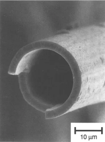
All annealing conditions used for the fiber burnout, except for the one at 600 °C, produced ZnO tubes with a large length-to-diameter ratio (Fig. 3). Coated fiber lengths up to 3 cm could be annealed without fracture, resulting in tubes with length-to-diameter ratios as high as 1500. The 23 /mm inside diameter of the annealed tubes directly corresponds to the 23 /mm diameter fiber substrate. No significant shrinkage or change in the microstructure of the coating was observed in the an-nealed samples as compared to the as-coated fibers. Figure 4 shows the columnar microstructure of the tube
I I
FIG. 2. Debye—Scherrer x-ray diffraction pattern for a polyester fiber with a 5 n-m ZnO coating. The nonuniformity of the 002 ring results from the [002] radial texture of the coating.
2738 J. Mater. Res., Vol. 9, No. 11, Nov 1994
https:/www.cambridge.org/core/terms. https://doi.org/10.1557/JMR.1994.2737
Communications
FIG. 3. SEM image of ZnO tube after burning out the polymer fiber fugitive phase by annealing in air at 550 °C for 2 h.
wall, which is typical for both as-coated and annealed tubes. The radial [002] preferred orientation of the columnar grains does not appear to be affected by the burnout process since XRD patterns of the tubes are sim-ilar to the pattern for an as-coated fiber in Fig. 2. A very smooth inside wall is observed; the surface roughness, which is on the 1 nm scale, is likely to be determined by the surface roughness of the polymer fiber substrate. In comparison, the outside surface of the tube exhibits roughness on the 100 nm scale (Fig. 4) and some larger outgrowths in the 1 /xm size range, as shown in Fig. 5. Since the outside surface roughness is controlled by both the roughness of the substrate and shadowing effects, the outside surface roughness increases with increasing wall thickness. The large outgrowths are probably generated from hillocks or defects on the polyester fiber surface, which causes exaggerated grain growth due to enhanced shadowing effects.
The feasibility of using a fugitive phase technique to produce three-dimensional hollow structures in the micron size range has been demonstrated and has re-sulted in the production of ZnO microtubes with a 23 /u,m inside diameter. Tubes up to 3 cm in length have been prepared, although it should be possible to produce tubes with lengths longer than 3 cm or even continuous tubes with the proper processing equipment arrangement. Such long continuous tube structures will undoubtedly have many micromechanical applications, particularly since ZnO possesses piezoelectric and pyroelectric ca-pabilities. Since the tube walls exhibit a [002] radial texture, the application of internal and external electrodes will make it possible to actuate the inside diameter, outside diameter, and length of the tube. Similarly, strains produced by stresses on the inside and the outside of the tube could also be measured.
'•?}*£..•
•-FIG. 4. SEM image of the ZnO tube wall, which consists of columnar
grains with [002] preferred orientation along the lengths of the FIG. 5. SEM image of the surface of a ZnO tube after the polymer columns. fiber burnout.
J. Mater. Res., Vol. 9, No. 11, Nov 1994 2739
https:/www.cambridge.org/core/terms. https://doi.org/10.1557/JMR.1994.2737
Communications
ACKNOWLEDGMENTS
This research was supported by the Optical Sciences, Applications, and Technology, Priority Program of the Board of The Swiss Federal Institute of Technology.
REFERENCES
1. K. T. Brown and D. G. Flaming, Advanced Micropipette
Tech-niques for Cell Physiology (John Wiley and Sons, Chichester,
England, 1986).
2. J. Scott, Hollow Fibers (Noyes Data Corporation, Park Ridge, NJ, 1981).
3. H. Labelle, J. Cryst. Growth 50, 8 (1980).
4. P. Brake, H. Schurmans, and J. Verhoest, Inorganic Fibres
and Composite Materials (Pergamon Press, Oxford, England),
pp. 35-47.
5. M. Aizawa, Y. Nakagawa, Y. Nosaka, N. Fujii, and H. Miyama, J. Non-Cryst. Solids 124, 112 (1990).
6. R. A. White, J. N. Weber, and E. W. White, Science 176, 922 (1972).
7. K. Rittenmyer, T. Shrout, W.A. Schulze, and R.E. Newnham, Ferroelectrics 41, 189 (1982).
8. M. Miyagi, A. Hongo, Y. Aizawa, and S. Kawakami, Appl. Phys. Lett. 43, 430 (1983).
9. Y. Matsuura and M. Miyagi, J. Appl. Phys. 68 (11), 5463 (1990). 10. Y. Matsuura and M. Miyagi, J. Appl. Phys. Lett. 61 (14), 1622
(1992).
11. Polyesther Fiber, TYP 158, Rhdne-Poulenc Viscosuisse SA, Emmenbriicke, Switzerland.
12. Cement Universal, Merz and Benteli SA, Niederwangen, Switzer-land.
13. Diffstak, model 150, Edwards High Vacuum International, West Sussex, England.
14. Mass flow controller, type 825; Multichannel flow controller, model 1605, Edwards High Vacuum International, West Sussex, England.
15. High accuracy pressure transducer, type 120; Power supply/ readout, type 510, MKS Instruments, Andover, MA.
16. STM 100/MF thickness/rate monitor, Sycon Instruments, East Syracuse, NY.
17. 100 mm magnetron source, Edwards High Vacuum International, West Sussex, England.
18. Zn metal, 99.99% pure, CERAC Incorporated, Milwaukee, WI. 19. MDX IK Magnetron Drive, Advance Energy Industries, Inc., Fort
Collins, CO.
20. Debye-Sherrer x-ray camera, Huber, Rimsting, Germany. 21. Stereoscan 360 scanning electron microscope, Cambridge
Scien-tific Instruments Ltd., Cambridge, U.K.
2740 J. Mater. Res., Vol. 9, No. 11, Nov 1994
https:/www.cambridge.org/core/terms. https://doi.org/10.1557/JMR.1994.2737