HAL Id: hal-01707143
https://hal.archives-ouvertes.fr/hal-01707143
Submitted on 13 Feb 2018HAL is a multi-disciplinary open access archive for the deposit and dissemination of sci-entific research documents, whether they are pub-lished or not. The documents may come from teaching and research institutions in France or
L’archive ouverte pluridisciplinaire HAL, est destinée au dépôt et à la diffusion de documents scientifiques de niveau recherche, publiés ou non, émanant des établissements d’enseignement et de recherche français ou étrangers, des laboratoires
Size-Specific Spin Configurations in Single Iron
Nanomagnet: From Flower to Exotic Vortices
Christophe Gatel, Francisco Javier Bonilla, Anca Meffre, Bénédicte
Warot-Fonrose, Etienne Snoeck, Bruno Chaudret, Lise-Marie Lacroix, Thomas
Blon
To cite this version:
Christophe Gatel, Francisco Javier Bonilla, Anca Meffre, Bénédicte Warot-Fonrose, Etienne Snoeck, et al.. Size-Specific Spin Configurations in Single Iron Nanomagnet: From Flower to Exotic Vortices. Nano Letters, American Chemical Society, 2015, 15 (10), pp.6952 - 6957. �10.1021/acs.nanolett.5b02892�. �hal-01707143�
1
Size specific spin configurations in single iron
nanomagnet: from flower to exotic vortices
C. Gatel1,*,F.B. Bonilla2, A. Meffre2, E. Snoeck1, B. Warot-Fonrose1,B. Chaudret2, L.-M.
Lacroix2, T. Blon2,*
1
Centre d’Elaboration de Matériaux et d’Etudes Structurales, CEMES-CNRS, 29 rue Jeanne
Marvig, B.P. 94347, 31055 Toulouse, France
2
Laboratoire de Physique et Chimie des Nano-Objets, LPCNO, UMR5215 INSA-UPS-CNRS,
Université de Toulouse; Institut National des Sciences Appliquées, 135 avenue de Rangueil,
31077 Toulouse, France
Abstract
The different spin configurations in the vicinity of the single-domain/vortex transition are
reported in isolated magnetic nanoparticles. By combining chemical synthesis, electron
holography in a dedicated transmission electron microscope and micromagnetic simulations, we
establish the “magnetic configuration vs size” phase diagram of Fe single-crystalline nanocubes.
Room temperature high resolution magnetic maps reveal the transition between single-domain
and vortex states for Fe nanocubes from 25 to 27 nm respectively. An intermediate spin
configuration consisting of an <111> vortex is for the first time evidenced.
Keywords: magnetic configuration, electron holography, vortex state, single domain state,
nanocube.
The magnetic configuration in a magnet of a given volume results from the minimization of
the total energy, involving magneto-crystalline anisotropy, exchange and magneto-static
energies. As a result, three typical magnetic configurations can be encountered in a magnetic
material at the remnant state: (i) a uniform arrangement of magnetic moments, i.e. a
single-domain (SD) configuration (Fig. 1(a)); (ii) a vortex (V) state in which external spins rotate to
achieve a flux closure, while in the vortex core, spins tilt out-of-plane (Fig. 1(b)); and (iii) a
multidomain state dealing with adjacent domains in large volumes. Well characterized in bulk
materials, the multidomain configuration is now pursued in magnetic nanowires to benefit from
domain wall motion for data storage in the so-called magnetic racetrack memories.1,2 While
single domain configuration is often optimized for applications requiring hard magnetic
3 applications such as hyperthermia or drug delivery7 to minimize the stray field around the
particle and thus prevent magnetic aggregation,8 or in spin-torque vortex-oscillator devices for
microwave signal-processing applications.9
In these contexts, one needs to evidence at room temperature the single-domain limit
separating SD and V states. The determination of this single-domain limit in a single
nanoparticle has been largely investigated numerically and is predicted to be in the order of
several exchange lengths, i.e. from 15 to 25 nm depending of the material.10-15 Though spin
configurations were experimentally determined in different nanomagnets such as nanowires,2,16,17
nanocubes,18,19 nanospheres,20-22 faceted nanoparticles,23 or nanorings,24-25 no result has been
reported on the experimental determination of the critical size, even for nano-objects with the
simplest geometries. This is mainly due to the limited sensitivity and resolution of existing
experimental techniques, which do not allow studying isolated nanomagnets of size close to the
expected transition. For instance, magnetic force microscopy 26,27 and photoemission electron
microscopy,28 which are classically used for magnetic thin films characterizations, display spatial
resolution of few tens of nanometers, far above the single domain limit. Low-temperature
spin-polarized scanning tunneling microscopy with spatial resolutions of few angstroms has been used
to characterize vortex configurations in elongated Fe islands of several hundreds of nm.29 Vortex
states have also been studied in Fe nanocubes of several tens of nm by off-axis electron
holography (EH) in a transmission electron microscope (TEM), with few nanometers of
resolution.18,19
EH is a powerful TEM interferometric method which consists on superimposing a highly
coherent electron beam that has interacted with an object and the surrounding electromagnetic
any field, the so-called “reference wave”. The analysis of the resulting interference pattern (i.e.
the electron hologram) allows the extraction of the phase shift between the reference beam and
the one that has interacted with the magnetic induction through the Aharonov-Bohm (A - B)
effect. The analysis of the magnetic phase image provides a quantitative mapping of the
magnetic field with a spatial resolution down to one nanometer. It is important to note that the
measured magnetic phase shift corresponds to a projection and an integration of all in-plane
magnetic field contributions along the electron path. Numerical simulation are generally
necessary to take into account the two dimensional projection of the three dimensional field. (see
Supplementary information). Experiments have been performed on an EH dedicated TEM fitted
with a cold field emission gun to achieve a high phase shift sensitivity, and a special corrected
Lorentz mode allowing a magnetic field-free sample environment and a spatial resolution down
to 0.5 nm (see Supporting Information).
Studying the SD/V transition required a peculiar sample preparation. Isolated nano-objects are
mandatory to prevent any influence of dipolar interactions on the magnetic configuration of the
object under study. Moreover, defect-free nanomagnets with controlled and reproducible
magnetic properties should be sought to allow accurate modeling and comparison with
experimental investigations. Finally, simple shape, such as cubes, should be favored to control
the nano-object orientation once deposited at the surface. Indeed, in contrast to spheres,20 cubes
can lay on a surface along one of their face, orienting their crystallographic structure for TEM
observations and their magnetization for magnetic imaging.
Single crystalline Fe nanocubes (NCs) were synthesized in solution following an
organometallic chemistry approach (details in the Supporting Information). By varying the
5 performed on powders of NCs showed that, whatever the size, the Fe NCs exhibit the bulk
saturation magnetization (MS).30 Fe nanocubes of 27 ± 4 nm were deposited on carbon grid by
drop casting leading to assemblies of few NCs down to isolated NCs as shown in Figure 1(c-d).
High resolution TEM experiments confirm that these nanocubes exhibit a single-crystal
body-centered cubic (bcc) structure with {100} facets and <100> edges, the latter being their
magnetocrystalline easy axis (Fig. 1(d), Supporting Fig. S1). A ∼1 nm layer of iron oxide shell (most likely Fe3O4), results from air exposition during sample transfer. The determination of the
specific shape and magnetic volume being of key importance for accurate measurements of the
SD/V limit, the thickness (noted c) of the NCs should be investigated. TEM images give only
access to the lateral lengths (a, b) of the NCs, with about 1 nm accuracy in EH configuration.
Therefore, we evaluated the squareness distribution, defined as a/b ratio, and assumed a similar
thickness to length c/a ratio to finally estimate the NC thickness. Squareness distribution of 17%
(Supporting Fig. S1) led to a thickness estimation c = (1 ± 0.17)×a. For comparison with
experiments, micromagnetic simulations were performed using the 3D OOMMF package,31
considering single crystalline Fe NCs with {001} facets using Fe bulk values for exchange,
saturation magnetization and magnetocrystalline anisotropy (details in the Supporting
Several iron nanocubes have been studied by EH to observe the most probable magnetic
configurations. As the NCs have never been exposed to any magnetic field, the measured
configurations correspond to virgin remnant states. Three different configurations will be
detailed hereafter. Figure 2(a) and Figure S2 of the Supporting Information display the
holograms obtained for two different Fe cubes. Figure 2(b) shows the magnetic phase shift map
obtained on a 27×26×(27±5) nm3 nanocube after separation of the electrostatic contribution (see
Supporting Information). For such NC, the magnetic induction curls within the nanocube,
evidencing a vortex configuration whose core axis is along the [001] direction parallel to the
electron beam, referred to from now on as <001> vortex (V<001>). To corroborate these Figure 1. Schematic 2D view of (a) a single-domain and (b) a vortex spin
arrangement in a square magnetic element. (c) Transmission electron microscopy
(TEM) micrograph of Fe nanocubes. (d) High resolution TEM micrograph of a
7 observations, micromagnetic simulations were carried out on a corresponding NC of 29.53 nm3,
i.e. a 27.53 nm3 Fe NC surrounded with a 1nm Fe3O4 shell. Starting from a random spin
configuration, the simulation leads to a stable V<001> state as shown in Figure 2(e). From the
calculated magnetization and dipolar field, the total induction B in and outside the NC is
obtained and further integrated along the electron beam direction, i.e. the z direction. The
simulated magnetic phase shift image of Fig. 2(d) is then calculated thanks to the
Aharonov-Bohm relation using the in-plane components of B (details in Supporting Information). A very
good agreement between simulated and experimental phase shift maps is obtained, as evidenced
Figure 2. Magnetic electron holography vs. micromagnetic simulations of an isolated iron
nanocube of 27×26×(27±5) nm3. (a) Experimental hologram and (b) resulting magnetic
phase shift map. (c) Cosine of the experimental phase image corresponding to the magnetic
induction flux lines (see Supporting Information). The inset color wheel indicates the
direction of the magnetic induction. (d) Simulated magnetic phase shift map calculated
from micromagnetic simulations (dashed box indicates the cube position). (e) 3D view of
the magnetization obtained at the equilibrium state for a simulated cube of 29.53 nm3 (27.53
nm3 Fe core and a 1nm Fe3O4 shell). (f) Comparison of experimental and simulated profiles
9 position).
Focusing on the uniform spin arrangement expected below the SD/V limit, a NC of
24×26×(25±4) nm3 was investigated by EH as shown in Figure 3. The resulting magnetic phase
shift map with superimposed isophase contours is reported in Figure 3(b) to evidence the
magnetic flux lines. While these lines are fairly aligned within the cube, they tend to curl outside
in order to close the induction flux. At first sight, such features could be characteristic of a SD or
a V state along the in plane [010] direction. Micromagnetic simulations are then mandatory to
unambiguously distinguish between both configurations. Starting from a randomly spin
orientation in a cube of similar dimension, a SD state is obtained (Fig. 3(e)). A [010] vortex state
is artificially stabilized numerically using a slightly reduced exchange constant for comparison.
The two profiles are then compared with the experimental one (Fig. 3(f)). The drastic difference
of amplitude clearly evidences that SD is experimentally observed. A closer look at the vicinity
of the edges reveals that the magnetization flares out, both on simulated and experimental
mappings (Figure 3(b-d)). Such an effect is due to the inhomogeneity of the stray field and
makes this SD state usually referred as flower state.Erreur ! Signet non défini.,Erreur ! Signet
non défini.,Erreur ! Signet non défini.,Erreur ! Signet non défini. Another example of the
experimental evidence of a SD-flower state is also given in Supporting Information Figure S3 for
a 22×26×(24±4) nm3 cube. While a SD state has been previously reported within an isolated
faceted 50 nm diameter magnetite crystal,Erreur ! Signet non défini. it is the first time that a
SD-flower state is quantitatively and unambiguously evidenced in a single nanomagnet as small
Figure 3. (a) Electron hologram of a 24×26×(25±4) nm3 Fe nanocube and (b) corresponding
magnetic phase shift map with 78 mrad isophase contours (as for (e)). (c) Cosines of the
experimental phase corresponding to the magnetic induction flux lines. The inset color
wheel indicates the direction of the magnetic induction. (d) Magnetic phase shift map
calculated from micromagnetic simulations (dashed box indicates the cube position). (e)
3D view of the calculated magnetization obtained at the equilibrium state for a simulated
cube of a 24×26×24 nm3 Fe nanocube (22×24×22 nm3 Fe core surrounded with a 1 nm
Fe3O4 shell). (f) Comparison of experimental and simulated profiles along the arrows
11 comparison, the dashed line represents the profile obtained for a vortex configuration
whose the core is aligned along the [010] (i.e. y) direction of the NC.
Figure 4(a) shows a hologram recorded on an intermediate NC of 25×27×(26±4) nm3. The
extracted magnetic phase image presents a complex pattern which cannot be directly interpreted
(Figure 4(b)). The micromagnetic simulation of a cube of similar dimension obtained after
relaxation of a randomly spin orientation leads to a complex spin arrangement (Fig. 4(c)): its
projection along the cube diagonal reveals that spins curl around <111> direction (Fig. 4(d)).
This complex configuration is therefore a vortex, the core axis of which is aligned along the
diagonal of the cubes, referred hereafter as vortex <111> (<111> vortex). The calculated
magnetic phase shift map extracted from this simulated spin arrangement is reported in Fig. 4(e)
and presents the same general pattern as its experimental counterpart. On Fig. 4(f), a quantitative
comparison of linear profiles evidences a good agreement between experimental and simulated
profiles and evidencing the sensitivity of the EH-TEM setup, even for such a weak phase shift
(less than π/5 in the NC). A second example of a <111> vortex is given in Supporting Fig. S4.
These experimental configurations and the size at which they are observed have to be
compared with theoretical results. Considering nanocubes with uniaxial anisotropy, numerical
studies have shown that the single-domain limit separates SD and <001> vortex states without
the presence of an intermediate state.Erreur ! Signet non défini.,Erreur ! Signet non
défini.,Erreur ! Signet non défini. Calculations on Fe nanospheres with a cubic anisotropy
proposed a hard-axis-oriented vortex as an intermediate state for diameters between 25 and 40
anisotropy demonstrate that the three SD, <111> and <001> vortices are stable configurations. In
order to address more precisely the stability of each configuration, we performed additional
micromagnetic simulations. We restricted our study to Fe NCs exhibiting ferromagnetic
behaviour at room temperature, i.e. for mean length above 15 nm, but with a size lower than the
domain wall width (64nm for Fe).
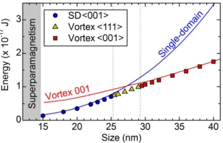
In a first approach, simulations were carried out on NCs for which the initial spin
configuration, uniform SD or V<001>, was imposed. The resulting energies were calculated for
different NC sizes and reported in Figure 5 as blue and red lines for the SD and V<001>
respectively. Magnetic transition between SD and V<001> should then occur at 27 nm, i.e.
around 11 times the Fe exchange length (lexFe = 2.4nm). SD minimizes the exchange energy for
small sizes, at the expense of magneto-static energy which scales with the volume. In contrast,
V<001> minimizes the magneto-static energy but leads to an increase of the exchange energy
due to the spin disorientations between “vertical” spins in the core and “horizontal” spins at the
cube periphery. When the cube size is reduced, angle between neighboring spins from the center
13 Figure 4. (a) Hologram and (b) corresponding magnetic phase shift map of a 25×27×(26±4)
nm3 Fe nanocube with 62 mrad isophase contours. (c) 3D view of the simulated magnetization
in a perfect Fe nanocube of 263 nm3 (243 nm3 Fe core with a 1 nm Fe3O4 shell) starting from
an initial random distribution of moments. (d) Projection of (c) along the [11-1] direction of
the cube illustrating a vortex configuration with a core-axis parallel to the <111> direction,
i.e. one of the main diagonal of the cube. (e) Calculated magnetic phase shift map with same
isophase contours as (b) obtained from the simulation of a 263 nm3 cube (dashed box indicates
the cube position). (f) Comparison of experimental and simulated profiles along the arrows
This first fairly simple simulation approach was corroborated by a second method into which a
random spin configuration is originally introduced. Relaxation of the spins leads to the stable
configuration and the corresponding energy is plotted as dots in Figure 5. Below 25 nm (above
29.5 nm), stable SD (V<001>) configurations are observed. This is consistent with previous
measurements of V<001> states in 30 nm Fe nanocubes.18 As expected, energies are identical for
vortices with [100], [010] and [001] core axis. For intermediate sizes, between 25.5 and 29 nm,
simulations evidence <111> vortex as the most stable configuration, the four equivalent
directions [111], [111], [111] and [111] leading to similar energies. In this size range where they
are observed experimentally, V<111> have a lower energy than SD and V<001> configuration.
This can be understood with the following argument: the core axis aligned along a <111>
direction permits to accommodate along a NC diagonal the spin disorientation between the
vortex core and its periphery. Thus the V<111> allows balancing exchange and magneto-static
interactions at the expense of the magnetocrystalline energy which remains quite low in Fe.
Figure 5. Calculated magnetic energy of ferromagnetic iron nanocubes (including a 1nm
Fe3O4 shell) as a function of the total cube size (range 15-40 nm). The energies were
15 Experimentally we evidenced SD, <111> and <001> vortex states for cubes of roughly 25, 26
and 27 nm size respectively, confirming the sharp but sequential transition between these three
configurations when increasing the NC size. The size range at which we observed each state was
however not as large as suggested by the phase diagram of Fig.5. Particularly, the V<001>
vortex of Figure 2 is not expected for the measured NC size of 27×26×(27±5) nm3, therefore we
compare it with the smallest calculated NC for which V<001> is the ground state (29.5nm3).
This discrepancy might have several origins. First, the real nanocube thickness remains unknown
and only a combined use of high-resolution tomography and HRTEM on a same NC could allow
refining the NC dimension and could be carried out in our equipment. Secondly, the magnetic
parameters used for simulation are those deduced from macroscopic measurements on NC
assemblies and that correspond to the bulk ones. These values are however mean values of a
given distributions and therefore the magnetic parameters may slightly differ from one cube to
another. However the major conclusion is that, even if slight deviations from bulk prediction
may occur, the quantitative comparisons between simulated and experimental profiles allow
determining unambiguously the presence of a given magnetic configuration. Thus, these results
demonstrate that the single-domain limit separating SD and V states is effectively in the range
predicted by simulations using bulk magnetic parameters and, in addition, involves the
appearance of an intermediate spin arrangement.
Here we report the spin configuration phase diagram in size-controlled single iron
nanomagnets combining state of the art of magnetic electron holography experiments and
micromagnetic simulations. High sensitivity imaging explicitly reveals how three different spin (dots) and frozen SD (blue line) or Vortex <001> (red line) initial states is reported.
arrangements can be stabilized within a 3 nm window, evidencing the key importance of
nanometric size control of magnetic nanoparticles. Moreover, it gives a deeper understanding of
the single domain limit, which is more complex than expected with the appearance of a
previously unreported <111> vortex state. Such a measurement opens the door to fine magnetic
control of nano-objects which will find applications in fields as wild as spintronics devices,
information storage or hyperthermia.
Supporting Information
Details of the chemical synthesis of Fe nanocubes, structural characterization, electron
holography experiments and analysis, 3D micromagnetic simulations, histograms of nanocube
size and squareness ratio, additional experimental evidences of SD flower, <001> and <111>
vortices. This material is available free of charge via the Internet at http://pubs.acs.org.
Corresponding Author
* Blon, T.: [email protected]
* Gatel, C.: [email protected]
Notes
17 Acknowledgements
The authors acknowledge M. Respaud for fruitful discussion and careful reading of the
manuscript. C.G., E.S., B.W. acknowledge the French National Research Agency under the
"Investissement d'Avenir" program reference No. ANR-10-EQPX-38-01" the "Conseil Regional
Midi-Pyrénées", the European FEDER for financial support within the CPER program and
the European Union under the Seventh Framework Program under a contract for an
Integrated Infrastructure Initiative Reference 312483-ESTEEM2. This work was supported by
the French national project EMMA (ANR12 BS10 013 01) and the French microscopy network
METSA.
References
1
Parking, S.S.P.; Hayashi, M.; Thomas, L. Science 2008, 320, 190-194
2
Biziere, N.; Gatel, C.; Lassalle-Balier, R.; Clochard, M.-C.; Wegrowe, J.-E.; Snoeck, E. Nano
Lett. 2013, 13, 2053-2057
3
Terris, B.D.; Thomson, T. J. Phys. D: Appl. Phys.2005, 38, R199-R222
4
Liakakos, N.; Blon, T.; Achkar, C.; Vilar, V.; Cormary, B.; Tan, R.P.; Benamara, O.;
Chaboussant, G.; Ott, F.; Warot-Fonrose, B.; Snoeck, E.; Chaudret, B.; Soulantica, K.; Respaud,
M. Nano Lett. 2014, 14, 3481-3486
5
Poudyal, N.; Ping Liu, J. J. Phys. D: Appl. Phys. 2013, 46, 043001 1-23
6
Gandha, K., Elkins, K., Poudyal, N., Liu, X., Ping Liu, J. Sci. Rep., 2014, 4, 5345 1-5
7
8
Yang, Y.; Liu, X.-L.; Yi, J.-B.; Yang, Y.; Fan, H.-M.; Ding, J. J. Appl. Phys. 2012, 111,
044303 1-9
9
Pribiag, V.S.; Krivorotov, I.N.; Fuchs, G.D.; Braganca, P.M.; Ozatay, O.; Sankey, J.C.; Ralph,
D.C.; Buhrman, R.A. Nat. Phys. 2007, 3, 498-503
10
Schabes, M.E. ; Bertram, H.N. J. Appl. Phys. 1988, 64, 1347-1357
11
Rave, W.; Fabian, K.; Hubert, A. J. Magn. Magn. Mater. 1998, 190, 332-348
12
Hertel, R.; Kronmüller, H. J. Magn. Magn. Mater. 2002, 238, 185-199
13
Muxworthy, A.R.; Williams, W.; Roberts, A.P.; Winklhofer, M.; Chang, L.; Pósfai, M.
Geochem., Geophys., Geosyst. 2013, 14, 5430-5441
14
Betto, D.; Coey, J.M.D. J. Appl. Phys. 2014, 115, 17D138 1-3
15
Kakay, A.; Varga, L.K. J. Appl. Phys. 2005, 97, 083901 1-4
16
Snoeck, E.; Dunin-Borkowski, R.E.; Dumestre, F.; Renaud, P. ; Amiens, C.; Chaudret, B.;
Zurcher, P. Appl. Phys. Lett. 2003, 82, 88-90
17
Akhtari-Zavareh, A.; Carignan, L.P.; Yelon, A.; Ménard, D.; Kasama, T.; Herring, R. ;
Dunin-Borkowski, R.E.; McCartney, M.R.; Kavanagh, K.L. J. App. Phys. 2014, 116, 023902 1-11
18
Snoeck, E.; Gatel, C.;; Blon, T.;; Carrey, J.; Respaud, M.; Chaudret, B. Nano Lett. 2008, 8,
4293-4298
19 Lacroix, L.-M.; Lachaize, S. ; Hue, F.; Gatel, C.; Blon T.; Tan, R.P.; Carrey, J.;
19
20
Hÿtch, M.J.; Dunin-Borkowski, R.E.; Scheinfein, M.R.; Moulin, J.; Duhamel, C.; Mazaleyrat,
F.; Champion, Y. Phys. Rev. Lett. 2003, 91, 257207 1-4
21
He, K.; Ma, F.-X.; Xu, C.-Y.; Cumings, J. J. App. Phys. 2013, 113, 17B528 1-3
22
Varón, M.; Beleggia, M.; Kasama, T.; Harrison, R.J.; Dunin-Borkowski, R.E.; Puntes, V.F.;
Frandsen, C. Sci. Rep. 2014, 3, 1234 1-5
23
Thomas, J.M.; Simpson, E.T.; Kasama, T.; Dunin-Borkowski, R.E. Acc. Chem Res. 2008, 41,
665-674
24
Beleggia, M.; Lau, J.W.; Schofield, M.A.; Zhu, Y.; Tandon, S.; De Graef, M. J. Magn. Magn.
Mater. 2006, 301, 131-146
25
Singh, D.K.; Krotkov, R.; Tuominen, M.T. Phys. Rev. B 2009, 79, 184409 1-9
26
Shinjo, T.; Okuno, T.; Hassdorf, R.; Shigeto, K.; Ono, T. Science 2000, 289, 930-932
27
Amos, N.; Ikkawi, R.; Haddon, R.; Litvinov, D.; Khizroev, S. Appl. Phys. Lett. 2008, 93,
203116 1-3
28
Fraile Rodríguez, A.; Kleibert, A.; Bansmann, J.; Voitkans, A.; Heyderman, L.-J.; Nolting, F.
Phys. Rev. Lett. 2010, 104, 127201 1-4
29
Wachowiak, A.; Wiebe, J.; Bode, M.; Pietzsch, O.; Morgensten, M.; Wiesendanger, R. Science
2002, 298, 577-580 30
Lacroix, L.-M. ; Lachaize, S.; Falqui, A.; Respaud, M.; Chaudret, B. J. Am. Chem. Soc. 2009,
31
Donahue, M.J.; Porter, D.G. OOMMF User's Guide, Version 1.0, Interagency Report NISTIR