HAL Id: cea-02509186
https://hal-cea.archives-ouvertes.fr/cea-02509186
Submitted on 16 Mar 2020
HAL is a multi-disciplinary open access
archive for the deposit and dissemination of
sci-entific research documents, whether they are
pub-lished or not. The documents may come from
teaching and research institutions in France or
abroad, or from public or private research centers.
L’archive ouverte pluridisciplinaire HAL, est
destinée au dépôt et à la diffusion de documents
scientifiques de niveau recherche, publiés ou non,
émanant des établissements d’enseignement et de
recherche français ou étrangers, des laboratoires
publics ou privés.
To cite this version:
F. Lemont, S. François, M. Marchand, M. Mabrouk, K. Poizot. Innovative plasma routes for liquid
radwaste processing. GLOBAL 2015 - 21st International Conference & Exhibition, Sep 2015, Paris,
France. �cea-02509186�
INNOVATIVE PLASMA ROUTES FOR LIQUID RADWASTE PROCESSING
F.Lemont, S.François, M.Marchand, M.Mabrouk, K.PoizotCEA, DEN, DTCD, SCDV, LPIC, F-30207 Bagnols-sur-Cèze, France
Abstract – Nuclear fuel cycle operation, production and application of radioisotope in biological investigation, industry, research….are as much sources of liquid radioactive waste. Some of them are currently treated to immobilize their radionuclides before final repository when others are waiting for suitable processes.
For several years, the CEA has worked to adapt plasma technology to liquid treatment. Among the followed technological tracks, two have been considered as promising because rapid and very effective. The first, involving aerial inducted plasma torch, ensures the treatment by feeding the liquid in the hearth of the inductive coil, directly into the plasma plume. The second, involving submerged non transferred plasma torch into which the liquid is also fed, has the particularity to use underwater plasma in order to avoid corrosion and to extend the range of waste that can be treated.
The aim of this paper is to provide a description and the performances of these two processes displaying large potentialities through their originality. Several radwastes could find their outlet thanks to these two new routes.
I. INTRODUCTION
Liquid radwastes largely produced by industrial or research activities, have the particularity to be various and dispersed through different sites and facilities. Some of them are called “orphan waste” because of the lack of processes able to treat them when others have specific outlet.
For several years, the CEA has been developing different kinds of processes to stabilize radioactive solid wastes. If some of them could be used to treat liquids fed along with the solids, the difficulties encountered in mixing liquids and solids led to explore new routes of treatment involving oxygen plasma technology because of its very high oxidation potential.
Two different options are presented in the present paper. The first involving aerial inducted plasma torch, has been essentially developed to destroy pure organics free of mineral load such as scintillation liquids. The second, involving submerged blown plasma torch, has been developed to destroy liquids that may contain a large variety of minerals and heteroatoms such as phosphorus, sulfur, chlorine, fluorine, …
II. WHICH LIQUID ARE CONCERNED? Some of the liquids generated by nuclear activities have efficient treatment processes. For instance, the high level fission products coming from reprocessing plants are vitrified with the goal of producing stable glass eligible for long term storage.
Others, more varied, less radioactive or produced in smaller quantities, still have to wait for technical development. This is the case for example for the 212 m3 (data 2009) of various aqueous solutions (containing toxics
such as Be, Ni, Cr; strong acid or strong alkali, 3H- bearing, …) stored over the different sites of the CEA.
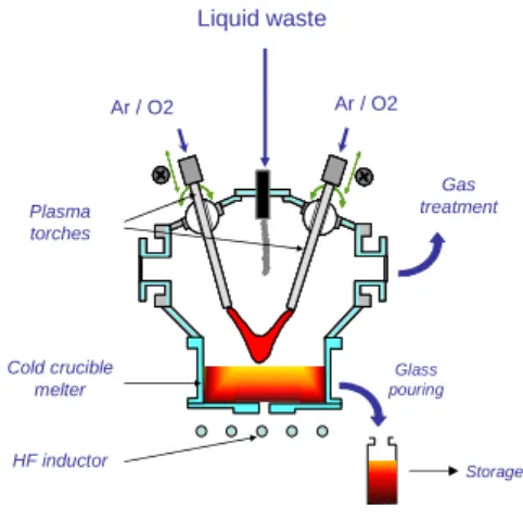
After neutralization, theses liquids could be concentrated by evaporation under vacuum or not. Afterward, their minerals could be processes to produce a stable matrix like a glass or cement. Some advanced and available technologies such as SHIVA process could be qualified to ensure the direct vitrifying of the solution. The liquid directly fed on the glass bath can be evaporated between the radiating surface (near 1000°C) and the transferred arc plasma torches as depicted in figure 1.
Fig. 1. Schematic diagram of the SHIVA process
Among others liquids, there lie organics that need to be mineralized. These organics are many and varied.
They include pure halogenated organic liquids containing C, H, O , Cl (X= Cl or F) such as 3H-14C-bearing liquids used in biological application (imaging, scanning, …). The IDOHL process has been developed to treat these kinds of liquids that does not contain mineral charges except Cl or F. Liquid waste Ar / O2 Ar / O2 Gas treatment Glass pouring Storage Plasma torches Cold crucible melter HF inductor
They also include more complex chemicals with more heteroatoms (Cl, F, P, S, …) along with dissolved minerals or other suspended compounds. The ELIPSE process has been developed to ensure the destruction of those varied liquids likely to contain various minerals.
III. THE IDOHL PROCESS
Thermal plasma can be used for waste destruction; several studies have proposed the thermal plasma process for the destruction of organo-halogenated wastes [1-3]. Compared with other methods, thermal plasmas have unique characteristics such as rapid decomposition with high throughput, fast startup and shutdown, and high energy delivery (the proposed energy values are substantially higher than the activation energies of conventional chemistry).
The IDOHL process (French acronym for “Installation de Destruction d’OrganoHalogénés Liquides” ) has been patented [4] in order to destroy liquid radwaste by using inductively coupled thermal plasma. This type of plasma has several advantages as the geometry of the torch which allows the treatment not only of gases but also of liquids without prior evaporation (it is not always easy to place liquid directly in the plasma because of the viscosity of plasma medium), the absence of electrodes, the kinetics and the extended residence time.
In its first stage [4], this process used water as combustion agent in order to avoid the forming of hazardous off gases such as phosgene (COCl2). To increase its capacity, water was changed for oxygen used under overstoichiometric condition, [5].
Plasma torch and feeding system
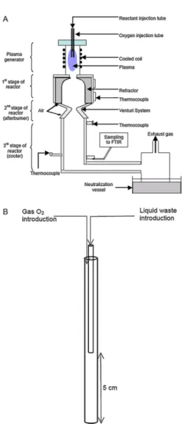
The experimental facility implemented at Marcoule is shown schematically in Figure 2. The plasma source is an induction plasma torch with high-purity argon as the plasma and sheath gas. It is supplied by a high-voltage power supply coupled with a high-frequency (64 MHz) transmitter supplying a 7-turn copper induction coil to generate the plasma. The maximum power rating is 4.5 kW. The plasma is confined in a quartz tube with an inside diameter of 35 mm. The gas is ionized at high temperature (over 6000 K for argon plasma).
The oxygen is injected in the reactor via an alumina tube (4 mm inside diameter). Then, liquid is introduced via an alumina tube (1.5 mm inside diameter); the two tubes form a coaxial cylindrical injection system (Fig. 5B).
Fig. 2. (A) Schematic diagram of IDOHL process. (B) Detailed experimental setup ofthe injection system.
Reactor
The torch is coupled with a chemical reactor consisting of three main parts (Figure 5A):
- The first is the reaction stage itself (341 mm long, 43 mm inside diameter), comprising a refractory alumina shell to prevent temperature gradients, inside a water-cooled stainless steel jacket. When empty (without added reactants), the reactor design allows gas temperatures of about 1200 K to be reached at the output of this stage.
- The second part of the reactor is the afterburner stage consisting of a Venturi system. Turbulent mixing is obtained by injecting two airstreams to enrich the medium in oxygen in order to fully
oxidize the residual carbon to CO2 and hydrogen
to H2O, as well as to sharply reduce the
temperature of the gas mixture from the first stage. A thermocouple at the output of this stage indicates temperatures of around 500 K for no load operation.
- The third stage of the reactor is a stainless steel tube 300 mm long and 43 mm in inside diameter. The reaction products are further quenched in this column, after which they are analyzed before being released to the atmosphere. The entire process operates under slight negative pressure (≤ 30 mbar) to prevent leakage.
Highly halogenated compound treatment
After building and upgrading, the process efficiency has been assessed through the treatment of highly halogenated compound such as CHCl3 commonly
called chloroform.
After starting the argon plasma and stabilizing the temperatures in the reactor stages, oxygen is injected in the reactor to establish fully oxidizing conditions. When the temperatures stabilize again, liquid chloroform is introduced via the inner alumina tube As the chloroform passes through the tube already containing oxygen, the two reactants are mixed well before they enter the plasma.. As the system is hot, combustion begins in the lower part of the injection tube.
Various flow rates for both CHCl3 and O2 have been
tested for the qualification of the process.
Temperatures in the process are monitored at the bottom of the reactor together with gas sampling. A continuous analysis is performed thanks to a Fourier transform infrared spectrometer (Gasmet™ DX4000, Finland). This is capable of simultaneously analyzing more than 30 gaseous species, notably the following in our assessment: CHCl3, HCl, CO2, H2O, CO, COCl2.
As Cl2 is not analyzed by the IR spectrometer, its
for-mation was identified by bubbling a fraction of the reactor off-gas stream through a 1 M sodium hydroxide solution, followed by a reaction with KI. The iodine generated by the reaction between KI and
chlorine was titrated with an aqueous solution of sodium thiosulfate, Na2S2O3.
The off-gas was then trapped in an aqueous sodium hydroxide solution to ensure a clean process. In the case of chloroform destruction, the main reason for caustic scrubbing is to absorb and thus neutralize the acidity due to the major chlorinated species (Cl2 and
HCl) generated. The scrubbing solution pH is automatically adjusted when it drops below 9.
During treatment, temperature stabilized around 950°C in the reactor for a plasma power of 4.5kW in the high frequency generator (meaning around 2kW in plasma)
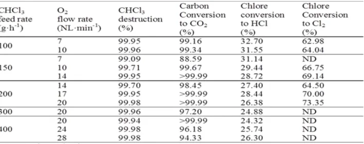
The efficiency of CHCl3 destruction versus feed rate
of CHCl3 and O2 are listed in Table I.
Our experimental results showed negligible CO concentrations in the reaction off-gas (below 0.001%); CO2 was thus the main carbon species measured by
FTIR. The measured CO2 production can therefore be
a suitable performance indicator for this process. Indeed, column IV in Table I shows very satisfactory conversion of the initial carbon. The conversion results are generally better than 90%, indicating that the initial carbon is effectively converted to CO2.
It can be seen that between 25% and 33% of the initial chlorine was converted to HCl (Table I, column 5). For each chloroform injection rate, the overall percentage of Cl converted to HCl tends to diminish when the oxygen flow rate increases (i.e. for increasing excess oxygen). The same be-havior was reported by Huang et al. [6] for plasma de-composition of C2HCl3 in the presence of oxygen.
Most of the Cl atoms thus remain in the form of Cl2
molecules what has been confirmed thanks to bubbling and chemical analysis described above. The test results are shown in the last column of Table I. Molecular chlorine is indeed formed after the decomposition of CHCl3; the chlorine balance shows that, regardless of
the test conditions, more than 95% of the initial chlorine is finally present as HCl and Cl2. The 5 %
missing can be due to the measurement uncertainties.
Efficiency of CHCl3 treatment
We present on the Table II, the maximum quantities of phosgene obtained for the various CHCl3 injection rates. The maximum release rate was 1g.h-1 for waste injected at a rate of 400g.h-1, and the maximum concentration was 30ppm. Current French legislation requires that gaseous effluents comply with limits depending on the maximum permissible hourly flow rate: in the case of phosgene, the maximum rate is 10g.h-1, but if this value is exceeded the release concentration limit is 1ppm [7]. Table II clearly shows that in this study the maximum phosgene formation rate before scrubber was well below the limit. Although chlorine was formed here during chloroform destruction, we have already indicated above that CO was fully oxidized and absent from the reactor. The elimination of carbon monoxide is unquestionably an advantage in preventing the formation of toxic chlorine compounds.
TABLE II
Phosgen production during treatment of CHCl3
Concerning another aspect of the off-gas quality, Cl2 and HCl formed by decomposition of CHCl3 are toxic gases
that must not be released untreated into the atmosphere. One technique for simultaneous absorption of these gases is to absorb them in an aqueous solution by direct reaction with excess sodium hydroxide to form sodium hypochlorite and sodium chloride. These reactions can be considered complete as long as the pH remains basic, as it was the case in our experiments.
Conclusion
The effective destruction of chloroform – a model of liquid organochlorine – is proven using argon inductively plasma with oxygen as oxidant to obtain complete and safe destruction. The results demonstrate that the destruction of CHCl3 is highly effective (near-100% decomposition regardless of the test conditions) with relatively high energy efficiency (the decomposed waste mass per kWh can reach 100g) and a satisfactory destruction rate (up to 400g.h-1). Furthermore, the off gas composition meets with regulations.
Based on these results, the system presented in this paper can be considered as a clean technology for the destruction of liquid organohalogens with the advantage of direct liquid waste injection into the plasma without any prior evaporation or treatment. These results are of considerable importance for industrial applications knowing that the feed rate can be increased by using a more powerfull plasma torch (10, 50, 100kW…)
The process described in this paper will be in a near future, used for the treatment of liquids contaminated by 14C and 3H. The transfer operations are currently in progress.
IV. THE ELIPSE PROCESS
To incinerate liquid waste with an organic fraction of nearly 100 %, the oxidation potential of a plasma torch operating with oxygen was combined with the concept of a submerged plasma jet. In this case, the plasma is no more an inductive plasma but a non transferred arc plasma. The advantage of submerged thermal plasma treatment is the very high temperature obtained in an overall cold reactor, which limits corrosion problems; the high concentration of oxidizing radicals in the oxygen plasma and the intense UV radiation allow almost instantaneous combustion of the organic matter. Recombination reactions are minimized by rapid quenching. Turbulence induced in the water by the plasma jet ensures satisfactory gas–to–liquid transfer and trapping in solution of the waste mineral fraction liable to contain radionuclides. In this operating mode the solution not only maintains the process at the ambient temperature, but also ensures most of the functions of an off-gas treatment system: cooling, filtration, and neutralization.
The development studies rapidly validated the concept, and tests were conducted to liquids considered problematic and widely represented in the nuclear industry. A tributylphosphate (TBP)/dodecane mixture with a high Lower Heating Value (LHV) and high phosphorus content was selected for the initial qualification of the concept. This mixture is widely used in extraction processes during reprocessing operations and becomes a liquid waste stream contaminated by radionuclides that must be mineralized before they are conditioned.
Concept and design
The concept of the ELIPSE process consists of implementing a plasma torch at the bottom of a reactor full of water. When organics are fed in the hearth of oxygen plasma, they burn in the nozzle of the torch and form off gases being quenched in the water.
In this way, water is used as off gas treatment: It cools, filters and scrubs the gases. Gas treatment is then replaced by a water treatment system involving an heat exchanger and a filtering system.
In this operating mode the solution not only ensures the gas treatment but maintains the process at the ambient temperature. This is an extraordinarily important and pioneering provision to prevent corrosion.
The concept of the process is shown in figure 3.
Fig. 3. The ELIPSE process.
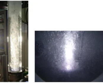
The design was validated by tests as shown in Figure 4 where one can see plasma working under a water column.
Fig. 4. Working underwater plasma
Process evaluation with treatment of TBP/dodecan
The liquid is injected at the rate of 3L/h into a stage attached to the anode outlet
The first experiment revealed an efficient destruction of the liquid upper than 99%. However, it was found that the amount of CO was pretty high, upper than 6%.This was
Cheminée Filtre Liquides organiques Torche à plasma d’arc Filtre Echangeur Ar O2 NaOH Purge Cheminée Filtre Liquides organiques Torche à plasma d’arc Filtre Echangeur Ar O2 NaOH Purge Stack HEPA Filter Filter Exchanger Organics Plasma torch
due to a very rapid quenching of the off gases. Actually, if the jet penetrates directly into solution, the quenching rate estimated by [8] is around 2.107K.s-1. It is fast enough to frieze the conversion of CO into CO2.
Calculation for lower quenching rates, 106 and 105K.s-1, clearly shows that reducing the cooling rate ofthe gas before it is quenched in solution will diminish the CO content at the moment of quenching, and therefore in the off-gas stream.
To ensure the best combustion, a new plasma nozzle has been design. The objective was to rapidly reduced the temperature of the gases together with increasing the residence time of the gases . This new nozzle includes:
- The liquid injection stage into which the waste is fed in the plasma hearth
- A solution reinjection stage into which the solution coming from the reactor is fed. The vaporization of the aqueous solution insures a rapid but non total gas cooling
- A refining stage into which the residence time of the gases is sufficient to complete oxidation (0.1ms).
Figure 5 gives a picture of the plasma nozzle
Fig. 5. Plasma nozzle divided into different sections
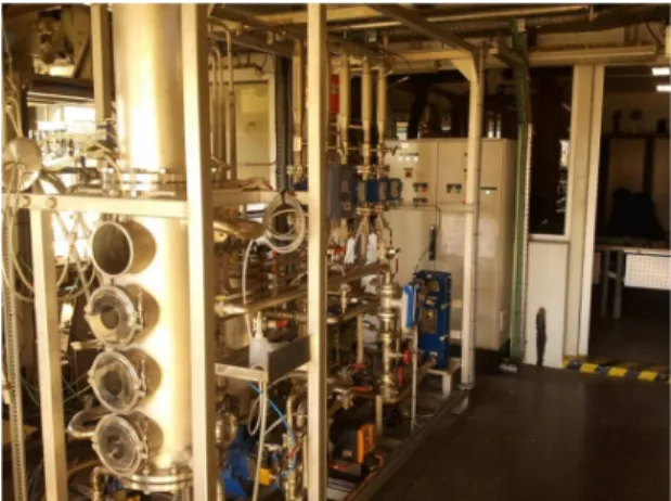
This is with this upgrading that a mockup has been built at the research center of Marcoule (Figure 6) for a feed rate upper than 3L.h-1.
Fig. 6. ELIPSE mockup
New experiments have been performed using TBP/ dodecane solution with a feed rate of 3L.h-1. The CO content did not exceed 0.17 %, while the CO2 content of the off-gas stream remained relatively constant at about 23%: this value corresponds to the complete conversion of carbon present in the waste into CO2 in gas form.
Hence the combustion efficiency is about 99.3 %. At the end of the test, the TOC in solution was measured: 4.67 g compared with 1797 g in the feed stream. The destruction efficiency was therefore 99.7 %.
In addition, the solution samples were analyzed by ion chromatography and using the Hach_Lange cuvette test system to determine the total phosphorus concentration. These results show that the measured quantity phosphorus can be estimated at 81.7 g, whereas 83.4 g were introduced. The phosphorus capture yield is thus 98 %. After testing, the reactor and components were removed for inspection. While stainless steel behavior was satisfactory in the solution rich in phosphoric acid, copper surfaces were strongly attacked—especially the external hard-soldered joint of the injection stage. The copper stages were replaced by Inconel 600 stages: this overcame the corrosion problem.
Due to the low thermal conductivity of Inconel compared with copper and the power density in the combustion stage—about 80 kW in 1 cm3—the thermal energy could
not escape, leading to the destruction of the injection stage. Possible solutions include stages with integral cooling, or nickel-coated copper stages.
Three additional evaluations
One very big issue is the ability of the process to destroy very different liquid. How efficient is the treatment ? What is about corrosion?
To answer these questions, three experiments have been carried out with the ELIPSE process into which the copper
parts were changed for cooled Inconel parts. The feed rate have been lowered to 2L.h-1 in a first step:
- TBP/Dodecan: Treatment efficiency of 99.90% with a phosphorus capture of 98%. Inspection of the different parts of the process showed a very good behavior of the new Inconel nozzle without corrosion.
- Trichlorethylene: Treatment efficiency of 99.96% with a chlorine capture of 99%. Inspection of the different parts of the process showed a very good behavior of the new Inconel nozzle without corrosion.
- Perfluorinated oil: Treatment efficiency of 99.8% with a fluorine capture of 94.1%. Inspection of the different parts of the process showed a very good behavior of the new Inconel nozzle without corrosion.
Conclusion
The work presented an overview of the scientific and technological progression leading to the design of a submerged plasma process for the treatment of organic liquids. After demonstrating that cooling the gas before it penetrates into the reactor guarantees a composition with an acceptable CO/CO2 output ratio, tests were conducted to
evaluate the destruction of a TBP/dodecane mixture. The tests substantiated the process efficiency: the TOC destruction efficiency always exceeds 99 % regardless of the type of waste, and the trapping yields for inorganic materials such as chlorine are near 100 %, within the measurement uncertainty margin. Only fluorine shows a lower capture that has to be investigate.
The very good behavior of the process regarding treatment efficiency and maybe above all the lack of corrosion opens considerable perspectives for the destruction of various liquids. We can then already conclude that the process now being developed has very strong potential. Versatility, compactness and robustness are the terms that best describe it.
REFERENCES
1. U.S. Environmental Protection Agency, Greenhouse Gases and Global Warming Potential Values, April 2002.
2. J.C. Lou, Y.S. Chang, Thermal oxidation of chloroform, Combust. Flame 109 (1997) 188–197.
3. K.A. Föglein, P.T. Szabo, I.Z. Babievskaya, J. Szépvolgyi, Comparative study on the decomposition of chloroform in thermal and cold plasma, Plasma Chem. Plasma. Proc. 25 (2005) 289–302.
4. E.Meillot, D.Guenadou, Device and Method for Destroying Liquid, Powder, or gaseous Waste using an inductively coupled Plasma. Patent WO 2005/080873 5. F.Lemont, K.Poizot, Method and device for thermal
destruction of organic compounds by an induction plasma. Patent US 2012/0277515
6. L. Huang, T. Fujita, X. Zhang, H. Matsuda, Influences of H2 and O2 and in situ Ca(OH2) absorption on
nonthermal plasma decomposition of trichloroethylene in N2, Chem. Eng. J. 124 (2006) 81-87.
7. Arrêté 2002 05-02 relatif à la pollution de l’air art. 2 Journal Officiel de la République Française 5 mai 2002.
8. Alekseev NV, Samokhin AV, Agafonov KN, Tsvetkov YV (1999). Oxidation of organic compounds in water under injection of thermal plasma jet. Paper presented at the 14th international symposium of plasma chemistry, Prague, Czech Republic, August 2–6