COMPACT TOKAMAK IGNITION REACTOR FOR
ALPHA PARTICLE HEATING AND BURN CONTROL STUDIES
L. Bromberg, D.R. Cohn and J.E.C. Williams
November 1978
Compact Tokamak Ignition Reactor for Alpha Particle Heating and Burn Control Studies
L. Bromberg, D. R. Cohn and
J.
E. C. WilliamsM.I.T. Plasma Fusion Centertt and
Francis Bitter National Magnet Laboratoryt
Plasma Fusion Center Report RR-78-12
Work supported by U.S. D.O.E. Contract ET-78-S-02-4646 t Supported by U.S. D.O.E
Supported by N.S.F.
Presented at the 1978 Winter Meeting of the American Nuclear Society, Washington D.C., Nov 12-16.
Abstract
Design considerations have been developed for a tokamak ignition test reactor whose objectives are to demonstrate ignition and burn control of ignited plasmas. It may also be possible to use this device to study the problems associated wih long pulse operation ( ~ 20 r,) of an ignited plasma. A key feature of the design is the use of copper TF plates of Bitter construction in order to accomodate the relatively high stresses required for a compact device. This plate design also allows the use of simple inorganic insulation between the TF coils, extending the lifetime of the machine under ignited operation to ~ 500,000 burn-s. The flat top of the toroidal field magnet is - 20 s. Adiabatic compression in major radius of a neutral beam heated tokamak plasma reduces the beam energy required for adequate penetration permitting the use of 160 keV D* beams. It may also be possible to use adiabatic adjustment of major radius to control thermal runaway after ignition has been achieved. An illustrative design has been developed for a device with a magnetic field on axis of the compressed plasma in the range 8 - 10 T. For a circular ignited plasma with <0> ~ 2.4 %
the magnetic field on axis is 9.2 T. The major radius of the center of the magnet bore is 1.65 m and the magnetic field at the center of the magnet bore is 7.3 T. The major radius of the compressed plasma is 1.3 m and the minor radius is 0.52 m. The compression ratio is ~ 1.5. The machine requires 14 MW neutral beam power if the empirical scaling law is valid at the high temperatures. 6 beam ports, each with 0.2 m2
, provide enough access for the neutral beams. The fusion power produced at ignition is 70 MW. A 150 MW power supply is enough to drive the TF coil and the auxiliary systems. Compression requires pulsing 70 MJ in the equilibrium field system. The energy required for compression is provided by inductive storage coils.
I. Introduction
The objectives of the compact tokamak ignition reactor are:
0 to demonstrate ignition, determining the values of plasma density, temperature and size required for ignition
* to study alpha particle physics in a regime where alpha particle heating dominates over all other heating
0 to study the control of an ignited plasma over an extended period of time (5-10 sec, 10-20 energy confinement times)
In addition it may be possible to study the physics of long pulse operation, including refueling. and impurity buildup problems.
Ignition is defined as the condition in which the fusion power trapped in the plasma is sufficient to balance the plasma losses. The fusion reaction thus becomes self-sustaining. The high values of
Q
- Fusion power/Auxiliary Heating power needed for a pure fusion tokamak reactor are obtained by operating at or near ignition. Ignited operation also obviates potential problems associated with steady state auxiliary heating.A compact copper magnet ignition test reactor is attractive because it affords the possibility
of meeting these goals in the mid 1980s at moderate cost. Furthermore, the use of compression to reduce neutral beam requirements for penetration should make it possible to obtain centrally peaked beam deposition profiles with 160 key Do beams. These beams should be available by the time that the machine is operational. In addition, the beam pulse length required for heating to ignition is reduced by operation at high densities and by the use of compression. It should be possible to heat to ignition in ~ s.
The development of a compact device is facilitated by a Bitter plate magnet design which allows high stresses. The Bitter plate design also allows the use of inorganic electrical insulation for
Page 2
the TF coil. The use of inorganic insulation makes possible a prolonged life time of the machine operating under ignited conditions without the use of neutron shielding between the plasma and the TF coil.
In the present paper we present design parameters for a compression boosted high field ignition test reactor. The parameters presented here were developed as part of a collaborative design effort with the IPP Laboratory at Garching and the CNEN Laboratory at Frascati 1,.
Page 3
I. Physics of Ignited Operation
Ignition is defined as the conditions in which the fusion reaction is self-sustaining. At ignition, the fusion power which remains in the plasma is sufficient to balance the plasma energy losses. The deuterium-triium fusion reaction produces energy according to the relation
D +T - (a + 3.5 Mev) +(n + 14.1Mev)
At ignition alpha particles are confined in the plasma, and serve as the heating source needed to maintain the- plasma temperature. That is, the alpha power is greater than or equal to all of the power lost by the plasma.
In order to confine the alpha particles, it is necessary that these particles have orbits that do not leave the plasma. In order to achieve this, it is necessary that the product of the plasma current
and the aspect ratio A - Rp/ap be lp A > 7.5 106 A . 3
The amount of alpha particle production depends upon the ion temperature. However, the electrons play an important intermediary role in the energy balance. For electron temperatures of relevance for an ignition. test reactor, most of the alpha particle energy is deposited in the electrons.
Since some of this energy must be transferred collisionally to the ions to maintain the feedback loop, it is necessary that the electron temperature be larger than the Ion temperature.
The ignition requirement can be expressed in terms of n, 'r, where no is the central density and r, is the global energy confinement time. The value of this parameter at ignition is shown in
Figure 1 as a function of temperature in the absence of impurities and assuming that the electron and ion temperatures are equal and that the density and temperature profiles are parabolic. At any
point above the ignition curve, the heating input from the fusion process is larger than the power loss. It can be shown that in the range of central plasma temperatures 9 keV < To < 20 keV,
(n2o Tedign 7"1
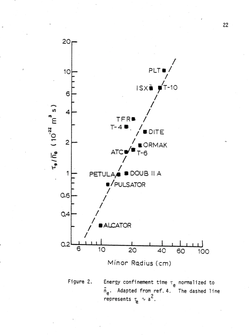
In order to make some predictions about ignition conditions in tokamaks, we assume that the energy confinement time of the plasma is determined by the empirical scaling law
Page 4
(r,)emp - 3.8 10-19 n. (2
where n. is the electron density in cm- at the center of the machine, ap is in cm and r, is in s. -(The q112 dependence of the scaling law 4 has been supressed in view of recent experiments in ALCATOR 5 and PULSATOR 6). The data on which this scaling is based is shown in Figure 2, adapted from reference 4. Recent experimental results in PLT indicate that the. electron energy confinement time may improve with increasing temperature
If the energy loss mechanism is given by the empirical scaling law or by a modified scaling law where r, increases with temperature, then the plasma ignition state is unstable to temperature perturbations. This can be seen in Figure 3, where the power loss and fusion heating inputs are shown as a function of temperature. Because of the absence of an inverse temperature dependence in
e,emp ,a small increase in temperature over the ignition temperature results in an increase in the
fusion power which is greater than the increase in the total plasma losses. Therefore the plasma is heated even further and is thermally unstable. A fusion reactor operating at ignition for more than a time on the order of a few energy confinement times will need thermal stability control. This control may be provided automatically by the plasma if the energy confinement time decreases sufficiently with increasing temperature. In order for the ignition point to be stable in the absence of impurities, the local dependence of r, on T. has to be r, T0 n, where n < -1 . This inverse temperature dependence might be caused by balloning modes .
If automatic thermal stability is not obtained, then active thermal control must be supplied. Three schemes which have been proposed for active thermal stability control are:
adiabatic compression and decompression induced toroidal ripple'0
induced magnetic islandsi1
The pulse length of the compact tokamak ignition reactor is long enough so that the plasma achieves self-consistent temperature and density profiles. An important ignition physics question is to determine whether these profiles result in unstable states. Disruptions of an ignited plasma could
Page 5
result in large heat loads to first wall and large energy losses in the superconductor of a fusion reactor.
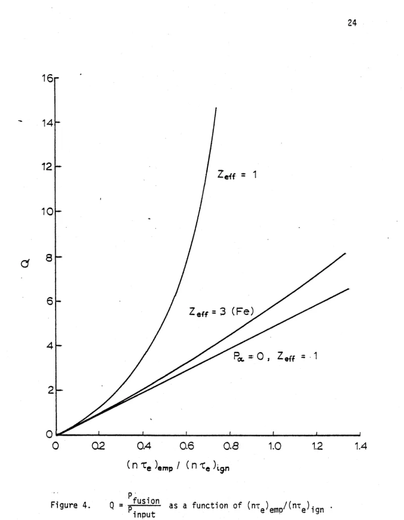
Although it may be possible to obtain large values of
Q
by using the plasma as a power multiplier, the required values of n. -r, and T. are close to those required for ignition. This is shown in Figure 4. (This figure does not include the beam-plasma and beam-beam reactions; for a review of neutral beam driven systems, see ref. 12). Furthermore, steady state heating of tokamak reactors may present significant problems in non-ignited tokamaks. For steady state neutral beam heating, for example, there may be problems with the required pulse lengths, beam penetration requirements, neutron streaming down the beam line and gas loads from the neutral beam source.Page 6
III. Design of a Compact Tokamak Ignition Reactor
The plasma minor radius of a tokamak plasma is given by 1A q(a
ap - ~ = B 1A)(2
where BT is the toroidal field on axis and ap) is the safety factor. Tokamak experiments indicate that q(ap) > 2 .13 For a given value of I A set by alpha confinement requirements3, high magnetic
fields result in small minor radius. High magnetic fields also result in large plasma densities which, 4
according to the empirical scaling law, will reduce the minor radius required for ignition . From the empirical scaling law, (n ap)I, "(n, r,) . Therefore, ap ~ 1/ no.
Neutral beams provide the best means of plasma heating at present time. In order to reduce the neutral beam energy required for penetration, adiabatic compression in major radius 14 is used to increase the parameter n, re after heating of the initial plasma with neutral beams. According to the. empirical scaling law for the energy confinement, the value. of nor, for the final plasma is related to the value of nor, of the initial plasma by 15
(nor)f (nrd,(3)
where C is the compression ratio in major radius. The neutral beam energy required to heat a plasma to ignition is shown in Figure 5 as a function of the compression ratio [adapted from reference 15). The upper curve is for beam deposition profiles that are strongly peaked in the center, while the lower curve is for moderately peaked deposition profiles. Near perpendicular injection is assumed. A compression ratio on the order of 2 is required in order that near state-of-the-art (~120 keV) neutral beams can be used. For neutral beam energies ~ 160 keV, the compression ratio is reduced to ~1.5 .
High density operation coupled with compression also results in fast heating times, reducing the neutral beam pulse length required. Noting that in the precompression stage the fusion power is relatively small compared with the auxiliary power required, then the heating time scales as
Page 7
EP1asma no k To Vol (n re (no r 1(4)
"beam no To Volke e C C nof
Here we have used (3) and the fact that during major radius compression, no! - C2 n
Two margins of safety are defined to indicate the probability of achieving ignition. The
margin of safety with respect to beams is defined as
s no reemp, max beampn (5)
Mibeams (ordlign
where (no.r)empmax beam Pen is the value of the confinement quality parameter at the maximum density- resulting in peaked* beam deposition profiles and (nor,)ig is shown in Figure 1. This
margin of safety is mainly determined by the beam energy, the compression ratio and the plasma temperature (see Appendix A). From the empirical scaling law and from the fact that for beam penetration the beam energy scales as Wb., (no ap), then Mlbeams ~W C3 W .
The margin of safety with respect to beta is defined as
M /bra (no 'redemp, max beta B4 a2 a2 (6)
(n e)gn
Here (nor,emp, max. beta is the value of the confinement parameter evaluated at the largest value of
07-* 07 is defined as the spatial average of the ratio of the plasma kinetic pressure to the magnetic field pressure:
nj k Tj(7)
BT- 12AO
The largest value of OT is determined by instabilities. Here it is assumed that Ocrit, bal 1 0.09
Ocrif 7702 (8)
#critfal'is the maximum # allowed by balloning modes and it is assumed that Ocritbal 3% for an aspect ratio of 3 and for q(ap) - 2.5 . This is 'in agreement with present predictions of the balloning mode effects8,16 . KO is introduced to indicate the uncertainities in the value of 9crit . In this case,
(1 t4 )(
Page 8
The margin of safety of beams, Mlbeams can be reduced by two effects: impurities and degradation of the energy confinement time with increasing temperature. Impurities reduce the beam penetration and increase the value of (no r,ign at a given temperature. If r, < (r,p there is a decrease in the value of (n, y,) achievable with a given beam energy for fixed deposition profiles. It is desired that the degree of beam penetration be similar to that in present successful neutral beam heating experiments. Edge heating (heating deposition profile with an off axis peak) may result in increased impurity buildup; higher temperatures near the edge of the plasma and high energy charge exchange neutrals may result in increased impurity generation. Furthermore, edge heating is inefficient and leads to increased beam power requirements. Edge heating also results in increased Or because of flat temperature profiles. A desirable value of MIbeams is ~ I in the absence of impurities. That is, it is chosen such that in the most optimistic conditions the resulting beam deposition profile is peaked. For 160 keV beams and T~ 15 keV, C 1.5 for MI&ms 1.
The margin of ignition for beta. Mleta provides safety against the presence of impurities, decrease in r, with temperature and uncertainities in the value of Ocrit. Recent results in PLT indicate that r, does not deteriorate (and may in fact increase) with increasing plasma temperatures for central electron temperatures up to 3.5 keV. Furthermore, several tokamaks have operated at very low levels of impurities. Hence, the largest uncertainity appears to lie in the value of Ocrit. Experimental determinations of ocrit have not yet been made. Most of the theory has been linear ideal MHD theory which predicts a 07 ~ /A scaling. Equation (8) is used mainly to compare
different types of machines. The value of. M4beta desired is therefore somewhat arbitrary, depending on what is assumed for (8). In the present study, it is assumed that M4bt - I for
K- 1.5.
Illustrative machine parameters that provide both of these margins of safety are shown in Table I, shown for Ko = I . The stored energy in the TF magnet is 640 MJ. The parametric study used to arrive at these parameters is included in Appendix A.
Page 9
the ALCATOR C design 17, TF - 2.1 108 Pa (30 kpsi) when Mibta- I with KO - 1.5 Although somewhat smaller outer radii of the TF coil can be obtained by running at higher magnetic field than that shown in Table I, the stored energy in the TF magnet and its dissipation power increase. (see Appendix A)
In Table Ilthe changes of the machine parameters for KO 1.5 and Ko 2 are shown. It should be noted that the gross energy confinement has been assumed to be given by the empirical scaling law. If the iohns observe neoclassical confinement, then the margins of ignition have been underestimated (as rn ~ 3 (r,),,p ) for the cases in Tables I and I1.
The time required to heat the precompressed plasma is - I s and the burn pulse can be as long as 20 r, for Ko - 1.5 . The burn pulse length is limited by heating of the TF coil by both ohmic dissipation and neutron heating from the fusioning plasma. The pulse is assumed to terminate when the peak temperature in the inertially cooled TF coil reaches 4000K. Figure 6 shows an
schematic diagram of the TE coil with the precompressed and final plasmas.
The properties of the vertical field are shown in Table 111. It is estimated that the peak power during compression is ~ 400 MW and that the energy stored in the vertical field will increase during compresion by~ 70 MJ. In appendix B the vertical field is considered in detail.
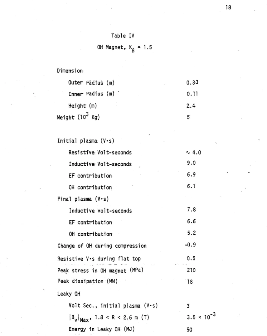
The magnetic fluxes required to drive the plasma are shown in Table IV. Also shown there are the fluxes produced by the OH and the vertical field at both the initial and final plasma positions. It is interesting to note that during compression the OH flux has to be decreased. This decrease makes it possible to drive the OH to larger heat dissipation during the short periods of time prior to the initiation of the discharge and just before compression. It is the heat dissipation rather than'. the stresses what limit the flux swing through the OH. Also shown are the characteristics of a leaky OH transformer. Although not needed it would allow the possibility of having near zero current in the OH transformer when the plasma is at the final position, simplifying the feedback mechanism if active thermal control is needed. The OH system is studied in more detail in Appendix C.
Page-10
The parameters of the T7 coil are shown in Table V. The TF coil design is of Bitter type. The'magnet is initially cooled to liquid nitrogen temperature and is inertially cooled during the pulse. The peak power of the TF supply is 150 MW. Cooling the magnet down to LN 2 temperature after
the end of a 18 s burn pulse requires 29000 liters of liquid nitrogen. The use of inorganic insulators (such as mica) for the TF coil would allow ~ 500000 burn-s, that is, 50000 pulses 10 s long.
Details about the TF coil are discussed in Appendix D.
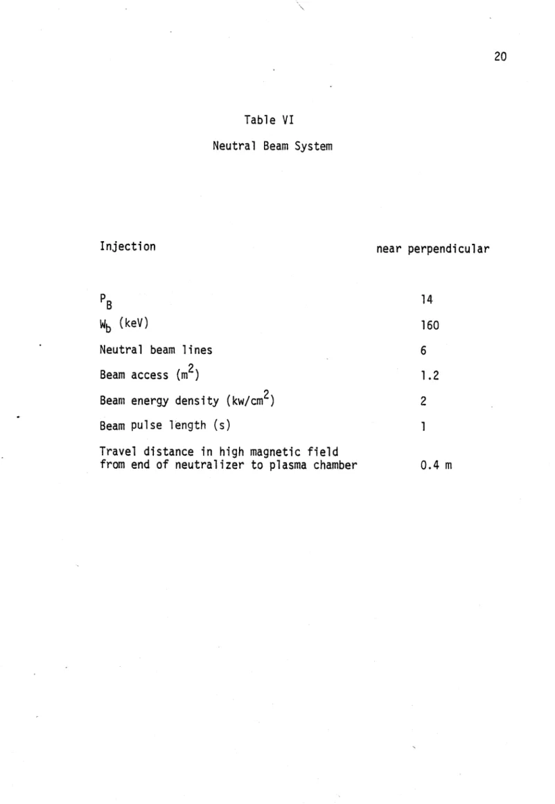
The neutral beam power required is ~ 14 MW if there is no degradation of the energy confinement time at the higher temperatures. Assuming that the power density per unit area is 2 kW/cm2, then in order to inject ~14 MW of beams, 0.7 m2 of neutral-beam access is necessary.
Six ports, each with 0.2 m2 are more than sufficient. To prevent the escape of fast injected ions, the magnetic field ripple must be kept small. The plasma current of the initial plasma is 2.5 MA and A 3.. This should provide good confinement of the injected 160 keV ions12.
A port design is shown in Figure 7. The ripple decreases to very low levels at the position of the compressed plasmra. The beam energy, power requirements and port dimensions are shown in Table VI. In Appendix D details about the port and the neutral beam system are included.
The beam port has been overdesigned to allow penetration of cooling lines. The first wall
will require cooling during the pulse because of the large alpha power. Neutron heating of the vacuum wall is negligible. Preliminary design I shows that a stagnant water filling of a double wall vaccum vessel will provide enough thermal mass to result in a temperature excursion of < 500K.
Page 11
IV. Conclusions
Using high stress copper Bitter magnet technology, it is possible to design a compact (major radius-~ 1.7 m) ignition reactor. In order to facilitate alpha particle dominated heating and burn control studies, the engineering design of the compact ignition reactor would differ from that of TFTR and JET in the following ways:
The toroidal field flat top would be ~ 20 s, which allows for maintaining the ignited plasma for ~ 30 energy confinemment times.
The Bitter design would facilitate the use of inorganic insulation such as mica, which allows for 500,000. burn-s . This number of burn-s would be one to two orders of magnitude greater. than that of TFTR and JET which utilize organic insulation. The use of compression and high density operation would allow for rapidly heating to
ignition.
The compact tokamak ignition reactor is based upon conservative extrapolation of physics and technology and could be operational in the mid 1980's.
Page 12
Acknowledgemnents
This work was performed as part of a collaborative effort between the Max-Planck Institut fur PlasmaPhysic at Garching, the CNEN Laboratory at Frascati and MIT. The authors wish to acknowledge very useful conversations with H. Becker, D. L. Kaplan, M. Kaufman, A. Knobloch, K. Lackner, D. B. Montgomery; M. Olmstead, J. Schultz, C. Weggel and R. Wilhelm.
Page 13
References
L. Bromberg, D. R. Cohn and J. E. C. Williams, MIT Plasma Fusion Center Research Report 78-4 (April 1978); H. Becker et. al, MIT Plasma Fusion Center Report 78-10 (September 1978)
2 Compact Ingnition Experiment Internal Status Report, prepared by Max Plank Institut fur Plasmaphysik, Garching and the Divisone Fusione of CNEN, Frascati (1978)
3 D. Post, private communication; D. G. McAlees, Oak Ridge National Laboratory Report
ORNL-TM-4661 (1974)
4 D. R. Cohn, R. R. Parker and D. L. Jassby, Nucl Fusion 16 31 (1976); D. L. Jassby, D. R. Cohn and R. R. Parker, Nucl Fusion 16 1045 (1976)
5 ALCATOR group, private communication
6 PULSATOR group, private communication
7 H. P. Eubank, Bull Am. Phys. Soc. 23 7 (1978)
8 M. Okabayashi, private communication
9 K. Lackner, in Annual Controlled Fusion Theory Conference, Gatlinburg, Tn, April 1978
10 R. J. Goldston and D. L. Jassby, in Proceedings of the 3rd International Meeting on the Theoretical and Experimental Aspects of Heating Tokamak Plasmas, Grenoble 1978, paper
1-8
It K. Lackner, private communication
Page 14
13 D. Overskei, Bull. Am. Phys. Soc. 2.3 7 (1978)
14 H. P. Furth and S. Yoshikawa, Phys. Fluids 13 2593 (1970)
15 D. R. Cohn, D. L. Jassby and K. Kreischer, Nucl Fusion 18 1255 (1978)
16 M. A. Todd et a, Princeton PLasma.Physics Laboratory Report MATT-14.. (1978)
17 C. Weggel _LL, in Proceedings of the 7th Symposium on Engineering Problems of Fusion
Research, Knoxville, Tn, October 1977
18 H. Haselton, private communication
19 V. S. Mukhovatov and V. D. Shafranov, Nucl. Fusion 11605 (1971)
20 C. P. Corvino, General Magnaplate Corp., private communication
21 TFR group, Nucl. Fusion 18 1271 (1978)
15
Table I
Ignited Plasma Parameters Base Case; K 1 <T >ign 2.9% C 1.5 RF (m) 1.3 aF (m) 0.52 BT (T) 8.3
(aCu
)max
(MPa) 170wmag (MJ) 640
q a 2.5
I (MA) 3.3
n
)(m-3
6 x 10²⁰T (keV) 15
Plasma shape circular
(-rEemp (s) 0.6
tpulse /(Te emp 30
Wb (keV) 160
Table II
Illustrative Ignition Device Parameters: Extra Margin
1.5 2.4 <t >ign BT (T)
u
(acu)max (MPa) Ip(MA) 9.2 210 3.7 WMag (MJ) 16 2.0 2.0 9.9 240 4.0 790 91017 Table III Parameters of EF System 1.5 R dB -B dR Initial energy (MJ) Final energy (MJ)
Increase in energy during compression (MJ)
Tcomp (s)
Peak Power (MW)
Peak Dissipation power (17s pulse)(MW)
0.4 28 95 70 0.15 , 400 15 Inductive Storage Power Supply
Table IV OH Magnet, K 1.5 Dimension Outer ridiu (m) Inner radius (m) Height (m) Weight (TO3 Kg) Initial plasma (V-s) Resistive- Volt-seconds Inductive Volt-seconds EF contribution OH contribution Final plasma (V-s) Inductive volt-seconds EF contribution 0H contribution
Change of OH during compression Resistive V-s during flat top Peak stress in OH magnet (MPa) Peak dissipation (MW)
Leaky OH
Volt Sec., initial plasma (V-s) IBYIMax, 1.8 < R < 2.6 m (T) Energy in Leaky OH (MJ) 0.33 0.11 2.4.
5
4.0 9.0 6.9 6.1 7.8 6.6 5.2 -0.9 0.5 210 18 3 3.5 x O- 3 50 1819
Table V
TF Magnet, K = 1.5
Dimensions
Height (m)
Outer Radius, R out(m) Inner Radius, r ohm(m)
Major Radius of center of magnet bore (m) B at center of magnet bore (T)
Field at final plasma (T) Peak field (T)
Total TF current (A) Stored energy (J) Stresses (Pa)
Circumferential
Vertical tensile at inboard trunk, ave Bending stresses, max
Resistive power (at 77*K)
Resistive power (after 17S flat top) Energy dissipation per 17s pulse
Electrical (GJ)
Nuclear (17s ignited operation)(GJ) Peak magnet temperature, 17 s flat top
Weight (10 3 Kg)
Liquid nitrogen evaporation per 17 s pulse (k) 2.4 2.95 0.35 1.65 7.3 9.2 17.5 60.4 x 10⁶ 790 x 106 0.8 x 10⁸ 2.9 x 10⁸ 2.9 x 10⁸ 43 MW 130 MW 1.6 1.2 4000 K 320 29000
20
Table VI
Neutral Beam System
Injection near perpendicular
PB14
Wb (keV) 160
Neutral beam lines 6
Beam access (m 2) 1.2
Beam energy density (kw/cm2) 2
Beam pulse length (s) 1
Travel distance in high magnetic field
co 0N 0 0, *1~* 2T
o>
.-aE
a
a_ C OIL.a~U
(0 cs)
0u) E-a1 4-o 0. Q J-- ( -J o & ~0 L o 'e 0 <- 0 C .4 C O 4n - --r- A CA " C *v --0 E 0 A 4- --PLTU
/
ISX6
T-10
TFRW/
T-4Sr
/
/ /DITE
-T
&aORMAK
ATCW/OT-6
PETULA
0
DOUB
11A
§/PULSATOR
-/
EALCATOR
10 II I I I Ii i20
40
60
100
Minor
Radius
(cm)
Figure 2. Energy confinement time r normalized to
n * Adapted from ref. 4. The dashed line
represents Te ' a. 22
10
4
E
to2-1
0.6
0.4
0.2
I ~ I II
a20r-23
Igni
P
ossPo
.
.
d
tion point
T.
(arb. units)
Power density balance. P from empirical
sealing law. For T > T , Pa rad loss and the plasma temperature runs away.
0.
24
16
14
12
Zeff
=1
10
8
6-Z
=f 3 (Fe)
4-
2-00
02
0.4
0.6
0.8
1.0
1.2
1.4
(n -e)Gp n c )iaFigure 4.
Q
= usion as a function of (n-r )e/(nT ).input e eni e ign
25 04 cCM CN 0 0 0 0 CM (AaXt qM 0 U.,
E
0 C) $4. 0J o ci aoC4 ~ . 0 o 'V~ -r4 r4 -4 4.J..a Q ( o0 a- Lfn Cl 4 co, Oc O- C 1-CU CO 4 u -ca 0 * 0 co 0 2 n 4-46-26 LO 4-J S u S-1- cij C0
Firure 7. Port desian
3
27
Pri
Appendix A. Plasma Parameters
In this appendix a parametric study is performed to chose the machine parameters.
The plasma performance of an ignition experimnet can be expressed in terms of two margins of safety: the margin of safety for beams and the margin of safety of beta. The first is defined as
M Ibam n , beam pn 4-iO 1 W , (A 1).
(no r,)jg (no r,)g
where Wbeff is the effective energy of the Do beam in keV and (n, r,)i, Is shown in Figure 1 for parabollic temperature and density profiles. It has been assumed that
Wbf - 9.0 10- n a )2 C112 keV (A2) This is necessary in order to obtain peaked deposition profiles with neutral beams injected in the near perpendicular direction 12. If compression is used, then
Wbf WbcV 12 (A 3)
where Wb Is the actual beam energy.
The margin of safety of beta is defined as
(no e)emp,max beta p2 B a2 (I A)4
Mnetavs 7Tcrit ~ R
for constant plasma temperature. Here (n, r,)empmax bta is the value of n r, at the beta limit, assumed to be given by
OT~rit - 1 0.09 (A5)
Tit u7mo-- (A
for q - 2.5 .16 From equations A4 and A5, I, A ~ 9. 106 A in order that Ml&ta 1 when
R ~1.3 m at T0 - 15 keV. The parameter (I A) has also been shown to determine the
confinement properties of the alpha particles in the absence of toroidal ripple 3. It has been estimated that in order to confine ~- 90% of the alpha particles IpA ~ 7.5 100 A. This is
Page 29
calculated assuming peaked temperature, density and current profiles in the absence of toroidal field ripple. Athough somewhat higher values of M4b,, can be achieved at lower temperatures, MIbmxS is substantailly decreased at these temperatures.
The outer radius of the coil, R. is determined to first order by the compression ratio required for MIavu.~ I . It is shown in Figure 5 that for 160 keV beams, C ~ 1.5 for MIbams I
The main stresses in the T coil are the tensile stresses In the throat of the TF coil TF, and the bending stresses in the horizontal section-of the coil, 3b1nd*
Assuming that the tensile stresses in the throat of the TF magnet are uniform (this is approximately true for the ALCATOR C tokamak 17) the tensile stresses in this region are given by
3 R3 -R3
Mr- - r ( -b ) ) T
T -F
R -R3
R-R3 - R2 R (R -R (
where F7 and. Mr are respectively the total upward force and the moment due to the magnetic field and are given by
r ... L B R R 1 R(lR--) 1 R+ RI F - 1 = + ( ) 1 (A 7) and I RjR R R, (IR, (R,2 M17- r Rb - RR +(( - (l-)2+ 2( 1 )+ )2) (A8) Kaa aa
We have assumed that the magnetic field increases linearly in the throat of the magnet and that the forces generated in the outer throat of the magnet are small (the results change by 1 %1 when included). R. and Rb are given by
Page 30
Rb - Ri + a( + 6i, (A 10)
where Ri and Rf are the initial and final major radii of the plasma, a and af are their
corresponding minor radii, and 61 and If are the distances between the plasma edge and the TF coil
of the precompressed plasma and of the compressed plasma. R. and R, are the maximum and minimum radii of the TF coil, respectively (see Figure 6).
The maximum bending stresses are determined by calculating the bending moments in the horizontal legs of the magnet and then calculating the corresponding bending stress using elementary theory of beams. It is found that the bending stresses are relatively flat in the region Rf < R < Ri . The height of the magnet that results in a maximum bending stress of 2.9 108 Pa (40 103 psi) is then determined.
The stored magnetic energy is calculated in two parts: the energy inside the TF bore and the energy irr the TF conductor. The energy in the TF bore can be calculated analytically. The energy in the TF conductor is calculated numerically. This energy contribution depends on the current distribution in the TF coil, but changes by only 5% as the current distribution goes from uniform everywhere to ~ r- at the throat and uniform elsewhere. In typical Bitter type magnets, the energy stored in the conductor region of the TF magnet is ~ 30-70%. of the energy in the bore.
The pulse length is calculated assuming that the limiting effect is the temperature rise of the TF coil. The largest temperature rise occurs in the throat of the magnet. Assuming that the
maximum allowable temperature before shut-off is 400 K then the allowed pulse length is 1 < J 2 > 1 8. 108 (A cm-2)2s I
Tflat 2 Fcu 2 C Tri., (A 1l)
JTF JTF
where JTF is the current density in the copper and Feu is -the percentage of the volume that is occupied by copper. rris, is the time neccesary for the TF current to reach the flat top value. This is valid if the resistive power during the current rise time is small compared with the inductive power. When the plasma achieves ignited operation, the neutrons contribute to heating of the TF coil. It has been estimated that this effect will reduce the flat top of the pulse by - 25%(see
Page 31
Appendix C) The percentage of copper in the inboard of the TF coil, FCu is partially determined
by the stresses in this region, and has been assumed to be 66%.
The resistive power in the TF coil, P , is also calculated. This is only an approximate
result, and assumes that the TF coil is at 770K. More precise calculations are shown in Appendix D.
Finally, the volume V& of the conductor and structural material in the TF coil is calculated.
This is indicative of the cost of the magnet.
In Table A. 1 the results of the parametric study are shown for 6f - 0.09 m. In the Table,
RD is the outer raius of the TF coil, BF is B1 in Tesla, Rf and a are in cm, I# is the plasma current
of the compressed plasma, Wne is the stored energy in the TF coil in Joules, Ptf aid Pbeams are in
Watts and Vc, is in cm3. Tflat is in s, Wb is in keV. Stf and Sbend are cr7 and Obend and are
given in psi. Soh is the peak stresses in the OH transformer, calculated only approximately
assuming that the vertical field index of curvature n is 0.4 (see Appendix B). It has also been assumed that the initial plasma consumes 4 resistive V-s. More approximate results are shown in Appendices B and C, where the point design is studied. tifte is the ratio of the ion neoclassical to the empirical energy confinement time. The average stresses in the TF magnet (copper and steel) in
Table A.I are aTF - bnd - 2.9 108. P (40 kpsi) . The percentage of copper in the throat of the
magnet is 66%. This number determines both the maximum stresses in the throat of the magnet and the pulse length. The inner radius of the TF coil, R I, is set to 0.35 m. 61 - 0.15 m and q(ap) - 2.5 The numbers in Table A.1 are obtained by choosing values of R. and 1, A. The minor radius of
the plasma in the compressed state is then varied, and the value of the toroidal field on axis of the compressed plasma is found from
B 2 - a (A 12)
The major radius that results in aTF= 2.9 108 Pa (40 kpsi) is found. The height of the magnet is
determined by the constraint O bed - 2.9 108 Pa (40 kpsi) . The product of I A is varied so that Mibeta - I when M'Ibeams - I with Kb - 1.5 . The process is repeated, and the lowest value of RD
Page 32
that satifies the requirements is obtained. The first entry in Table A.l corresponds to the case with
minimum R,.
From Table A.1, the minimum size magnet that ignites with Mlbta - Mlbeams - I with K - 1.5 is R. t 2.7 m. As the magnetic field on axis decreases, the stored magnetic field in the
TF coil decreases rapidly for B > 10 T and slower for lower fields. As B1 decreases, the weight of
the TF coil decreases with decreasing field for Bf> 11 T and increases thereafter. The plasma current I increases due to a decrease in aspect ratio (note that I A ~ constant in Table A.1) . As the ion neoclassical energy confinement time scales as r 12 the ratio of rincreemp increases with decreasing field. If the ions observe neoclassical confinement, then the margins of safety would be larger than the ones shown in Table A. I. The resistive power in the TF coil, Ptf, also decreases as B1 is lowered. For B1 < 9 T, however, We, Vol, Ptf vary slowly as the field is decreased
further. Lowering the field even further than the value shown. in Table A.1 results in large plate sizes.
Table A.2 shows the same results as Table A.1, but for 6 - 0.13 m. The machine size increases significantly, and, to keep MIbgta - Mlbems - 1.5 with KO - 1.5, 1. A has also to increase (due to an increase in Rf ; see equation A.4) . Comparing Tables A.I and A.2 it is concluded, that
6 is an important variable, and further work should try to find its minimum realistic value.
Table A.3 shows results of the parametric study for o-r-F - 2.3 108 Pa (32 kpsi) . The other parameters are the same as for Table A.1 . I 4 has increased, reflecting larger major radii. The stored energy has also increased significantly. R. has increased somewhat in order to keep the compression ratio constant (C ~ 1.5). The importance of having high stresses in the throat of the magnet is made clear by comparing Table A.1 and A.3.
The results of the parametric study reveal that there is a wide range of parameters of the TF coil and the plasma that result in an ignition machine. Furthermore, for B1 in the range 8
to to CE p.. .9 to U, CE CE V.. CE in El s %" Es Es 0 Es ~ W 42V C P CE C CE C4 CE U I-ca .9 (4 to ILL U, Es-0, CE to LU to .9 0, CE CE 0, CE gn- 40, u&- 0 S U& LU MA MU f .- to WD.U 4a to LU C! C -00 cmLU M 40 U& to to LU LU LU L
tow to, 4, *&- 40 40 fa to
us kL us, U UA Lus, I"MA
to toto aw Go,- 40 top 0 4
Q* 1**00 ~ -C , 49 4 Et me 49..9 to low .,o to t o to t t S ~ ~ ~ o s to, C 40t t . 06 (49 us U .A A s ~ -a. to to t 0 0 to t 3-t to 0 Es-C * to 0, * C, to * 1'-. CE to to p.. a. .9 to CE to 0 .9 p. p. p. CE to CE Es Es .9 to 0 to to CE to-to CE to to .9 0 to to CE 8 Es Es U, to 0C 4a C4 to to to UA LU LU LU 40 1-. -W 40 U4 MA .9 t .9 0, 9 .9 . to to o tcmt CE to .9 p.. Es Es - -a ~s to to U, to 33 to cE to4 0 to 0; 4; to 10 .1 .1 -: i
34 a 1! 0 4 4 4! - a to to to ca la. ut U us Ut "t . ~ ~ ~ 4 64 0 . . ; ot P C M S ~ ~ . W a a a a a 4;4 , a 1 aB LtU U Ut UA UA Ut WW e a a ~ a a al 17a ! t oQ 0 *. o 4 Qto@40t a 0 a -w 4! go fa a a I~,~ am t 40 so Ut Ut U 3~eu~(a3 a0 q. m o MA a.. *A m L0 L" IV *b a.
0 a a * a a e,- . 0a us ul es o a a 4 0 0s 40 4- 10 "k W U a a cc O .. -to& OU.' B knew-e=Wa MM-se osamem I o *@oa - -tod tod iD a as a . . . a- car M. ma ud mA a 4 usus or 0 40 - a a 9.. 4 6u .- - -.. a w- a a .a a a -o e- a - 4 0 Ce 0 0s 'U C 0-94 I-C. 9 4'e ms us U-a.. 4s a 4s - 40 4 as O 0s O 0 ov O 4 0 V us W& a C; 10 40 us UA a a o 4 1- v a as a a a as m.a ma 0 0 a a 2- 4 a
*
a
p! C 0s 0s a . C C-40 C O 0e aU # .o . a ma 40 0-35Page 36
Appendix B. Equilibrium Field System
The compression of the plasma requires large transfers of energy in relatively, short times. In this section we perform a parametric study to analyze the tradeoffs.
As the compression time is increased, the initial plasma temperature and the required beam power increases. This is to allow for the energy loss during the compression stroke during which the neutral beams are already turned off. The beam power required to heat the precompressed plasma is shown in Figure B.A against the compression time for the plasma parameters in Table II with . 1.5. It is assumed that the plasma moves with a constant radial speed during compression. Although this is not the best compression scheme, the results do not depend strongly on it.
For compression times faster than 0.03 s, the compression is not collisional. The beam power required for r < 0.03 s has not been calculated because of the large peak power required in the vertical system during compression.
A compression time of ~150 ms requires a ~ 10. increase in beam power but allows for comfortable peak powers during compression (see below).
The vertical field characteristics can be described by the index of curvature of the field, n, defined by
Rz dr (B.2)
-BX dR
High values of n decrease the peak energy during compression but may result in poor radial stability 19 and decreased Ocrit 16. n - 0.4 is chosen.
In order to include the vertical field properties in the parametric study of Appendix A, the peak power during compression has been calculated for different values of the magnetic field on axis assuming that the compression swing is completed in ~ 0.15 r. Figure B.2 shows the peak power during compression against the toroidal field on axis of the compressed plasma for the cases shown in Table A.I . The peak power is approximately constant as the toroidal field is lowered.
Page 37
Table B.1 shows the characteristics of the EF system, calculated for the parameters of Table II with KO - 1.5 . The peak power during compression is ~ 400 MW. An inductive storage system could be used to provide the compresion energy.
The eddy currents in the TF coil produced by the vertical field swing have been calculated and result in a small (< 0.51.) variation of the vertical field throughout the plasma volume.
38
Table B.1
Coil Major Radii R1 (m) R2 (m) R3 (m) Coil Current I (MA) 12 (MA) 13 (MA) R dB = B dR V Initial energy (MJ) Final energy (MJ)
Increase in energy during compression (MJ) Tcomp (s) Peak Power (MW) Power Supply EF contribution to V-s Initial Final 27 95 68 0.15 < 430 Inductive Storage 6.9 6.6 Initial 0.85 0.50 0.85 1.2 2.5 3.5 Final 1.6 0.93 1.6 0.4
39 CrCA
0u
C5u CL Cu cu 41 .000
E
0~ 44 LOU)o cu 00C~(MN~) JaMOd
wo~a
40 toW A4-CL c L (/ 00 0 0 0 0 1LO ITmC (MN ja.4 .Da
Page 41
Appendix C. Ohmic System
The central OH transformer coil, together with a set of three coil pairs situated symmetrically above and below the magnet provide up to 6.1 V s to the plasma while at the same time providing only very small fringing fields in the plasma region.
The OH transformer is double swung from a peak field of 20 T at the initiation of the discharge to a peak reverse field of 17 T just prior.to compression. At the end of the flat top the rc'verse field in the central OH is 14 T . The waveform of the peak field of the central OH is shown in Figure C.1 . Note that during compression approximately 0.9 V s have to be transferred out of the plasma circuit.
The parameters and characteristics of the coil set are given in Table C.1 . The three coil
pairs above and below the TF coil reduce the field from the central OH transformer in the region of the initial plasma to less than 5 10-4 T . It is most important to minimize the field perturbation' at the position of the initial plasma, as the total vertical field should be close to zero at the moment of plasni a iriitiatioi.
The possibility of having a leaky OH is now considered. There are two reasons why a leaky OH would be desirable. If the contribution to the.plasma current from the EF field is not as large as calculated, the stresses and power dissipation in the central OH could be large. Another reason is that the central OH operates with a double swing. Therefore, when the plasma is in the compressed state there-is significant current and energy stored in this system. If active feedback is necessary to prevent thermal runaway of the plasma, the control problem is exarcebated because of the large currents and energies that must be swung. The leaky OH introduces additional flexibility allowing the possibility of reducing the current in the central OH when the plasma is in the compressed state.
Because of the relatively small aspect ratio of the initial plasma in Tables I and II, and because of the locations available for a leaky OH system, it is very hard to provide any leaky OH if
Page 42
they are used with a full size plasma. However, if a dynamic start up is possible iA which the plasma is started with a smaller minor radius and larger major radius, then about 1/2 of the
inductive volt-sec of the plasma can be generated with a leaky OH. The plasma should be
generated at R - 1.8, that is, the plasma has a ~ 0.4 m and R - 2.2 m when the leaky OH V-s are
used. When the field in the leaky OH is zero, the plasma is brought to its precompression
dimensions, Ri 1.9 m and ag~ 0.7 m .
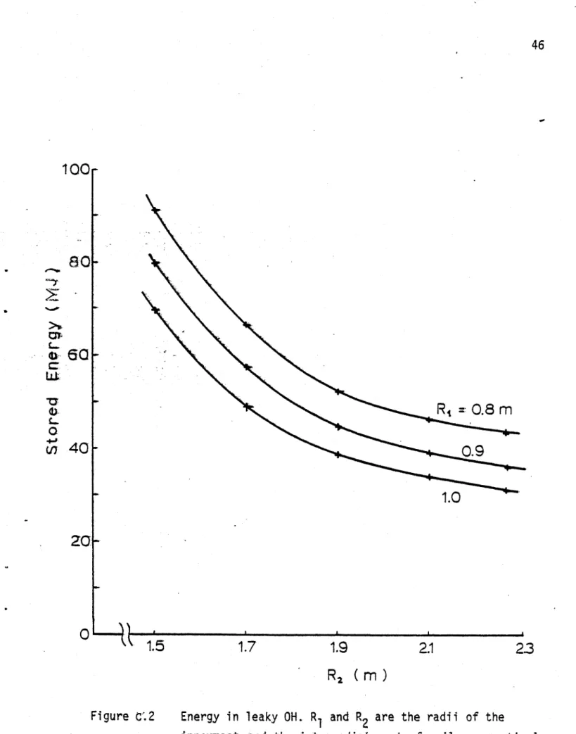
Figures C.2, C.3 and C.4 show a parametric study of the leaky OH system. The energy in the system needed to provide a fixed flux (3 V s) to the plasma is shown in Figure C.2 as a function of the radial position of the intermediate set of coils (there are three sets of coils). The different curves are for different positions of the innermost set of coils. The maximum field of the
leaky OH. field at the midplane for 1.8 < R < 2.6 m is shown in Figure C.3 as a function of the
same variables as Figure C.2 . As the position of the innermost set of coils is moved further out, the
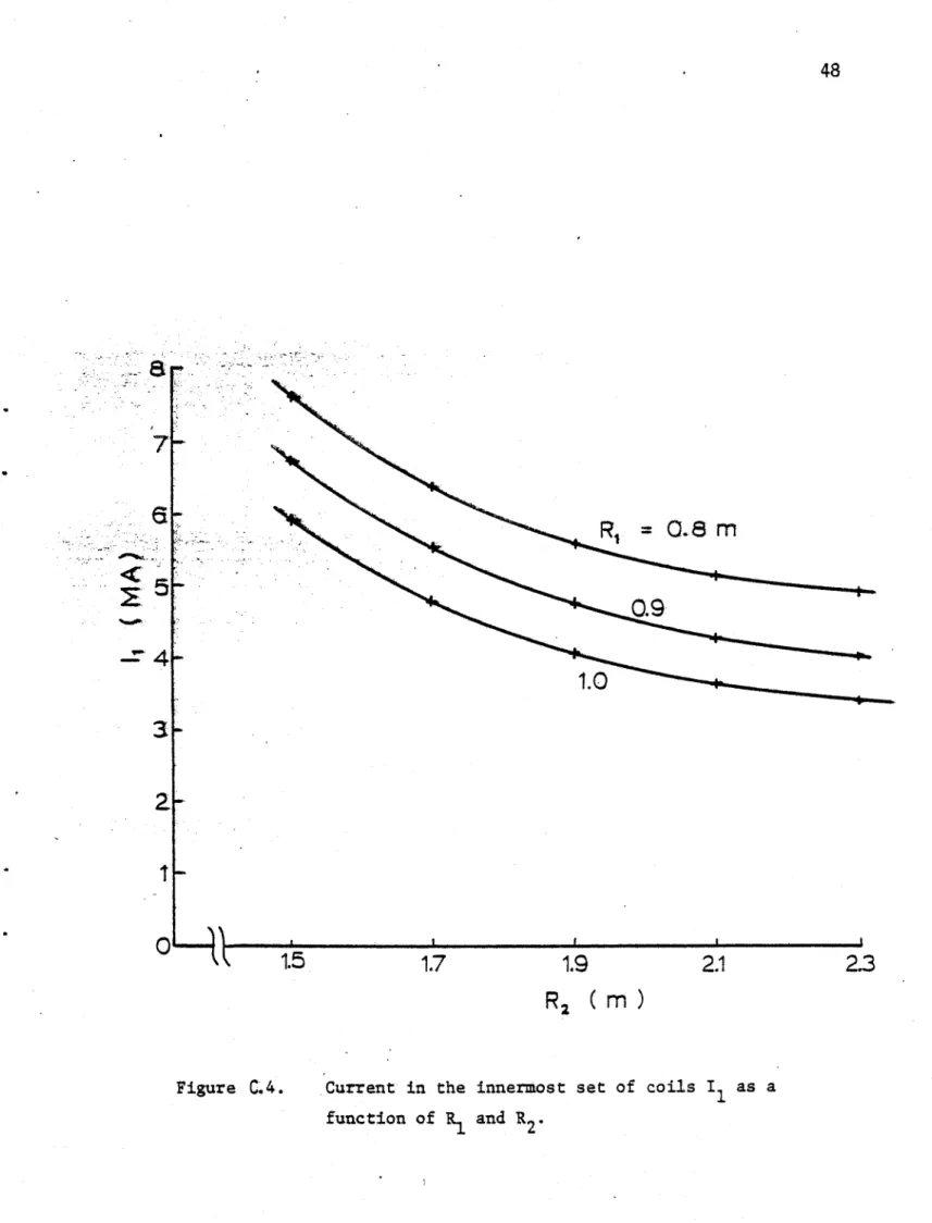
residual field in the region of the initial plasma increases significantly. The current in the innermost set of coils is shown in Figure C.4 . The current in this set of coils has been minimized subject to
having a low residual field. As the radius of the first set of coils increases, the current in this set of coils decreases. However, the residual field in the initial plasma region increases.
The major radius of the first set of coils has been chosen ~ 1. m. Parameters for a complete set of coils are shown in Table C.2 . The field of the leaky OH field is shown in Figure
C.5 for these parameters. The flux contribution to the initial plasma under these circumstances is 3
43 Table C.1 Central OH Peak field (T) forward reverse
At end of flat top Inductance at 105 A
Maximum stored energy (Md)
Maximum resistive dissipation (MW) Maximum copper stress (Pa)
Temp. after 17 sec. flat top (OK) Filling factor of central coil Weight (central coil)(10 3 Kg).
Central coil - length (m)
outer radius (m) Harmonic coils Current (MA) A 2.0 B -0.08 C 0.33 R (m) 0.7 1.3 2.2 20 17 14.2 9.5 x 10⁻³ 50 18.0 2.1 x 10⁸ 200 0.8 4.5 1.00 .33 z (m) 1.4 1.5 1.5
44 Table C.2 Leaky OH Parameters Coil Radius (m) 1.0 1.7 2.9
Coil Currents (MA)
12 13
Flux Initial Plasma (V.s)
Peak Stored Energy (MJ)
Peak Power Dissipation (MW)
Peak Stresses (MPa)
4.8 -1 .1 0.2 3 50 30 R 1 290
45 0L 0 in) 0 ILO
0
04lC~ r-0 u- 0 f4 r-4 '-4 4$ ILO 0 IL) 0 L V- V- 04j(.L)
Plaij
JDj;ua:)
46
1OOr
1.9
R2 (m)
Figure C.2 Energy in leaky OH. R and R are the radii of the
innermost and the intermediate- set of coils respectively.
80
Go
C LL~'I)
L0
.0-I40
2oF
R, =0.8 m
0.9
1.0
0
1.7
2.1
23
k1.5
47 80
70.m
6 0 -0.8 ~40 a30
20
10
011.5
1.7
1.9
2.1
2.3
R7 (M)Figure C.3 Peak residual field on midplane due to leaky OH as a function of R and R
R
m
0.91.0
7
6
3
0
Figure C.4. Current in the innermost set of coils I as a
function of R- and R2'
48
1.9
R
2 (iM))
49 44 (U U 4- 4)-.- C-0-0 1-. 0L 4-J ~1Page 50
Appendix D. Toroidal Field Coil
In Figure D.l the stored energy in the TF coil is shown as a function of the magnetic field on axis of the compressed plasma for Mlbeta - Mlbeams - I with K0 - 1.5, and OTF - 2.9 108 Pa. As the field is reduced, the stored energy decreases fast with decreasing field for Bf > 10 T and slowly thereafter.
The TF coils are made out of copper plates reinforced by stainless steel plates. In this way,
average stresses between the' copper and the steel of the order of 3.6 10 Pa in the inboard of the TF coil might be tolerated . However, the stresses that result in KO - 1.5 are below the yield
stress of hardened copper. The height of the plates is determined so that the bending stresses of the
TF coil are within the elastic limit for copper. The bending stresses in the copper are - 2.9 108 Pa
if the height of the plates is 2.4 m. This is consistent with the positions of the EF and leaky OH
coils.
' The pulse length is deterhmined by the maximum energy available in the TF power supply, subject to the constraint that the maximum temperature rise in the Tp coil be less than ~ 4000K.
The TF magnet is "inertially cooled", that is, no cooling during the pulse. The power and energy
required are shown in Figure D.2 and D.3 . The different curves are for the cases in Tables I and
II, for Mlbeta - Mlbeams - I and K0 - I and K0 - 1.5 . The end of the pulse in these figures
occurs when the peak temperature in the TF coil is 400'K. The calculations for Figures D.2 and
D.3 include 70 MW of neutrons coming from an ignited plasma. The flat top is ~ 20 s long, that is,
~ 30r,. The temperature distribution alomg the TF coil is shown in Figure D.4 for the case when
K0 - I . Approximately 29,000 liters of liquid nitrogen are evaporated in order to recool the
magnet after a 20 s ignited pulse. The parameters of the TF magnet are shown in Table V.
The absence of neutron shielding between the plasma and the TF coils places stringent
Page 51
been used to determine the neutron flux in the TF region. The inferred life expentancies of organic and inorganic insulators are shown in Table D.1 . It is possible to increase the life expentancy of the insulators by providing some shielding. This can be done without having to increase the TF coil bore by receding the insulation away from the plasma. The compressive stresses are increased by this method because the contact area between adjacent plates has been reduced. This self-shield can be ~ 0.15 m thick without perturbing the TF magnet. The neutron flux at the insulator is not decreased significantly but the energy spectra is softened.
The compression stresses in the insulator due to the inward forces in the TF magnet are
8. 107 Pa. Because of the large vertical forces in the trunk of the TF magnet, the stainless
steel-copper-insulation composite will be strained by ~ 0.3., resulting in stresses beyond the tensile stress of ceramics. The possibility of using anodized aluminum plates with or without synergistic coatings 20 is being considered as a candidate for the insulation; tests are being considered to evaluate its behavior under large strain and neutron fluences.
The possibility of using inorganically bonded mica is also being considered. Mica would be crushed by the large compressive force, but it is not expected that there will be room for the mica to shift and provide a conducting path. Tests are in progress to determine the possibility of using this insulator.
52
Table D.1
Lifetime Expectancy of Insulation t
Organic
Polyester (burn-s)
Reinforced Epoxy (burn-s) Reinforced Polyimide (burn-s) Inorganic Mica (burn-s) Alumina (burn-s) 500 5,000 5,000 500,000 500,000
t Radiation limits taken from R.D. Hay and E.J. Rapperport, "Review of Electrical Insulators in Superconducting Magnets
53
(9
1.0
LaLU
0.9
La 0 LaS0.7
(/,0.6
8
9
10
11
12
13
14
B
(T)
Figure D.l Stored Magnetic energy in the toroidal coil as a
function of magnetic field on axis for MIbeta = MI beams and K = 1.5
54 16
Cr
K=1.5
1.0
15
Time (s)
Figure O'.2 Power from the TF supply for MIbeams MI beta
and K = 1, K aL.5.
120
a
0 0~401
F' 05
10
20
25
30
35
I
55 0 LO) 010 -ItI
o
o
00 %--:, 0(
rS
)
ABJQU3
0 0 Cot 56 - I 0 0 00, 1q, 0