HAL Id: hal-01881384
https://hal.uca.fr/hal-01881384
Submitted on 25 Sep 2018
HAL is a multi-disciplinary open access
archive for the deposit and dissemination of
sci-entific research documents, whether they are
pub-lished or not. The documents may come from
teaching and research institutions in France or
abroad, or from public or private research centers.
L’archive ouverte pluridisciplinaire HAL, est
destinée au dépôt et à la diffusion de documents
scientifiques de niveau recherche, publiés ou non,
émanant des établissements d’enseignement et de
recherche français ou étrangers, des laboratoires
publics ou privés.
Decoding Superposed LoRa Signals
Nancy El Rachkidy, Alexandre Guitton, Megumi Kaneko
To cite this version:
Nancy El Rachkidy, Alexandre Guitton, Megumi Kaneko. Decoding Superposed LoRa Signals. IEEE
Local Computer Networks (LCN), Oct 2018, CHICAGO, United States. �hal-01881384�
Decoding Superposed LoRa Signals
Nancy El Rachkidy
(1), Alexandre Guitton
(1), Megumi Kaneko
(2)(1) Universit´e Clermont Auvergne, CNRS, LIMOS, F-63000 Clermont-Ferrand, France (2) National Institute of Informatics, Hitotsubashi, 2-1-2, Chiyoda-ku, 101-8430 Tokyo, Japan
Emails: nancy.el [email protected], [email protected], [email protected]
Abstract—Long-range low-power wireless communications, such as LoRa, are used in many IoT and environmental mon-itoring applications. They typically increase the communication range to several kilometers, at the cost of reducing the bitrate to a few bits per seconds. Collisions further reduce the perfor-mance of these communications. In this paper, we propose two algorithms to decode colliding signals: one algorithm requires the transmitters to be slightly desynchronized, and the other requires the transmitters to be synchronized. To do so, we use the timing information to match the correct symbols to the correct transmitters. We show that our algorithms are able to significantly improve the overall throughput of LoRa.
Index Terms—LoRa, LoRaWAN, LPWAN, Interference can-cellation, synchronized signals, desynchronized signals.
I. INTRODUCTION
Long-range low-power communication technologies such as LoRa [1], Sigfox [2], and Ingenu [3], are becoming widely used in Low-Power Wide Area Networks (LPWANs). These technologies are suitable to cover large zones and are thus becoming attractive technologies for Internet of Things (IoT) and monitoring applications [4], [5], [6].
LoRa [1] is a recent physical layer for LPWANs, which extends the communication range by reducing the throughput. LoRaWAN [7] is a simple MAC protocol based on LoRa, which allows end-devices (ED) to communicate with a small duty-cycle (1%) to a network server through gateways. Thus, EDs can save energy, and the network lifetime is increased.
The main issue in LoRa and LoRaWAN is the limited throughput: the indicative physical bitrate varies between 250 and 11000 bps [8]. Moreover, when two EDs transmit simultaneously using the same parameters, a collision occurs and none of the signals are decoded by LoRa. Thus, both EDs have to retransmit, which further reduces the throughput.
In this paper, we show that it is possible to retrieve the frames from superposed signals. For the case where super-posed signals are slightly desynchronized, we propose a linear algorithm based on timing information that attempts to decode all frames. This algorithm always succeeds when there are two signals. We prove that for three or more signals, it is not always possible to decode each signal. Next, for the case where superposed signals are completely synchronized, we propose a simple algorithm requiring only one retransmission to deduce the other colliding frame. To the best of our knowledge, this is the first work on LoRa interference cancellation.
The remainder of this paper is as follows. Section II describes the modulation of LoRa. Section III describes our
two cases (slightly desynchronized and completely synchro-nized), and presents our two algorithms. Section IV gives our simulation results. Finally, Section V concludes the paper.
II. STATE OF THE ART
In the following, we first describe the MAC protocol Lo-RaWAN, and then the physical layer LoRa. Note that our paper proposes an improvement to LoRa, which can be used to improve the performance of any MAC protocol based on LoRa (including LoRaWAN).
A. LoRaWAN
LoRaWAN (in version 1.0 [9] or in version 1.1 [7]) is a MAC protocol based on LoRa. Three classes are defined, depending on the communication paradigm: Class A is for low-power uplink communications, Class B is for delay-guaranteed downlink communications, and Class C is for EDs without energy constraints. In Class A, the only mandatory class of LoRaWAN, an ED can transmit at any time. It chooses a channel randomly, sends the frame, and waits for an acknowledgment during two successive receive windows. After its transmission, the ED is forbidden to transmit for a delay equal to 99 times the duration of the frame transmission. In this way, the transmission time of EDs does not exceed 1%. LoRaWAN adapts the bitrate to the quality of links by implementing a trade-off between the signal robustness and the bitrate, through the use of the Spreading Factor (SF) of the signal: when an ED experiences a low signal quality, it increases its SF, which results into lower bitrate, but better decoding capabilities of the signal. This modification is con-trolled by the datarate (DR) of LoRaWAN, which is a value ranging from DR0 (large SF, small bitrate) to DR6 (small SF, large bitrate).
European regional settings of LoRaWAN [8] define most LoRa parameters. The bandwidth of channels,BW , is equal to 125 kHz for DR0 to DR5, and 250 kHz for DR6. The SF varies from 12 down to 7 for DR0 to DR5, and is equal to 7 for DR6. The preamble length is equal to 8 symbols. The physical bitrate varies between 250 bps for DR0, to 11000 bps for DR6. The maximum MAC payload of a frame varies between 59 bytes for DR0 and 230 bytes for DR6.
B. LoRa
LoRa is a physical layer technology for LPWAN, based on a Chirp-Spread Spectrum (CSS) modulation. In this modulation, each LoRa chirp consists of a linear frequency sweep. The
duration of the sweep is called symbol duration (SD), and depends on the value of SF. The sweep is performed over a frequency range of size BW . Chirps are divided into up-chirps, where the frequency sweep is increasing, and down-chirps, where the frequency sweep is decreasing.
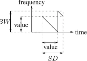
Each chirp can encode2SF
symbol values. To do this, LoRa shifts the sweep by the symbol value, as shown on Fig. 1 for a down-chirp. The receiver is able to detect the sharp edge in the instantaneous frequency trajectory [10]. The symbol value is equal to the shift in the frequency at the beginning of the symbol. It is also proportional to the time between the beginning of the symbol and the sharp frequency edge. For up-chirps, it is proportional to the remaining time between the sharp frequency edge and the end of the symbol.
frequency BW value value SD time
Figure 1. Example of a single LoRa down-chirp. Computing the symbol value requires identifying the sharp frequency edge.
To decode the value of a symbol, the receiver needs to know the frontier of the symbol. Thus, LoRa introduces a preamble of a few symbols (typically, eight). In uplink communications, the preamble consists of up-chirps and the data consists of down-chirps. In downlink communications, the preamble consists of down-chirps and the data consists of up-chirps.
Figure 2 shows an example of an uplink communication with a short preamble (three symbols) and a few data symbols (four symbols). We chose SF = 2 for the sake of simplicity, leading to2SF
= 4 possible values per symbol. Let us assume that a desynchronized node starts receiving the preamble, not necessarily at the exact beginning of the preamble. The node detects a sharp frequency edge, which indicates the frontier of a symbol. From this information, the receiver can synchronize itself according to the transmitter. The end of the preamble is detected by the inversion of the chirps. In this example, the data symbols are 3, 0, 2, 2.
sender
receiver
preamble 3 0 2 2
desynchronization information
Figure 2. Example of a LoRa uplink frame, with a short preamble and four symbols of data, with SF = 2. The receiver synchronizes itself with the sender during the preamble.
III. CANCELLATION OFLORA SIGNALS
LoRa gateways are able to decode superposed LoRa signals as long as they are sent on different SFs. Notice however that some researchers have shown that signals on different SFs are not completely orthogonal [11], [12].
When several signals are received on the same channel and with the same SF, a difference of received power might cause the strongest signal to be captured [10], [13]. When several signals have a similar receive power, a collision occurs and all signals are considered lost.
In this paper, we focus on decoding superposed LoRa signals of similar receive power, on the same channel, with the same SF. To do so, we show that we can use timing information to match the correct symbols to the correct ED.
In Subsection III-A, we describe our assumptions. In Sub-section III-B, we provide our main algorithm, and we describe how it can decode two signals that are slightly desynchronized. In Subsection III-C, we extend the discussion for the case of three signals (or more) that are slightly desynchronized. Finally, in Subsection III-D, we apply a similar algorithm on a different case, where signals are completely synchronized.
Note that our algorithms cannot be applied directly on LoRaWAN, as most communications in LoRaWAN are not synchronized. However, our algorithms could enable the de-sign of a novel synchronized MAC layer based on LoRa, tailored to the star like topology of LoRaWAN, to reach better performances than the basic LoRaWAN.
A. Assumptions
We assume that there are no non-linearity effects between down-chirps (respectively up-chirps). In other words, if two down-chirps (resp. up-chirps) c1 and c2 overlap at a given
timet at the receiver side, the two observed frequencies are the frequency of c1 (at time t) and the frequency of c2 (at
time t). Without additional information, it is not possible to identify the correct frequency of each transmitter. We assume that when an up-chirp is superposed with a down-chirp, it is not possible to detect any of the frequencies.
We also assume that it is possible for the hardware of the receiver to detect all frequencies of overlapping down-chirps (resp. up-down-chirps) within δ time-units. In the following examples, we will useδ = SD/4 unless stated otherwise1
. We assume that when several frequencies overlap at a given time, only one frequency is detected by the receiver. For instance, if there are three nodes transmitting at a given time, but only two frequencies f1 and f2 are detected, we
assume that it is not possible to know whether two nodes were transmitting with f1 and one withf2, or one node was
transmitting withf1 and two withf2.
1Please note that on real LoRa hardware, the decoding of signals is not
carried out by directly detecting the sharp frequency edges, but instead by computing a fast Fourier transform and detecting the peak in the frequency domain [10]. With our proposition, this translates into either detecting the two sharp frequency edges in the time domain, or the two peaks in the frequency domain.
We also assume some properties on the frames: all nodes transmit with the same preamble duration, the frame length is included at the beginning of the frame, and there is at least one symbol change during the whole frame (that is, a data payload does not consist of a sequence of identical symbols). Finally, in the following, we consider two cases: the case where nodes are slightly desynchronized, and the case where nodes are fully synchronized. In the case where nodes are slightly desynchronized, we assume that all nodes start and finish their transmission within SD − δ time units, and that any two nodes start and finish their transmission with a delay ofδ time units or more. We do not consider clock drift. In the following examples, if there are three transmitting nodes, we consider that noden1starts at timet0, noden2at timet0+ δ,
and noden3 at timet0+ 2δ.
B. Case of two slightly desynchronized signals
In this subsection, we consider the superposition of two signals from two transmitters that are slightly desynchronized (by at leastδ time units, and at most SD − δ time units).
Figure 3 shows an example of the reception of two slightly desynchronized signals. The preamble length is two symbols, andSF = 2. The figure shows the signal of the first transmitter n1starting att0, the signal of the second transmittern2starting
att0+δ, and the superposed signal at the receiver. Note that the
data transmitted byn1is(1, 1, 3, 2, 2), and the data transmitted
by n2 is(3, 0, 2, 3, 1). We will first explain our algorithm on
this example, and then proceed with a more formal description.
n1 n2 receiver t0 t1 t2 t3 t4 t5 t6 t7 t8 t9 t10 t11 t12 0 1 1 1 2 2 2 3 3 3 δ
Figure 3. Superposition of two slightly desynchronized signals.
Example of Preamble detection and data decoding
In this paragraph, we give an example in order to explain how the receiver, using our proposition, can detect preambles and decode data sent by two transmitters.
Preamble detection:During[t0; t0+ δ], the receiver detects
the preamble of n1. During [t0+ δ; t0+ 2δ], the receiver is
able to detect that two slightly desynchronized signals are transmitted, and is able to deduce the symbol frontiers of both transmitters. At frontier t1, or more precisely, during
[t1; t1+ δ], the receiver is not able to detect the superposition
of preambles anymore (mixed up and down chirps). Thus, it knows that the transmission of the first data symbol of n1
has started. This symbol is currently undecodable due to the overlapping of an up-chirp with a down-chirp.
Data decoding:We define the sequence of decoded data for n1 byd1 and the sequence of decoded data forn2 byd2. At
frontiert2, the receiver stores the current frequencies, which
correspond toFlim
−(t2) = {0, 3}. At frontier t3, the receiver
computes Flim+(t3) by updating the previous frequencies
Flim−(t2) = {0, 3}, and obtains Flim+(t3) = {0, 1} (each
frequency is reduced by 3 since 3δ time units have passed since t2, as δ = SD/4). It detects the current frequencies
Flim
−(t3) = {0, 1}. There is no change in the frequencies
(Flim+(t3) = Flim−(t3)), since the beginning of the data
ofn1 starts with the repeated symbol 1. Thus, the algorithm
leaves ∗ for the first symbol of n1 (to be decoded later), so
d1 = (∗, 1). At frontier t4, the receiver computes Flim+(t4)
by updating the previous frequencies Flim
−(t3) = {0, 1},
and obtains Flim+(t4) = {0, 3} (since δ time units have
passed). It detects the current frequencies Flim
−(t4), and
obtains Flim
−(t4) = {0}, which is equivalent to {0, 0}.
Thus, one frequency changed from 3 to 0, which is that of n2, since it is a frontier of n2, hence, d2 = (3, 0). Thus,
the current symbol of n1 corresponds to frequency 0 too
(which is translated into 1 at the beginning of the symbol frontier of n1, which was t3). At frontier t5, the receiver
computes Flim+(t5) by updating the previous frequencies
Flim−(t4) = {0, 0}, and obtains Flim+(t5) = {1, 1}. It detects
the current frequenciesFlim
−(t5) = {1, 3}. The frequency of
n1 changed from 1 to 3, henced1= (∗, 1, 3). So, the current
symbol ofn2 corresponds to frequency 1 (which is translated
to 0 at the beginning of the symbol frontier of n2, which is
t4). The algorithm continues until t12, where no frequency
is received. Thus, the algorithm knows that all nodes have stopped their transmissions. The algorithm removes the last predicted symbol of n1 (indeed, at t11, it considered that
n1 was transmitting a symbol with the same frequency as
the frequency of n2). At this step, the decoded frames are
d1 = (∗, 1, 3, 2, 2) for n1 and d2 = (3, 0, 2, 3, 1) for n2.
Then, the algorithm replaces all special values ∗ with the first known value of the frame. The algorithm uses the frame length present in each frame to truncate the frames to their correct length. Finally, the algorithm outputs are(1, 1, 3, 2, 2) and(3, 0, 2, 3, 1), as expected.
Generalization of Preamble detection and data decoding
In this paragraph, we generalize the example given above and we formulate our proposition in Algorithm 1.
Preamble detection: The superposition of preambles will result in the superposition of up-chirp symbols, except for the end of the last preamble. Thus, the receiver will detect two sharp frequency edges for most preamble symbols. Each of this sharp edge will allow the receiver to know the symbol frontier of a transmitter. The beginning of the first data symbol of the first node is not decodable, as it corresponds to a down-chirp superposed with the up-down-chirp of the end of the preamble of the second node.
Data decoding: From the first data symbol of the second node, only down-chirps are superposed, and thus it is possible
to detect all sharp edges. The difficulty relies in correlating each frequency with the symbols of each node. To do so, we use the following property: sharp edges can occur only at the beginning of a symbol, when the symbol changes, or once during a symbol. When the sharp edge occurs during a symbol, it can be predicted if the symbol value is known.
Algorithm 1 describes our proposed algorithm. It starts after the superposed preambles have been received, and thus considers that the symbol frontier of each transmitter is known. The algorithm considers the frontiers of all data symbols sequentially, apart from the first frontier of the first node which cannot be decoded. At each frontier, the receiver updates the previous frequencies (since frequencies change over time in LoRa chirps, and time has passed since the detection of the previous frequencies). Then, the receiver compares these (updated) previous frequencies with the current frequencies2. The following two cases are the only possible cases.
Case 1: One frequency has changed. This can only happen when a new symbol starts, which can only occur at the symbol frontier. Since the receiver knows if the current frontier is for the first or the second transmitter, it knows the new symbol for the current node (based on the new frequency), the previous symbol for the current node (based on the frequency that has changed), and the current symbol for the other node (based on the frequency that did not change).
Case 2: No frequency has changed. This can only happen when the new symbol is equal to the previous symbol (this was the case on Fig. 3 at timest3andt9). If the receiver knows
the previous symbol of the current node (time t9 of Fig. 3),
the new symbol can be deduced. Note that at the beginning of the algorithm, however, the first symbol value cannot be deduced when it is repeated (time t3 of Fig. 3). In this case,
the algorithm leaves a special value (denoted by ∗ here). As soon as one symbol changes, the receiver is able to deduce the values of all these repeated symbols. This is why we assumed at least one symbol change per frame.
The time complexity of our algorithm is linear with the number of symbols of the longest frame. Most of the symbols are decoded on the fly,δ time units after the beginning of the symbol, except for the symbols repeated initially (see the last loop of the algorithm). The space complexity of our algorithm isO(1), since the storage requirement is limited to the value of the first non-special symbol for each node. Thus, the algorithm is optimal in time and space, for two nodes3.
C. Case of three slightly desynchronized signals
Note that with our hypotheses, decoding three or more signals is not always possible. For instance, Fig. 4 shows two sets of different signals that produce the same superposition of frequencies, and thus cannot be decoded.
2In practice, it may take up to δ time units to obtain the current frequencies,
so the receiver might have to update the current frequencies based on the detection time.
3As we will see in Subsection III-C, our algorithm is not able to decode
all frames for three nodes or more, so it cannot be considered optimal in this case.
Algorithm 1: Decoding of two slightly desynchronized superposed LoRa signals.
for each frontierti of a data chirp do
compute currentSymbol and currentNode if currentSymbol=0 and currentNode=1 then
skip (frequencies cannot be detected) else
Flim
−(ti) ←detect current frequencies
if currentSymbol=0 and currentNode=2 then skip (Flim−(ti) is already computed)
else
computeFlim+(ti) by updating Flim−(ti−1)
changedF ← Flim−(ti) − Flim+(ti)
ifchangedF = ∅ then
the new symbol insymb[currentNode] is equal to the previous (or∗)
else
the previous symb. insymb[currentNode] is equal to the value ofchangedF the new symbol insymb[currentNode] is
equal to the value of Flim+(ti) − Flim−(ti)
for each noden do
replace insymb[n] all the leading ∗ values to the first defined value
truncate the frame according to its length
n1 n2 n3 receiv. 0 0 0 0 0 0 0 0 0 0 1 1 1 1 1 1 2 2
Figure 4. When three nodes that are slightly desynchronized transmit frames, it is not always possible to decode them: these two sets of frames produce the same superposition of frequencies.
Our algorithm is able to decode many cases of slightly desynchronized signals for n transmitters, when n ≥ 3. It only fails to do so when the number of received frequencies is within [2; n − 1] (which never occurs when n = 2). In this case, even if the algorithm knows that the frequency of the current node has changed, it cannot determine what is the new value, as it hasn − 1 > 1 possibilities. It can still deduce the value of the previous symbol for this node. At the next frontier for this node, though, the value of this symbol might be deduced, depending on the number of other frequencies.
D. Case of two synchronized signals
We now consider the case of two synchronized signals. When the two transmitters are completely synchronized, it can be noticed that (at most) two values for each symbol duration are obtained, one for each transmitter. With our assumptions, though, it is not possible to match each value to the correct transmitter. The uncertainty of two values for each symbol might seem large, but it is quite small compared to the fact that each symbol carries in factSF bits of data.
Thus, we apply a similar algorithm as the case of slightly desynchronized signals for this case. When two synchronized frames collide, the algorithm stores the two possible values for each symbol. Then, the receiver requests one of the senders to retransmit its frame. Upon receiving this new frame, the receiver compares this frame with the collided frames received previously, and then it can match the symbols of the second frame, without requiring a retransmission. Overall, only one sender had to retransmit its frame.
For example, let us assume that (0, 1, 2, 3) and (3, 1, 0, 0) are sent simultaneously. The receiver is not able to decode any of these two frames, but it can deduce that the first symbols were 0 and 3, the second symbols were both 1, the third symbols were 0 and 2, and the fourth symbols were 0 and 3. The matching between the symbols and the corresponding sender has to be determined, for each symbol. Thus, the receiver requests the retransmission of one frame, and obtains (0, 1, 2, 3). At this time, the receiver deduces that the first symbol of the second frame was 3, the third symbol was 0 and the fourth symbol was 0.
IV. NUMERICAL RESULTS
In this section, we evaluate, by simulation, the performance of our algorithms in terms of percentage of successful decod-ing of colliddecod-ing signals and throughput. We consider the two cases independently.
A. Parameter Settings
Simulations are carried out using our own simulator de-veloped in Perl. We model a network with a single gateway, a single network server, and one hundred EDs. We assume that all the EDs transmit on the same channel with the same SF, and that their signals are received at roughly the same power levels at the gateway, i.e., no capture conditions. We assume that time is divided into slots, and each ED has a probabilityp to transmit a frame during a slot, with p ≤ 0.01
in order to be consistent with the duty-cycle of 1%. For our algorithms, transmissions on the same slot are considered to be slightly desynchronized (in Subsection IV-B) or completely synchronized (in Subsection IV-C). We choose two values for SF:SF 7 (which is the smallest SF in LoRaWAN) and SF 12 (which is the largest SF in LoRaWAN). The frame length is set to 50 bytes. We did not force frames to have at least one symbol change. However, the probability that a frame is generated with the same repeated symbol is very small, and we did not observe it during our simulations. Simulation results are obtained by averaging over ten thousand samples.
B. Case of slightly desynchronized signals
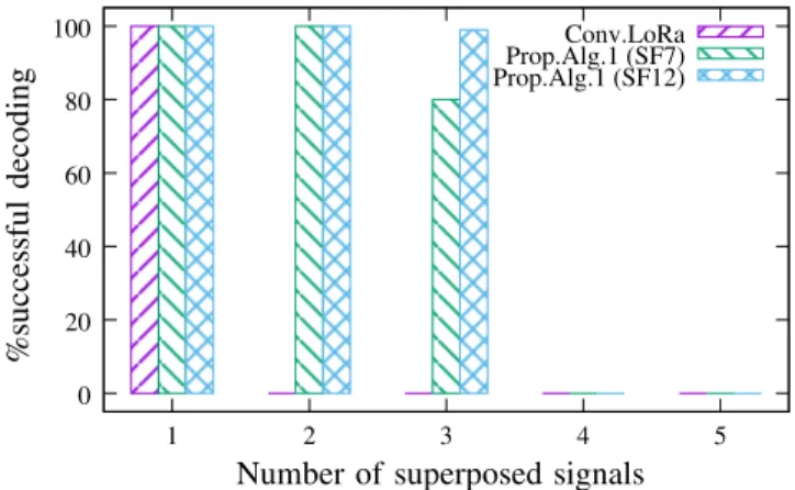
Figure 5 shows the percentage of successful decoding of colliding signals, as a function of the number of colliding signals, in the case where signals are slightly desynchronized. When there are two or more colliding signals, LoRa is not able to decode any signal. When there are exactly two colliding signals, our algorithm is always able to decode both of them. When there are three or more colliding signals, our algorithm is not able to decode some signals: the proportion of signals that can be decoded depends onSF and on the frame length. Indeed, when SF is large, the number of possible values for each symbol is large, and the probability that several transmitters use the same frequency is low. ForSF = 7 and n = 3 colliding frames, our algorithm is able to decode about 80% of the frames. This number drops rapidly as the number of transmitters increases. Conv.LoRa Prop.Alg.1 (SF7) Prop.Alg.1 (SF12) 0 20 40 60 80 100 1 2 3 4 5 % su cc es sf u l d ec o d in g
Number of superposed signals
Figure 5. When the signals are slightly desynchronized, our algorithm is able to successfully decode some cases of colliding signals.
Figure 6 shows the percentage of successful decoding of colliding signals, as a function of the SF, for n = 2 and n = 3 superposed signals. We notice that LoRa is not able to decode colliding signals for any SF. This is due to the fact that in LoRa, a gateway cannot receive more than one signal on the same channel and with the same SF. However, we can see that our algorithm can decode both signals when n = 2. When n = 3, the performance of our algorithm varies significantly with SF. This is due to the fact that with a large SF, the probability to detect a single frequency decreases. Thus, the gateway increases its chances to receive a number of frequencies equal to the number of symbols to decode.
Thus, compared to LoRa, our algorithm achieves a gain of 100% when the gateway received two colliding signals and a gain between 18% and 99% when the gateway received three colliding signals. Conv.LoRa Prop.Alg.1 (n=2) Prop.Alg.1 (n=3) 0 20 40 60 80 100 4 6 8 10 12 % S u cc es sf u l d ec o d in g SF
Figure 6. Our algorithm outperforms LoRa when a gateway receives n= 2 or n= 3 colliding signals, with the same SF and on the same channel.
Figure 7 shows the throughput as a function of the duty-cycle. In this scenario, we consider a network of one hundred EDs with a duty-cycle less or equal to 1%. We compute throughput for LoRa and for our algorithm for two values of SF: SF7 and SF12. We notice that the throughput increases when the duty-cycle increases, since each ED sends more frames. Our algorithm enables to achieve a much higher throughput than LoRa, with a gain of up to 60% for a duty-cycle of 1%. This shows that our algorithm provides remarkable throughput gains, even at the system level.
LoRa [1] (SF7) Algo 1 (SF7) LoRa [1] (SF12) Algo 1 (SF12) 0 5 10 15 20 25 30 35 40 0.2 0.3 0.4 0.5 0.6 0.7 0.8 0.9 1 T h ro u g h p u t (b it s/ s)
Duty-cycle (in percentage)
Figure 7. Colliding signals negatively impact the throughput in LoRa. However, our algorithm is able to increase the throughput up to 60% when the duty-cycle is equal to 1% and the network is of 100 EDs.
C. Case of synchronized signals
Figure 8 shows the percentage of successful decoding of colliding signals, as a function of the number of colliding signals, in the case where signals are synchronized. Since LoRa is unable to decode any signal when there are several EDs transmitting on the same channel and with the same SF, the percentage of successfully decoded signals is zero for two
and more colliding signals. With our algorithm, when there are exactly two simultaneous transmissions, one of them can be decoded provided that one node retransmits its whole frame. Thus, forn = 2 colliding signals, our algorithm decodes 50% of the frames, accounting for the retransmission time.
00
00
11
11
00
00
00
00
00
00
00
00
00
11
11
11
11
11
11
11
11
11
00
11
0
1
0
1
0
1
00
11
0
0
0
0
0
0
0
0
0
1
1
1
1
1
1
1
1
1
00
00
00
00
00
00
11
11
11
11
11
11
00
11
00
11
0
1
Conv.LoRa Prop.Alg.2 0 20 40 60 80 100 1 2 3 4 5 % S u cc es sf u l d ec o d in gNumber of colliding signals
Figure 8. When the signals are synchronized, our algorithm is able to decode one frame per collision of two frames, provided that the other one is retransmitted.
Figure 9 shows the throughput as a function of the duty-cycle. The throughput computed by Conv.LoRa shows the same performance as the one computed for the desynchronized signals. However, with our second algorithm, the gateway is able to decode one frame for each collision of two frames, pro-vided that the other frame is retransmitted. Thus, our algorithm computes a gain of up to 25% compared to LoRa. Compared to the case where transmissions are slightly desynchronized, we observe a decrease of 50% of the throughput.
LoRa [1] (SF7) Algo 2 (SF7) LoRa [1] (SF12) Algo 2 (SF12) 0 5 10 15 20 25 30 35 40 0.2 0.3 0.4 0.5 0.6 0.7 0.8 0.9 1 T h ro u g h p u t (b it s/ s)
Duty-cycle (in percentage)
Figure 9. Colliding signals negatively impact the throughput in LoRa. However, our algorithm is able to increase the throughput by up to 25% even for synchronized signals and 100 EDs.
V. CONCLUSION
Collisions in LoRa negatively impact the throughput of the network, which is already very limited by definition. In this paper, we assume that LoRa transceivers are able to detect fre-quency sweeps over a duration smaller than a LoRa chirp. We propose two novel collision resolution algorithms that enable to decode some cases of collisions in LoRa by exploiting the
specific properties of this physical layer. Our first algorithm focuses on the case where nodes are slightly desynchronized. The second algorithm focuses on the case where nodes are synchronized. Based on our simulation results, we observe that the first algorithm is able to significantly improve the throughput, by decoding all collisions of two signals, and many collisions of three signals. The second algorithm is also able to improve the throughput, but by decoding only one signal when two signals are colliding. These results promote the investigations of a new MAC layer based on LoRa, leveraging on the proposed collision resolution algorithms and thereby outperforming LoRaWAN.
REFERENCES
[1] Semtech Corporation, “AN1200.22 LoRa Modulation Basics,” Semtech, Application note Revision 2, 2015, accessed 2018-01-29. [Online]. Available: http://www.semtech.com/uploads/documents/an1200.22.pdf [2] Sigfox, http//www.sigfox.com.
[3] Ingenu, http//www.ingenu.com.
[4] M. Centenaro, L. Vangelista, A. Zanella, and M. Zorzi, “Long-range communications in unlicensed bands: the rising stars in the IoT and smart city scenarios,” IEEE Wireless Communications, 2016.
[5] K. E. Nolan, W. Guibene, and M. Y. Kelly, “An evaluation of low power wide area network technologies for the internet of things,” in
Inter-national Wireless Communications and Mobile Computing Conference (IWCMC), pp. 439–444.
[6] J. Pet¨aj¨aj¨arvi, K. Mikhaylov, R. Yasmin, M. H¨am¨al¨ainen, and J. Iinatti, “Evaluation of LoRa LPWAN technology for indoor remote health and wellbeing monitoring,” International Journal of Wireless Information
Networks, vol. 24, no. 2, pp. 153–165, 2017.
[7] LoRa Alliance Technical Committee, “LoRaWAN 1.1 Specification,” LoRa Alliance, Standard V1.1, 2017.
[8] ——, “LoRaWAN 1.1 Regional Parameters,” Standard V1.1, Revision A, 2017.
[9] N. Sornin, M. Luis, T. Eirich, T. Kramp, and O. Hersent, “LoRaWAN Specification,” LoRa Alliance, Standard V1.0, 2015.
[10] C. Goursaud and J.-M. Gorce, “Dedicated networks for IoT: PHY / MAC state of the art and challenges,” EAI endorsed Transactions on
Internet of Things, 2015.
[11] D. Croce, M. Gucciardo, I. Tinnirello, D. Garlisi, and S. Mangione, “Im-pact of spreading factor imperfect orthogonality in LoRa communica-tions,” in International Tyrrhenian Workshop on Digital Communication
(TIWDC), ser. Communications in Computer and Information Science (CCIS), vol. 766, 2017, pp. 165–179.
[12] G. Zhu, C.-H. Liao, M. Suzuki, Y. Narusue, and H. Morikawa, “Evalua-tion of LoRa receiver performance under co-technology interference,” in
IEEE Consumer Communications and Networking Conference (CCNC), 2018.
[13] J. Haxhibeqiri, F. Van den Abeele, I. Moerman, and J. Hoebeke, “LoRa scalability: a simulation model based on interference measurements,”