HAL Id: hal-01976107
https://hal.laas.fr/hal-01976107
Submitted on 17 Jan 2019
HAL is a multi-disciplinary open access
archive for the deposit and dissemination of
sci-entific research documents, whether they are
pub-lished or not. The documents may come from
teaching and research institutions in France or
abroad, or from public or private research centers.
L’archive ouverte pluridisciplinaire HAL, est
destinée au dépôt et à la diffusion de documents
scientifiques de niveau recherche, publiés ou non,
émanant des établissements d’enseignement et de
recherche français ou étrangers, des laboratoires
publics ou privés.
Interleaving symbolic and geometric reasoning for a
robotic assistant
Samir Alili, Amit Kumar Pandey, Emrah Akin Sisbot, Rachid Alami
To cite this version:
Samir Alili, Amit Kumar Pandey, Emrah Akin Sisbot, Rachid Alami. Interleaving symbolic and
geometric reasoning for a robotic assistant. ICAPS Workshop on Combining Action and Motion
Planning, May 2010, Toronto, Canada. �hal-01976107�
Interleaving Symbolic and Geometric Reasoning for a Robotic Assistant
———–
(Extended Abstract)
Samir Alili, Amit Kumar Pandey, Emrah Akin Sisbot, Rachid Alami
CNRS ; LAAS ; 7 avenue du Colonel Roche, F-31077 Toulouse, France Universit´e de Toulouse ; UPS, INSA, INP, ISAE, LAAS, F-31077 Toulouse, France
Introduction
It is now well known that while symbolic task planners have been drastically improved to solve more and more complex symbolic problems the difficulty of successfully applying such planners to robotics problems still remains. Indeed, in such planners, actions such as “navigate” or “grasp” use ab-stracted applicability situations that might result in finding plans that cannot be refined at the geometrical level. This is due to the gap between the representation they are based on and the physical environment (see the pioneering paper (Lozano-Perez, Jones, and Mazer 1987)).
We have proposed in (Cambon, Gravot, and Alami 2004; Cambon, Alami, and Gravot 2009) a general framework, called AsyMov, for intricate motion, manipulation and task planning problems. This planner was based on the link between a symbolic planner running Metric FF (Hoff-mann 2003) with a sophisticated geometric planner that was able to synthesize manipulation planning problems (Alami, Sim´eon, and Laumond 1990; Sim´eon et al. 2003). The sec-ond contribution of AsyMov was the ability to csec-onduct a coordinated search of the symbolic task planner and its geo-metric counterpart.
In this paper, we extend this approach and apply it to the challenging context of human-robot cooperative manipula-tion. We propose a scheme that is still based on the coali-tion of a symbolic planner (Alili et al. 2009) and a geomet-ric planner (Pandey and Alami 2010; Sisbot, Marin Urias, and Alami 2007; Marin Urias, Sisbot, and Alami 2008) but which provides a more elaborate interaction between the two planning environments.
The overall planning system starts from a goal or a sit-uation to achieve, and builds a so-called cooperative plan which is based on planned actions for the robot and estima-tion of feasibility of acestima-tions for the human.
The task planner builds incrementally the cooperative plan, a tree task structure - thanks to a HTN refinement pro-cess - whose leaves correspond to actions to be performed by the robot or by its human partner.
We describe here below the two components, the geomet-ric and the symbolic planners, how they are invoked in a
Copyright c 2010, Association for the Advancement of Artificial Intelligence (www.aaai.org). All rights reserved.
hybrid planning scheme and finally we illustrate their inter-leaved cooperation through an example.
The Geometric Planner
The geometric reasoning and planning system considers a geometric environment (see figure 4) composed of furniture (fixed obstacles), agents (robots and humans, represented as kinematic structures with manipulation and perception abil-ities) and objects that can be manipulated by the agents.
The geometric planner is able to plan feasible motions for agents (robot or human) as well as to reason on their accessi-bilities and their visiaccessi-bilities towards other agents or towards the features in the environment.
Layers of Geometric Planner
As illustrated in figure 1, the geometric planner consists of 3 main layers:
Geometric Tools Layer: This layer consists of a set of ge-ometrical tools which provides the robot with the following geometrical analysis capabilities:
• A place in 3D space is reachable or visible from the per-spective of an agent or not by applying a set of virtual ac-tions e.g making the agent virtually to sit, to turn around, to lean forward, to standup etc.
• An object is visible or not as well as visibility % of the object from the perspective of an agent.
• The spatial relations of an object, e.g on the table, in the box, left of human etc.
Geometric Reasoning Layer: At the top of the basic layer, we have the geometrical reasoning layer, which ge-ometrically finds out a set of points for performing various basic actions, few of them are:
• Put an object for human to take. • Show an object to human. • Hide an object from human.
This layer also does various other analyses, computations and planning, few of them are:
!
!
!
!
!
!
!
!
!
!
!
!
Geometric Planner
Geometric Reasoning Geometric Validation and RefinementSet of Geometric Tools
Figure 1: Layers of Geometric Planner
• Planning a path to manipulate an object by an agent. • Computing where to place a robot for performing a
par-ticular task.
• Analyzing geometrical level of comfort of agents . Validation and Refinement Layer: At the top layer of geometric planner we have a geometric validation and re-finement interface, which communicates with external mod-ules (symbolic planner in our case) and handles external re-quests, about geometric feasibility of a particular basic task. It maintains and updates the plan, as well as contains logics for backtracking at geometric level. As shown in figure 2, in our current implementation, the symbolic planner sends a request to geometric planner with following information: • Name of the action, put, pick, move etc.
• The parameters of the action, on table, bottle, by robot, by human etc.
• The set of constraints, for example a particular object should be visible, or should be put on a particular table etc.
Types of constraints
We have three types of constraints at geometric level: • Internal constraints known to the geometric reasoning
system for performing a particular basic task.
• External/additional constraints provided by the symbolic planner for the same basic task.
• Discovered constraints by geometric planner due to fail-ure at later stages of validating another task in the se-quence.
In fact, the beauty of our whole system is, the geometric planner will already have a basic set of constraints for rea-soning to perform a particular action without need of any
!
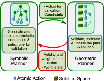
Atomic Action Solution Space! ! ! ! ! ! ! ! ! Geometric Planner Validate, maintain & update the plan
& solution spaces. ! ! ! ! ! ! ! ! ! Symbolic Planner Generate and maintain symbolic sequences & select one for validation - Validity and weight of the action - World state - Action for validation - Constraints
Figure 2: Communication between geometrical and sym-bolic planner and their roles in the overall system.
external constraint. Hence, additional constraints from sym-bolic planner will refine the solution space for better con-verging towards the final task to achieve.
Another novelty of our system is that, in case of non-availability of a solution for a particular action in the se-quence, instead of directly sending the fail message to the symbolic planner, it will first try to backtrack at geometric level to find the possible cause of failure and refine the so-lution space of a particular action. In that sense robot will have a third set of geometric constraints, which it has discov-ered due to failure during validating the sequence of actions. This third set of discovered geometric constraints together with the set of constraints already known to the robot at ge-ometric planner level and the set of additional constraints provided by the symbolic planner, will serve as the new set of constraints for avoiding failure at future steps while re-iterating for validation of the plan after backtracking.
The Symbolic Planner
HATP (Human-Aware Task Planner) is a hierarchical task planner (Alili et al. 2009) designed to synthesize plans for a robot that might have to achieve goals in an environment where other “agents” are present (essentially humans). The robot will have to produce a plan by taking into account its capacities and the current state of the environment. What makes HATP different is that it allows the robot to take into account also the state and the capacities of the other agents and even their preferences. The result of a planning is a plan with several synchronized streams, the stream of the robot as well as a set of streams that are devoted to anticipate the future potential actions of the other agents (Alili et al. 2009). Besides complying with standard constraints, HATP plans are bound to additional properties like the satisfaction of “social rules” (Alili, Alami, and Montreuil 2008).
In order to consider geometric feasibility of symbolic plans, we have adapted HATP plan search process and
ex-tended its world and task representation in order to provide a systematic link between the symbolic descriptions manip-ulated by HATP and their geometric counterpart.
The geometry enhances the symbolic reasoning by allow-ing it to use facts that depend exclusively on the geometry like “visibility” and “accessibility”, also it allows to reject plans that are feasible at symbolic level, but do not have a valid geometric refinement.
World state Task representation Plans Geometric Planner Geometric representation of entities Kinematic representation of agents Geometric computation of spatial relation Geometric representation counter part Geometric state Path Set of entities -Agent Facts - Symbolic attributs - Spatial relation between entities HTN Methods Actions - Symbolic action - Spatial action Sequence of actios Symbolic Planner
Figure 3: Links between the symbolic and the geometric representations of entities, actions and plans
World states representation
The world state is defined by the pair W s =< Ent, Spacial F acts > where
• Ent =< En1, En2, ..., Enn > is set of entities. An
en-tity is unique and it is represented by the pair Eni =<
SAtti, Sci > where SAttiis a set of symbolic attributes
and where Sciis a reference to its geometric description.
We make a difference between passive entities and active entities, called “Agents” which can perform actions and modify the state of the world.
• Spacial F acts represent the spatial relations that could exist between entities. This facts are assumed to be com-puted by the geometric planner. An example of spacial fact is the “visibility” relation between an “agent” and an “object” in a given context.
The state of an entity is given by the current value of its symbolic attributes and of the spatial relations in which it is involved. In HATP, similarly to HTNs, we can distinguish two types of tasks: Actions and Methods. An action (also called operator) is an atomic task. A method is a higher level task that must be decomposed.
Actions
Actions are defined as a tuple A =< N ame, P ar, P rec, Ef f, C, D, Const, GF > where
• N ame defines the action name.
• P ar represents the action parameters, a non-ordered list of entities and agents.
• P rec represents the action preconditions.
• Ef f represents the effects of the action on the current world state. In this model we specify two kinds of effects. The “expected effects” and the “side effects”. The former ones are the effects as defined in classi-cal HTN planning (Ghallab, Nau, and Traverso 2004; Nau et al. 2003) or in previous version of HATP (Alili, Alami, and Montreuil 2008). The latter effects, called “side effects”, are the effects that depend on the geome-try of the world. For example, the motion of an agent has as expected effect on the agent’s position, but, as a side effect, it can also have impact on the agent’s visibility on objects and other agents in the world.
• C and D represent respectively the action cost, which is computed at geometric level and the duration, which is an estimation of action duration.
• Const represents a set of additional constraints on the world state that could be used to refine the action at geo-metric level.
• GF is a Boolean flag which indicates if the action is a purely symbolic action like “speak”, or if its has a geo-metric counterpart like “move” or “pick”.
Methods
Methods are defined as a tuple
M =< N ame, P ar, Goal, D, Const > where
• N ame and P ar represent respectively the name and the parameters of the method.
• Goal is the goal of the method. It is condition which is associated to the method. If it holds in the current world state, the method is reduced to an empty set.
• D represents a set of pairs < Pi, T li, Consti >, which
define all possible decompositions for the method. For each i, if preconditions Pi are verified then the partially
ordered list of tasks T li is a possible way to achieve the
method. As in action Consti represents a set of
con-straints associated to task present in T li.
• Const: As for actions, Const represents a set of con-straints associated to the current method. These con-straints will propagate on the valid decompositions of the method.
The Hybrid Planning Scheme
The symbolic planner (Algorithm .1) has the world state s and the planning problem Tree as input. The algorithm starts by initializing actions’ temporal projection Prj to an empty set (line 1). The main loop of the algorithm (line 2 to 13) runs until all the tree is explored. The refinement function at line 3 is responsible for the tree refinement. It decomposes all high level tasks present in the tree until the reach of a sequence of action. When an action appears in the tree, the algorithm checks its precondition (line 5). If the
precondition does not hold, the algorithm makes a backtrack to the refinement step (line 3) to continue the exploration of other branches. If the precondition holds in the current world state, the algorithm calls the geometric refinement procedure to query the geometric validation of the action (line 6). If geometric refinement procedure validates the action, the al-gorithm updates the plan and applies the effects of the action on the current world state. On the other hand, if the geom-etry fails, the algorithm needs to backtrack to explore other tree branches.
Algorithm .2 describes the geometric refinement proce-dure. With a given world state and an action, this procedure is in charge of planning a motion to achieve the action while maintaining a continuous geometric motion plan. The al-gorithm first tests if there is a solution to achieve the given action with the given symbolic world state and its “internal geometric state”. In case of a successful validation, the cost and facts are sent to the algorithm .1 and the geometric state is saved. In case of a failure in this step, the geometry looks for a point, in its previously planned motion plan, which will have an effect to the achievement of the current action by backtracking (line 6). If the current action can be achieved by modifying properties of the previously planned motions, the algorithm returns true and updates costs and facts.
Algorithm .1: Symbolic planer procedure Input: Ws, Pro
1 Prj← ∅;
2 repeat
3 Refinement(Tree, Ws);
4 if Refinement reach an action a then 5 if Precondition(a, Ws)= True then 6 if Geometric Refinement then
7 Update Prj;
8 ApplyEffects(a, Ws);
9 else
10 Symbolic backtrack ;
11 else
12 Symbolic back track; 13 until the Tree is explored;
Example
Let us consider a scenario where the Robot HRP-2 and the Human in a sitting face-to-face situation across the table (figure 4). On the table there is a bottle (B), cup (C) and cof-fee box (CB). It also shows the reachability of the Human and HRP2 from their current sitting positions. The yellow and blue circles show the reachabilities exclusively by left and right hands of the agent and green circle shows the re-gions reachable by both hands of the agent. Clearly there is a common reachability region on the table, but the cup, bot-tle and coffee box is not reachable to the human. The goal is to have a coffee for the human. The robot’s role is to assist the human partner by making the objects accessible.
Algorithm .2: Geometric refinement procedure Input: Ws, a
1 if Geometric validation(a, Ws) then 2 Update Prj cost;
3 Update Spatial facts(Ws); 4 return true;
5 else
6 Geometric backtrack; 7 if New Solution then 8 Update Prj cost;
9 Update Spatial facts(Ws); 10 return true;
11 else
12 return false;
Figure 4: Scenario of Human and Robot sitting face to face
Backtracking at Geometric Level
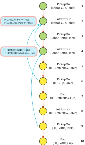
Figure 5 shows one of the sequences of actions planned by the symbolic planner for the task of making coffee. For each node, which is basic action, the symbolic planner queries to the geometric planner about the feasibility of the action. To show the need of backtracking at the very beginning, let us assume that for validating the 2nd node, which is to put the cup on the table, geometric planner has chosen a place, which is visible and reachable for human. At this stage, it has also maintained other solutions to put the cup, while maintaining the constraints. And when it reached at 4th node to validate the action of putting the bottle, the geomet-ric planner found that there exists no such place on the table, which is visible and reachable to human, to put the bottle. At this stage, instead of communicating the non-feasibility of the solution to the symbolic level, it will first try other possible solutions at geometric level itself. Here it will store additional constraint that the bottle should be put at a visible and reachable place to the human, and then it backtracks to previous nodes to try with other stored solutions. In the
cur-rent scenario, it will backtrack to 3rd node, but there is no other pickup configuration of bottle, which could facilitate the putting of the bottle. Then it backtracks to 2nd node and it found a set of other stored solutions to put the cup. So, it selects a new solution to put the cup, so that the discov-ered constraint about putting the bottle also satisfied. Then it again starts validating from that node onwards.
PickupOn
(Robot, Cup, Table) 1
PutdownOn
(Robot, Cup, Table) 2
PickupOn
(Robot, Bottle, Table) 3
PutdownOn
(Robot, Bottle, Table) 4
PickupOn (H1, CoffeeBox, Table) 5 PickupOn (H1, Cup, Table) 6 Pour (H1, CoffeeBox, Cup) 7 PutdownOn (H1, CoffeeBox, Table) 8 PickupOn (H1, Bottle, Table) 9 Pour (H1, Bottle, Cup) 10 (H1,Cup).visible==True; (H1,Cup).Reachable==True; (H1, Bottle).visible==True; (H1, Bottle).Reachable==True;
Figure 5: An example of a plan for coffee making scenario.
Similarly, on the later stage of validation, at node 6, hu-man has to pick the cup, but let us assume that unaware of this task during the first iteration, the robot has decided to put the cup and bottle in such a way that human could not take the cup. In this case also a similar backtracking will oc-cur with additional discovered constraint, that human should be able to pick the cup.
Backtracking at Symbolic level
It may be the case that even after backtracking and explor-ing all the possible solution at geometric level, the feasibil-ity of a particular node of symbolic plan could not be val-idated. In that case, the geometric planner would inform to the symbolic planner about non-availability of solution. Then the symbolic planner could decide to explore another (sub)branch of its plan.
In our example of coffee making, if the geometry fails because of the absence of a stable position to put the bot-tle down, the symbolic planner may switch to an alternative solution where the robot ”gives” the object directly to the human. If all actions are valid at both levels, symbolic and geometric, we can say that we have a valid plan.
Conclusion
We have devised a new and more elaborate task planning scheme, which extends the Asymov scheme and which ex-hibits the following features:
• The HTN planning scheme opens the possibility to pro-vide more information about the context to the geometric planner through a set of constraints that should be taken into account at geometric level.
• A geometric reasoning systems that is able to deal with elaborate requests concerning the achievement of situa-tions that are generally expressed at symbolic level. This has been made possible thanks to its ability to deal not only with path planning but also with spatial perspective taking, and human-robot cooperative object manipulation actions.
• A task planning scheme which provides a context for backtracking at symbolic as well as at geometric level and for various cost-based plan enhancement strategies.
Acknowledgments
The research leading to these results has received fund-ing from the European Community’s Information and Communication Technologies Seventh Framework Program FP7/2007-2013 under grant agreement no 215805, the CHRIS project and from ANR Psirob AMORCES project.
References
Alami, R.; Sim´eon, T.; and Laumond, J. 1990. A Geo-metrical approach to planning manipulation tasks. the case of Discrete placements and Grasps. In Robotics Research : The Fifth International Symposium.
Alili, S.; Alami, R.; and Montreuil, V. 2008. A task plan-ner for an autonomous social robot. In The 9th Interna-tional Symposium on Distributed Autonomous Robotic Sys-tems 2008 (DARS2008) in Tsukuba International Congress Center, Tsukuba, Ibaraki, Japan.
Alili, S.; Warnier, M.; Ali, M.; and Alami, R. 2009. Plan-ning and plan-execution for human-robot cooperative task achievement. 19th International Conference on Automated Planning and Scheduling (ICAPS ’09).
Cambon, S.; Alami, R.; and Gravot, F. 2009. A hybrid ap-proach to intricate motion, manipulation and task planning. The International Journal of Robotics Research28(1):104– 126.
Cambon, S.; Gravot, F.; and Alami, R. 2004. A robot task planner that merges symbolic and geometric reason-ing. In 16th European Conference on Artificial Intelligence (ECAI’2004), 895–899.
Ghallab, M.; Nau, D.; and Traverso, P. 2004. Automated Planning - theory and practice. Morgan Kaufmann Publish-ers.
Hoffmann, J. 2003. The metric-ff planning system: Trans-lating “ignoring delete lists” to numeric state variables. Journal of Artificial Intelligence Research20(20):291–341. Lozano-Perez, T.; Jones, J.; and Mazer, E. 1987. Handey: A robot system that recognizes, plans and manipulates. In ICRA.
Marin Urias, L. F.; Sisbot, E.; and Alami, R. 2008. Ge-ometric tools for perspective taking for human-robot inter-action. In Mexican International Conference on Artificial Intelligence (MICAI 2008). 11 pages.
Nau, D.; Au, T. C.; Ilghami, O.; Kuter, U.; and et al. 2003. Shop2: An htn planning system. Journal of Artificial Intel-ligence Research.
Pandey, A. K., and Alami, R. 2010. Mightability maps: A perceptual level decisional framework for co-operative and competitive human-robot interaction. In submitted to IEEE/RSJ International Conference on Intelligent Robots and Systems.
Sim´eon, T.; Laumond, J.-P.; Cort`es, J.; and Sahabani, A. 2003. Manipulation planning with probabilistic roadmaps. International Journal Robotic Research20(20):291–341. Sisbot, E.; Marin Urias, L. F.; and Alami, R. 2007. Spa-tial reasoning for human robot interaction. In IEEE/RSJ In-ternational Conference on Intelligent Robots and Systems, 2281–2287.