HAL Id: hal-02322493
https://hal.archives-ouvertes.fr/hal-02322493
Submitted on 4 Mar 2020
HAL is a multi-disciplinary open access
archive for the deposit and dissemination of
sci-entific research documents, whether they are
pub-lished or not. The documents may come from
teaching and research institutions in France or
abroad, or from public or private research centers.
L’archive ouverte pluridisciplinaire HAL, est
destinée au dépôt et à la diffusion de documents
scientifiques de niveau recherche, publiés ou non,
émanant des établissements d’enseignement et de
recherche français ou étrangers, des laboratoires
publics ou privés.
Combustion Characteristics of Ammonia in a Modern
Spark-Ignition Engine
Charles Lhuillier, Pierre Brequigny, Francesco Contino, Christine
Mounaïm-Rousselle
To cite this version:
Charles Lhuillier, Pierre Brequigny, Francesco Contino, Christine Mounaïm-Rousselle. Combustion
Characteristics of Ammonia in a Modern Spark-Ignition Engine. Conference on Sustainable Mobility,
Oct 2019, Catane, Italy. �10.4271/2019-24-0237�. �hal-02322493�
Combustion Characteristics of Ammonia in a Modern Spark-Ignition Engine
Charles LHUILLIER, Pierre BREQUIGNY, Francesco CONTINO, Christine ROUSSELLE
Abstract
Ammonia is now recognized as a very serious asset in the context of the hydrogen energy economy, thanks to its non-carbon nature, competitive energy density and very mature production, storage and transport processes. If produced from renewable sources, its use as a direct combustion fuel could participate to the flexibility in the power sector as well as help mitigating fossil fuel use in certain sectors, such as long-haul shipping. However, ammonia presents unfavorable combustion properties, requiring further investigation of its
combustion characteristics in practical systems. In the present study, a modern single-cylinder spark-ignition engine is fueled with gaseous ammonia/air mixtures at various equivalence ratios and intake pressures. The results are compared with methane/air and previous ammonia/hydrogen/air measurements, where hydrogen is used as combustion promoter. In-cylinder pressure and exhaust
concentrations of selected species are measured and analyzed. Results show that ammonia is a very suitable fuel for SI engine operation, since high power outputs were achieved with satisfying efficiency by taking advantage of the promoting effects of either hydrogen enrichment or increased intake pressure, or a combination of both. The performances under NH3 fueling compare well with
those obtained under methane operation. High NOx and unburned NH3 exhaust concentrations were also observed under fuel-lean and
fuel-rich conditions, respectively, calling for additional mitigation measures. A detailed combustion analysis show that hydrogen mainly acts as an ignition promoter. In the engine, pure ammonia combustion is assumedly mainly driven by the ignition kinetics of ammonia and the flame response to turbulence rather than by the laminar burning velocity.
Introduction
Ammonia (NH3) was recently attributed a serious role as a
sustainable energy carrier in a report from the International Energy Agency on The Future of Hydrogen [1]. Hydrogen (H2) is
increasingly considered as a major asset in the context of the present and upcoming energy transition towards variable renewable energy sources, and this report illustrates the currently growing interest in using ammonia for energy storage, transport and supply, as part of the hydrogen economy. In this report, the most promising uses of ammonia as a fuel are maritime shipping, power generation, and long-haul or heavy-duty truck transport, that all imply combustion. The potential of ammonia as a carbon-free sustainable fuel has raised renewed interest in the academic literature of the past decade, as well as in the industry [2]. Indeed, it is an efficient hydrogen carrier with 17.8% of hydrogen by mass and it can be stored and shipped in liquid form under mild conditions, as shown in Table 1. Along with a Lower Heating Value (LHV) of 18.8 MJ/kg, this gives ammonia a better volumetric energy density than hydrogen and makes it a competitive energy carrier in specific cases. Moreover, it could soon be produced economically directly from water, air and renewable energy sources, and since its combustion releases no carbon dioxide, a life cycle analysis by Bicer and Dincer [3] showed that greenhouse gas emissions could be reduced by almost a factor three by using ammonia-fueled vehicles instead of gasoline vehicles. The
well-known cooling properties of ammonia might also be beneficial in the context of its use as a transportation fuel as discussed by Zamfirescu and Dincer [4].
However, ammonia deployment as a fuel still faces some challenges since it is corrosive and presents unfavorable combustion properties, as illustrated in Table 1 by its low Laminar Burning Velocity (LBV), high auto-ignition temperature and narrow flammability range. The latter is simultaneously a safety benefit, since accidental ammonia fires or explosions are less likely to happen in case of NH3 leakage
than with conventional fuels or hydrogen.
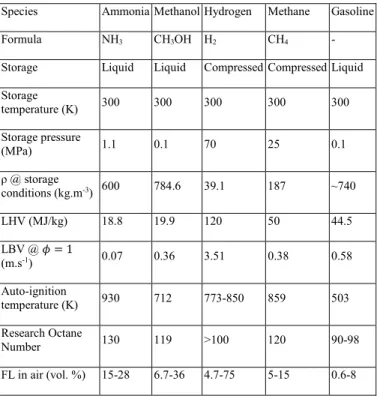
Table 1. Ammonia properties and comparison with other fuels at 300 K and 0.1 MPa, unless stated otherwise. Data from [5–7].
Species Ammonia Methanol Hydrogen Methane Gasoline Formula NH3 CH3OH H2 CH4 -
Storage Liquid Liquid Compressed Compressed Liquid Storage temperature (K) 300 300 300 300 300 Storage pressure (MPa) 1.1 0.1 70 25 0.1 ρ @ storage conditions (kg.m-3) 600 784.6 39.1 187 ~740 LHV (MJ/kg) 18.8 19.9 120 50 44.5 LBV @ 𝜙 = 1 (m.s-1) 0.07 0.36 3.51 0.38 0.58 Auto-ignition temperature (K) 930 712 773-850 859 503 Research Octane Number 130 119 >100 120 90-98 FL in air (vol. %) 15-28 6.7-36 4.7-75 5-15 0.6-8
Thus, several research teams recently focused on ammonia
combustion in order to overcome those challenges, as summarized by Valera-Medina et al. [7]. Several practical technologies and end-uses were studied, such as gas turbines [8], compression- and spark-ignited Internal Combustion Engines (ICE). Investigating ammonia combustion in ICE serves the global understanding of ammonia properties and it could be particularly useful for future maritime engines, truck engines or stationary power generators applications. The dual fuel approach was widely studied experimentally in Compression-Ignition (CI) engines, using kerosene, diesel, dimethyl-ether or hydrogen from ammonia dissociation as a pilot fuel to promote the auto-ignition [9–14]. Early engine studies (1960’s) demonstrated possible single fuel use of NH3 in CI engines but at
In order to avoid carrying several fuel tanks for pilot injection and to take advantage of ammonia’s high octane rating (Table 1), it appears reasonable to use Spark-Ignition (SI) to initiate the combustion in an ICE. Concurrently with the previously mentioned early CI engine studies, Cornelius et al. [17], Sawyer et al. [18] and Starkman et al. [19] conducted SI engine studies with ammonia as a fuel. Cornelius et al. reported poor engine performance under normally loaded conditions and a compression ratio (CR) of around 10:1 as compared to gasoline operation, as well as high NH3 exhaust concentrations.
The use of several strategies including improved ignition systems, supercharged operation, increased CR and hydrogen blending in the NH3 fuel allowed them to greatly improve the performances and
reduce the emissions. The optimal H2 fraction to be added to the fuel
was found to be about 2% by mass of fuel, which is about 15% by volume. Intake hydrogen was produced in-situ by NH3 dissociation
using a dedicated device. NOx emissions were found to be
comparable with the ones under gasoline operation, but increased as the indicated efficiency increased. Starkman et al. additionally showed in their Collaborative Fuel Research (CFR) engine study that indicated efficiencies were degraded during NH3 fuel operation when
compared to gasoline and that it implied a higher specific consumption. They recommended keeping a minimum amount of hydrogen in the premixed gaseous blend as a critical requirement for satisfying engine operation.
More recently, several research groups tested ammonia along with gasoline in CFR, using different injection and combustion promotion strategies engines [20–23]. They showed successful substitution of gasoline with ammonia with good engine performance and reduced unburned hydrocarbons and CO emissions. NH3 exhaust emissions
are the main issue and NOx exhaust concentrations were shown to decrease, resp. increase with the fraction of ammonia in the fuel when using indirect, resp. direct gaseous injection. Ryu et al. proposed to partially dissociate NH3 in a dedicated catalyst prior to
injection, in order to improve the combustion efficiency and that resulted in significantly reduced nitrogen-based emissions, especially at low loads [23]. Ammonia combustion enhancement by in-situ NH3
dissociation was also investigated by Frigo et al. [24,25] and Pozzana et al. [26] not in a CFR but in a commercial two-cylinder SI engine (CR = 10.7:1) equipped with a dedicated catalytic reformer. In [27], the same authors reported NH3 emissions surprisingly under 100
ppm. Mørch et al. [6] similarly studied NH3/H2 blends fueled in a SI
engine (CFR) at various CR with NH3 provided from in-situ
heat-assisted desorption from a metal ammine complex. They reported an increased efficiency compared with gasoline operation due to the possibility of knock-free CR increase. A focus on nitrogen-based pollutant emissions from a 80 vol.% NH3 / 20 vol.% H2 fueled CFR
engine was proposed by Westlye et al. [28]. NH3 slip of several
hundreds of ppm is observed in the exhaust and tentatively explained by a rapid hydrogen flame propagation followed by a bulk
combustion, while some ammonia is trapped in the piston crevices and cannot fully burn. Higher CR causes the increase of both NOx and NH3 emissions. Westlye et al. also demonstrated the feasibility of
SCR systems as a function of the exhaust temperature and NOx to NH3 ratio, if an additional NH3 amount is introduced in the
after-treatment system under controlled conditions.
Therefore, a strong evidence of the suitability of ammonia as a low-carbon SI engine fuel is reported in the literature. However, very few studies successfully using pure ammonia as a fuel were published, to the best knowledge of the present authors. Moreover, most of the available engine data with NH3 fuel were obtained in outdated or
basic engine geometries. Thus, it appeared interesting to the present authors to conduct a systematic experimental study on ammonia combustion in a modern all-metal single-cylinder SI engine, focusing on engine performance, combustion characteristics and pollutant emissions. The set-up is introduced in the dedicated section in the following. The first part of the study aimed at determining the satisfying limits of operation of the present engine in its as-is design
in terms of mixture composition and was presented in [29]. Premixed gaseous ammonia/hydrogen/air mixtures with up to 60 vol.% H2 in
the fuel were fueled in the engine for equivalence ratios ranging from 0.6 to 1.2. It was found that best performances were reached for H2
fractions in the fuel smaller than 20 vol.%, consistently with the literature data. The major role of hydrogen was shown to be as ignition promoter, having an exacerbated effect during the
combustion initiation phase. Very high NH3 and NOx emissions were
recorded, in accordance with the literature. In the second part of the present systematic study, a new gas analyzer was implemented for exhaust H2 and O2 measurements during new engine experiments,
allowing to close the species balance and to analyze the combustion efficiency of near stoichiometric ammonia/hydrogen/air mixtures with 5 to 15 vol.% H2 [30]. It was shown that increased H2
enrichment improves the cyclic stability of the engine, as well as the combustion efficiency, leading to reduced NH3 exhaust
concentrations but higher NOx concentrations. Significant H2 exhaust
concentrations were reported, indicating a partial NH3 decomposition
during or subsequent to the combustion process.
The present paper shows new experimental engine measurements aiming at demonstrating the particularities of pure ammonia combustion in the same commercially available SI engine, when compared to slightly hydrogen-enriched ammonia and pure methane, as the reference case conventional fuel. The focus of the present paper is set on pure ammonia combustion in the engine, because this would likely be the most efficient practical mode, given that no hydrogen tank and no energy-demanding ammonia dissociation device would be required. In the first part, the experimental setup is introduced. New measurement data from engine experiments are then presented. Discrepancies in terms of performance and pollutant emissions are discussed between NH3, NH3/H2 and CH4 fuels. A
detailed discussion on the combustion features of pure ammonia in the present SI engine is then proposed.
Experimental Method
Experimental Setup
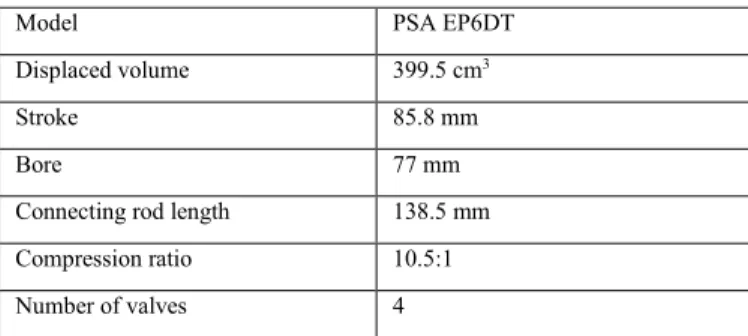
Engine experiments were conducted in a modern cylinder four-stroke SI Gasoline Direct Injection (GDI) engine modified to become a single-cylinder engine by fueling only one out of four cylinders. The description of the engine setup is partly reproduced here from [30] for the sake of completeness. Table 2 presents the engine specifications.
Table 2. Engine specifications.
Model PSA EP6DT
Displaced volume 399.5 cm3
Stroke 85.8 mm
Bore 77 mm
Connecting rod length 138.5 mm Compression ratio 10.5:1 Number of valves 4
The engine is driven by an electric motor at a fixed engine speed of 1500 rpm. The main shaft is equipped with a Kübler optical encoder for angular position monitoring with a 0.1 Crank Angle Degree (CAD) resolution. A water-cooled AVL piezoelectric pressure transducer with a 0.1 CAD resolution provides in-cylinder pressure measurements. Its measuring range is 0 – 25 MPa. Engine intake and exhaust temperature and pressure are monitored using type K
thermocouples and piezo-resistive absolute pressure transducers, respectively. The absolute cylinder pressure is obtained by equalizing the in-cylinder pressure and the mean absolute intake pressure (Pin)
20 CAD after inlet valve opening. The spark plug used is the original one with a coil charging time set to 2 ms. Ammonia, methane and air gaseous flows are measured and controlled using Brooks thermal mass flowmeters with ± 0.7% accuracy, preheated to the intake temperature of 323 K and premixed in an intake plenum before injection. A scheme of the experimental setup is shown in Figure 1.
Figure 1. Layout of the experimental setup.
The wet exhaust gases are analyzed using a Gasmet Fourier Transform Infrared (FTIR) spectrometer to assess H2O, NOx and
NH3 concentrations. This equipment allows simultaneous quantitative
measurement of many gaseous species with a good time resolution and accuracy, if the interferences between the species of interest are correctly identified and taken into account in the analysis settings. This has been done in the present work and the analysis ranges are presented in Table 3 for the different species. However, water vapor is a major interfering compound in infrared wavelengths, and its presence in the exhaust sample is inevitable due to the interest in measuring H2O and NH3, that would otherwise condensate along with
H2O. Even though its presence is accounted for in the interferences
corrections, the authors believe that it may lead to some uncertainties in the exhaust gas measurements, in addition with other cross-component interferences. After preliminary verifications, the authors estimated the maximal uncertainty on the species concentrations to be low enough to maintain a very good qualitative significance of the present measurement data.
Table 3. Analysis ranges for the FTIR species measurement.
Species Wave number range (cm-1)
H2O 3950 – 4240
N2O 2000 – 2250
NO 1840 - 2080
NO2 1250 - 1720
NH3 1000 - 1240
In addition, an ADEV gas analyzer is used on a dry exhaust gas sample for H2 (thermal conductivity) and O2 (paramagnetic)
measurement. The water vapor measurement done with the FTIR analyzer is used for wet correction. The accuracy of the H2 and O2
analyzers is ± 1 % (range 0 – 20 % H2, 0 – 21 % O2). A Horiba
Mexa7100 5 gases analyzer is used for NOx, CO, CO2 and HC
measurements in the case of methane operation. The use of this analyzer is strictly restricted to pure methane operation due to the suspicion of possible ammonia or ammonium contamination of the sensitive internal sampling system in case of ammonia operation. The use of this analyzer in the case of methane was preferred for practical reasons.
Operating Conditions
The global stoichiometric reaction of NH3/H2/air combustion is as:
(1 − 𝑥H2)NH3+ 𝑥H2H2+ 3 − 𝑥H2 4 (O2+ 3.76N2) → ⋯ (3 − 𝑥H2 2 ) H2O + ( 1 − 𝑥H2 2 + 3.76 ∗ 3 − 𝑥H2 4 ) N2 (1) where 𝑥H2 is the hydrogen molar fraction in the fuel mixture.
Non-stoichiometric mixtures are defined by the global equivalence ratio:
𝜙 = 𝑋H2+ 𝑋NH3 𝑋air (𝑋H2+ 𝑋NH3 𝑋air )st (2).
𝑋s represents the molar fraction of the species s in the reactive
mixture. The stoichiometric air/fuel ratio by mass is around 6 for pure NH3 fuel and thus about twice smaller than for gasoline and three
times smaller than for methane. The engine is operated at a fixed speed and fueled with near stoichiometric ammonia/air (Fuel A) or methane/air (Fuel C) gaseous mixtures. Ammonia/hydrogen/air data (Fuel B) were taken from [30]. The intake temperature is kept constant for practical reasons but the intake pressure is varied, in order to simulate various engine loads. The spark-ignition timing is set at Maximum Brake Torque (MBT) to ensure the maximum net indicated mean effective pressure (IMEPn), a quantification of the
work provided by the combustion in the absence of direct torque measurements. The friction losses caused by the three deactivated pistons make the latter irrelevant. Cycle-to-cycle variability is considered by recording 100 consecutive pressure cycles for each test. Averaged values over 100 cycles are presented in this paper. Satisfying cyclic stability is considered when the coefficient of variation of the IMEPn over 100 cycles, COV(IMEPn), does not
exceed 5%. Thus, only conditions satisfying this criterion are analyzed in the present work. This means in particular, that no misfire were observed over 100 cycles for the presented conditions, since a misfire automatically causes the COV(IMEPn) to exceed the
set limit. Most of the tested operating conditions exhibit
COV(IMEPn) < 1%. The range of investigated operating conditions is
summarized in Table 4.
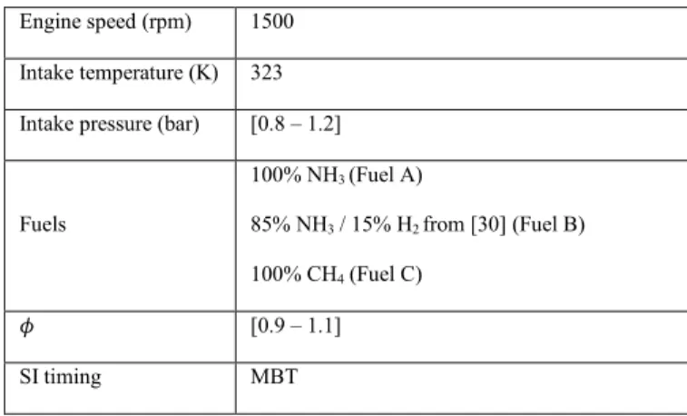
Table 4. Overview of the operating test conditions.
Engine speed (rpm) 1500 Intake temperature (K) 323 Intake pressure (bar) [0.8 – 1.2]
Fuels 100% NH3 (Fuel A) 85% NH3 / 15% H2 from [30] (Fuel B) 100% CH4 (Fuel C) 𝜙 [0.9 – 1.1] SI timing MBT
Results and Discussion
Engine Performance
A major outcome of the present study is the demonstration of successful engine operation under pure ammonia fueling. Figure 2 presents the optimized spark ignition timings that were required to achieve the maximum power output, which often corresponds to the minimum cyclic variability, for pure ammonia (Fuel A), hydrogen-enriched ammonia (Fuel B) and for comparison, methane (Fuel C) engine operation. It appears that stable operating mode under pure ammonia fueling could be achieved for intake pressures equal and higher than 1.0 bar for all tested equivalence ratios if the spark ignition timing is significantly advanced, in order to compensate for the slow combustion dynamics of NH3. The COV(IMEPn) was found
greater than 20% for pure ammonia at Pin = 0.8 bar, with a very poor
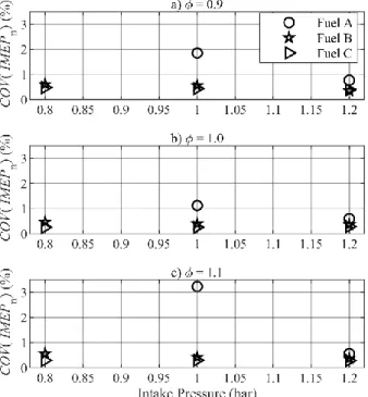
cyclic stability and the occurrence of misfires, even when varying the SI timing. Increasing the engine load via the intake pressure leads to an improved cyclic stability when optimizing the SI timing in the case of pure NH3 as shown in Figure 3 with the COV(IMEPn).
NH3/H2 and CH4 fuels exhibit stable operation over the whole range
of investigation. As expected, adding hydrogen to the fuel blend significantly displaces the optimal SI timing towards TDC, leading to SI timing values comparable with methane operation, as shown in Fig. 2. Moreover, hydrogen addition also promotes cyclic stability when the intake pressure is decreased, thus allowing stable operation without significantly increasing the spark advance, as shown in Fig. 3. As to optimize the efficiency, the increase of the engine
compression ratio could be considered in future applications, the previous observation needs to be taken into account, since a very early spark ignition timing would partly neutralize the
thermodynamic benefits of an increased CR.
Figure 2. Spark Ignition timing at MBT under stable operating conditions.
Figure 3. Coefficient of variation of the IMEPn.
Figure 4 presents the IMEPn averaged on 100 consecutive cycles for
the three fuels as a function of the intake pressure and equivalence ratios. It is important to note here that the volumetric addition of hydrogen does not change significantly the energy content of the ammonia-based fuel/air mixtures. Indeed, the higher LHV by mass of H2 is compensated by its small molecular weight. NH3 thus exhibits a
higher molar LHV than H2, which in turn is balanced by the greater
air-fuel ratios required for ammonia combustion. This justifies the lack of IMEPn differences between the NH3/air and 85% NH3/15%
H2/air mixtures as observed in Fig. 4. For all mixtures, the IMEPn
increases from lean to stoichiometric and then stabilizes between stoichiometric and rich conditions. This general trend is expectable, since the amount of fuel introduced in the cylinder increases with increasing 𝜙, while the lack of available air limits the energy conversion above stoichiometric conditions. This is particularly noticeable under methane operation, where the IMEPn peaks around
stoichiometry and decreases when moving towards lean or rich conditions. For Pin = 1.0 bar, the pure ammonia rich mixture
exhibited a slightly degraded cyclic stability, that could explain the decrease of the IMEPn between stoichiometric and rich conditions.
The use of CH4 as a fuel yields higher IMEPn than NH3 blends,
especially at high intake pressures. However, increasing the intake pressure allows operating the engine with high-ammonia-content fuels and higher power outputs, as illustrated by increased IMEPn,
with values greater than 8 bar for Pin = 1.2 bar, that is significantly
higher than full load methane operation. Therefore, supercharged operation could allow reproducing the power outputs obtained with conventional fuels when operating ammonia-based fuels.
Figure 4. Net Indicated Mean Effective Pressure for the various fuels and intake pressures.
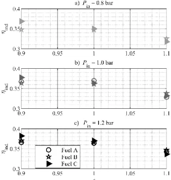
In order to make meaningful comparisons, the power output, given by the IMEPn is compared with the power introduced in the cylinder on
a LHV basis in Figure 5. A higher intake pressure leads to a slight increase of the indicated efficiency in most cases. The indicated efficiency decreases with increasing equivalence ratio in all cases, but very slightly between 𝜙 = 0.9 and 𝜙 = 1.0 for NH3-based fuel blends,
for which the best values lie above ηind = 36 % in loaded conditions.
The influence of hydrogen-enrichment on the indicated efficiency is once again neither consistent nor quantitatively significant. When compared with the indicated efficiency under methane operation (filled triangle in Fig. 4), ammonia performs equally or better for stoichiometric and rich mixtures, while staying comparable under lean conditions. This indicates that the IMEPn benefit observed under
CH4 fueling is mainly due to the higher LHV of methane, and thus
higher energy content of the CH4/air mixtures when compared with
NH3 fueling.
Figure 5. Indicated efficiency for the various fuels and intake pressures.
Pollutant Emissions
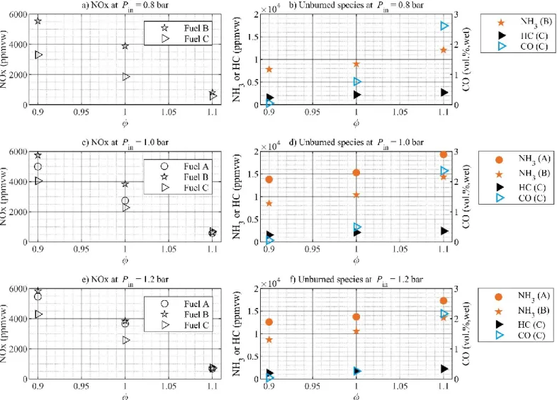
While all carbon-based engine emissions are wiped out by using ammonia as a fuel, a major remaining concern is the occurrence of important nitrogen-based emissions. Therefore, it is of primary interest to assess those emissions in the case of SI engine combustion. Figure 6 shows measured pollutant species exhaust concentrations as a function of the equivalence ratio for the different intake pressures and fuel compositions investigated presently. The pollutant species are NOx and NH3 for ammonia-based fuels and NOx, HC and CO for
methane. Essentially, the NOx exhaust concentrations increase when the intake pressure is increased, assumedly due to higher flame temperatures, while the unburned species concentrations decrease, due to improved combustion efficiency. However, unburned NH3
concentrations increase slightly with increasing Pin in the case of Fuel
B (85% NH3 / 15% H2) as shown in Figs. 6b, 6d and 6f. This might
be explained by the crevice mechanism proposed by Westlye et al. [28], assuming a fast hydrogen flame initiating a subsequent bulk NH3 combustion. In that case, the amount of NH3 trapped in the
crevices and unable to benefit from the hydrogen-assisted combustion is determined at the time of the hydrogen flame quenching near the crevice opening. Increasing the intake pressure leads to a higher amount of trapped NH3, which might explain the previous
observation for Fuel B. Care should however be taken, in view of the relatively small magnitude of the discussed NH3 variations with
increased Pin and the associated measurement uncertainties.
For ammonia-based fuels (Fuel A and B), NOx emissions decrease, while NH3 emissions increase as 𝜙 is increased, as shown in Fig. 6.
For the former species, this is expected, since NOx formation strongly depends on the availability of oxygen. Regarding the latter, more NH3 introduced logically leads to more unburned NH3 in the
exhaust. The concentrations are very high for both pollutants, reaching up to 6000 ppmvw for NOx under hydrogen-enriched lean conditions and close to 20 000 ppmvw (2 vol.%) for NH3 for rich
ammonia/air mixtures. Hydrogen-enrichment causes higher NOx emissions for mixtures up to stoichiometry and Pin = 1.0 bar (Fig. 6c),
assumedly due to higher flame temperatures, but similar or identical values in the other cases where pure NH3 operation was possible. In
addition, NOx emissions observed during CH4 operation follow the
same decreasing trend with oxygen depletion, but exhibit
significantly lower values for lean mixtures at low intake pressures (Fig. 6a), with less than 3500 ppmvw. However, the gap with NOx emissions of lean to stoichiometric NH3-based fuels becomes smaller
under full load and supercharged operation. Noticeably, all rich mixtures exhibit the same exhaust concentration of NOx, indicating a prominent role of oxygen availability in the NOx formation. The role of fuel-bound nitrogen is not explicitly investigated here, but it is clear that is does not influence the order of magnitude of the NOx emissions when compared to a hydrocarbon fuel, especially for rich mixtures. Hydrogen addition to ammonia causes significantly lower NH3 emissions, thanks to an improved NH3 combustion efficiency.
Since NOx and NH3 emissions follow opposite trends, it appears that
a trade-off as well as after-treatment strategies will be necessary, since the observed levels are likely to exceed largely the acceptable limits. Westlye et al. [28] showed through simulations that their engine exhaust temperatures could be suitable for efficient operation of a SCR catalyst in the after-treatment system. The temperature range 573 K – 723 K is proposed as an optimum and corresponds well with the values observed immediately after the engine in the present study. However, the issue of pollutant control is not specific to ammonia-fueled engines, since significant amounts of unburned HC and CO were measured in the exhaust gas during CH4 operation.
CO2 emissions of about 9 vol.% (wet) should also be reported under
Figure 6. Pollutant concentrations in the wet engine exhaust. Left: NOx emissions. Right: Unburned species concentrations (NH3 for ammonia-based fuels, HC and CO
Combustion Analysis
Some studies in the literature also reported H2 emissions for NH3
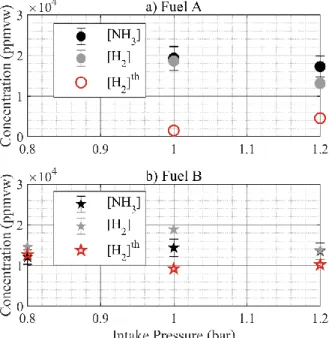
-fueled SI engines [17,31]. In order to assess the combustion completeness and to conduct further analysis of the specific aspects of ammonia combustion, exhaust H2 measurements were conducted.
A comparison of H2 and NH3 exhaust concentrations is presented in
Figure 7 for 𝜙 = 1.1, in order to extend the data presented in [30]. Measured values for lower equivalence ratios are below the accuracy of the H2 analyzer and are thus not depicted here. This is assumedly
due to the total consumption of H2 in the presence of excess air, and
consistent with the observations of Cornelius et al. [17].
The measurements in Fig. 7 show very similar values and trends for the concentrations of H2 and NH3. The very high H2 concentrations
with respect to the intake proportions indicate H2 formation from
NH3 dissociation during or after the combustion process. This is
verified by comparing the measurements with a constructed value for the H2 concentration, obtained by assuming complete combustion as
follows: [𝐻2]𝑡ℎ= [𝐻2]𝑜𝑢𝑡𝑒𝑥𝑐𝑒𝑠𝑠+ 3 2∙ ([𝑁𝐻3]𝑜𝑢𝑡 𝑒𝑥𝑐𝑒𝑠𝑠− [𝑁𝐻 3]𝑜𝑢𝑡𝑚𝑒𝑎𝑠𝑢𝑟𝑒𝑑) (3),
where the subscript “out” stands for concentrations in the exhaust gases. The factor 3/2 comes from the stoichiometric proportions of ammonia dissociation and is applied to the difference between the theoretical ammonia concentration that should be observed due to excess fuel injection assuming complete combustion, and the actual concentration that was measured in the exhaust gas. Thus, the assumption is made that all missing ammonia has been dissociated to H2 and N2 during the combustion process. The calculated values
agree qualitatively with H2 measurements in the case 𝑥𝐻2 = 15 %
(Fig. 7b). This suggest a combustion efficiency close to 100% in the latter case. The discrepancies observed between [H2] and [H2]th for
pure ammonia (Fuel A) in Fig. 7a are assumedly due to incomplete combustion: the unburned NH3 originates from excess NH3 at the
intake and the unburned H2 is mainly a result of incomplete
combustion. While the previous assumptions have to be further explored and validated, the measured presence of significant quantities of H2 in the exhaust under rich conditions could suggest
the use of techniques such as exhaust gas recirculation. The combustion efficiency is shown in Figure 8 and defined as follows: 𝜂c= 1 − 𝐸f,out 𝐸f,in (4), with 𝐸f= ∑ 𝑛s∙ 𝐿𝐻𝑉s (5),
the energy contained in the fuel as measured at the intake and at the exhaust (subscript in and out respectively) on the basis of the LHV of each fuel species s. Pure ammonia fuel shows a relatively poor combustion efficiency below 95% in all conditions, but it increases when the intake pressure is increased. Hydrogen-enrichment leads to an improved combustion efficiency, as already described in [30], allowing to approach closely the efficiency of CH4 fuel in the
stoichiometric and rich cases, thus not exceeding 96% for the lean mixture. In comparison, lean CH4 operation demonstrates a
combustion efficiency above 98%.
Figure 7. Comparison of NH3 and H2 exhaust concentrations for 𝜙 = 1.1.
Figure 8. Combustion efficiency.
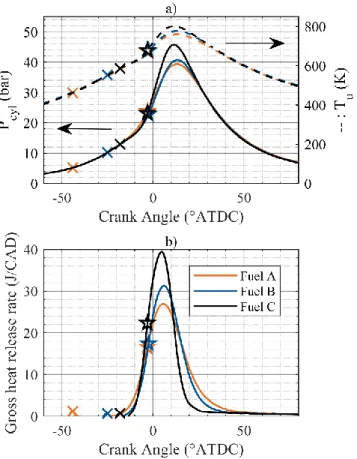
In order to gain further understanding of the combustion behavior of NH3, in-cylinder pressure traces were analyzed and used to calculate
the net and gross heat release using the wall heat loss correlation of Hohenberg [32]. This classical analysis allows defining the combustion phases, and particularly CA10, which is the crank angle at which 10% of the total introduced mass has burned. Moreover, a classical two-zone model (burned and unburned zone) allows calculating an estimation of the average temperature of the fresh gases during the engine cycle. A representative example of such an analysis is shown in Figure 9 for Pin = 1.0 bar and 𝜙 = 1.0. It can be
observed in Fig. 9a that the optimal SI timing has a synchronizing effect on the pressure curves obtained with different fuels. For instance, the maximal pressure is reached at the approximately same timing for methane, ammonia and hydrogen enriched-ammonia. The
CA10 are also very close. It should be remembered here that the SI timing was chosen in order to maximize the IMEPn in each case.
This is further confirmed in Fig. 9b, where the heat release rates are approximately centered around the same timing. However, the pressure rise and thus the heat release rate from methane combustion present a significantly higher magnitude than ammonia-based combustion. The heat release happens stronger and faster, the heat release rate decreasing noticeably faster after TDC than for ammonia-based mixtures. Regarding NH3 and NH3/H2 combustion, the
differences are less significant, except during the initiation phase of the combustion. Indeed, the time between spark ignition and the CA10 is significantly reduced when hydrogen is added to the fuel. Consecutively to that initiation phase, the combustion happens in a similar manner, even though the heat release rate peaks slightly higher for the hydrogen-enriched case, accompanied by a slightly reduced overall combustion duration. The dynamics of ammonia combustion might thus provide explanations regarding the possibility of stable operation with low cyclic variation for a given set of operating conditions.
Figure 9. Pressure, temperature of the fresh gas mixture and gross heat release rate for various fuels at Pin = 1.0 bar and 𝜙 = 1.0. a) Solid lines: in-cylinder
pressure, dotted lines: estimated fresh gas temperature. b) Solid lines: gross HRR. Crosses: SI timing, pentagrams: CA10.
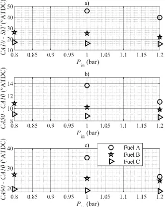
To further demonstrate the previous statements, the combustion phases as deduced from the heat release calculations are plotted in Figures 10 and 11 as functions of the equivalence ratio and intake pressure, respectively. The initiation phase CA10-SIT of pure ammonia is very long relative to the following phases and to the other fuels. Hydrogen-enrichment greatly reduces the duration of that initial phase, thus not reaching the speed of methane for that hydrogen fraction. The influence of the equivalence ratio is quite insignificant during the initial phase and the propagation phase CA50-CA10, but it does affect the combustion duration CA90-CA10 of ammonia-based fuels, that decreases when the equivalence ratio
increases. The combustion duration of pure ammonia is about 10 CAD longer than the one of lean methane, as seen in Fig. 10c.
Figure 10. Combustion phases as functions of the equivalence ratio for Pin =
1.2 bar.
Increased intake pressure leads to no significant changes on the duration of the combustion phases of methane, but leads to a slight acceleration of all phases for hydrogen-enriched ammonia and a significant acceleration of the combustion phases for pure ammonia, noticeably of the combustion duration, as shown in Figure 11. This indicates a higher sensitivity of pure ammonia combustion on the thermodynamic conditions during the engine cycle.
Figure 11. Combustion phases as functions of the intake pressure for 𝜙 = 1.1.
Therefore, laminar burning velocity calculations were conducted in a first approach to assess whether the global reaction kinetics could explain the different combustion behavior under the various operating conditions. In the case of methane, the LBV, 𝑆𝐿0, was calculated using
the PREMIX model in CHEMKIN and the GRI3.0 reaction mechanism [33]. In the case of NH3 and NH3/H2/air mixtures, the
LBV was calculated using the dedicated LBV correlation by Goldmann and Dinkelacker [34]. The initial conditions were chosen as the ones found during engine operation in the fresh gas mixture at CA10 under the assumption of a two-zone model. The pentagrams in Fig. 9a depict an example of such conditions. CA10 was chosen as the relevant thermodynamic state for a comparison, since it is a reliable estimation of the first stages of the flame propagation phase. It is uncertain, whether a proper flame is propagating during the previous stages of the combustion, due to the combustion initiation delay. The LBV results are presented in Figure 12. As expected, the LBV of methane/air flames is significantly higher than the one of ammonia/air and slightly-hydrogen-enriched ammonia/air flames. This partly explains the previously discussed differences observed in Figs. 9 - 11. Unsurprisingly, hydrogen-enrichment leads to an increase of the LBV for NH3-based mixtures. However, the LBV
does not fully elucidate the reasons that make pure ammonia engine operation possible in some cases and not in others, in particular for small intake pressures. Indeed, the LBV is slightly decreasing with increased intake pressure due to an unfavorable balance between increased fresh gas temperature and pressure. Moreover, it was possible in [30] to run the engine with NH3/H2 blends showing lower
LBVs than the one plotted in Fig.12for pure ammonia. Therefore, the LBV of NH3/air and NH3/H2/air mixtures is not relevant to assess
the suitability of a mixture for stable, misfire-free SI engine operation and it does not fully explain the beneficial influence of H2 on
ammonia combustion.
Figure 12. Calculated laminar burning velocity under the respective thermodynamic conditions in the fresh gas at CA10 during engine operation.
The experiments with NH3/H2/air mixtures show that H2 mainly acts
as an ignition promoter during the initiation phase when small fractions are added [30]. Further enrichment then significantly accelerates the combustion phases, as the effect of hydrogen on the combustion properties is becoming more important [29]. Therefore, the assumption of partial thermal NH3 dissociation to H2 and N2 in
the fresh gases under the combined effect of the compression and the spark could explain the successful engine operation with pure NH3, in
spite of unfavorable combustion properties. Moreover, it would explain the greater sensitivity of pure NH3 to the in-cylinder
thermodynamic conditions. In order to get a first insight about this assumption, numerical simulations where conducted for a stoichiometric NH3/air mixture using the reaction mechanism of
Shreshta et al. [35] in a closed adiabatic homogeneous reactor model from CHEMKIN. The temperature and pressure profiles where constrained as those in Fig. 9a and the volume could vary. The hydrogen mole fraction in the reactor is shown in Figure 13 as a function of the residence time. The result is not conclusive, since a very low, insignificant hydrogen production is observed. Therefore, additional investigations are required, perhaps with more developed models, in order to make conclusions on the assumption of NH3
dissociation in the fresh gases. Investigation of other combustion promoters, such as OH radicals, that could be produced before or during the initiation phase would also be of interest.
Figure 13. H2 mole fraction in a homogeneous reactor with a stoichiometric
NH3/air mixture under the conditions of Fig. 9a.
Summary and Conclusions
As ammonia is gaining increased interest as a sustainable fuel and has been validated as a suitable fuel for internal combustion engines, it is worth investigating the characteristics of a recent SI engine fueled with ammonia. Objectives are to assess the best operating conditions in the current configuration, propose a detailed analysis and provide useful data for comparisons and validation purposes. In the present study, new experiments were conducted in a recent PSA spark-ignition GDI engine used as a single-cylinder engine fueled with premixed ammonia/air and methane/air mixtures at a constant speed of 1500 rpm. Ammonia/hydrogen/air results from a previous study are presented for comparison purposes. The
parameters were the intake pressure, the fuel/air equivalence ratio and the fuel composition. The spark timing was set at MBT and the compression ratio was 10.5:1.
Engine operation under pure ammonia fueling is demonstrated for intake pressure equal and greater than 1.0 bar, with an important SI timing advance. Under hydrogen-enriched conditions, the engine can be operated with very low cyclic variability from part load to supercharged operation provided that the spark-ignition timing is correctly advanced. Increasing the intake pressure above 1.0 bar appears to be a suitable strategy to promote pure ammonia combustion due to more favorable thermodynamic conditions, leading to improved engine cyclic stability and power outputs comparable with full-load methane operation. The IMEPn obtained
with pure NH3 fueling are comparable with those obtained with CH4
and NH3/H2 fueling, and sometimes higher. The indicated efficiency
reaches maximal values close to 37% with lean ammonia/air mixtures, and the values exceed those of methane in some cases. Under lean conditions, very high NOx emissions up to 6000 ppmvw are found, with exacerbating effects of increased hydrogen fraction and intake pressure. NOx emissions decrease when the mixtures become richer down to less than 1000 ppmvw. Very high NH3
exhaust concentrations are measured, with unacceptable potential consequences on human health and the environment without additional. H2 exhaust concentrations of several percent are measured
for rich mixtures. The combustion efficiency of pure ammonia fuel is significantly lower than that of hydrogen-enriched ammonia and methane. The analysis of ammonia combustion confirms the promoting effect of H2 during the combustion initiation phase.
However, this effect is not simply reflected in the LBV of the mixtures. An attempt to simulate NH3 dissociation in the fresh gases
leads to no conclusive results. The main conclusions are as follows:
1. Ammonia is a suitable carbon-free fuel for modern SI engines, even in part-load operation when enriched with hydrogen. 2. Pure ammonia compares surprisingly well with a conventional
fuel (methane) regarding the engine performances.
3. Near-stoichiometric lean operation is recommended, since it provides satisfying power output and efficiencies, while mitigating both NOx and NH3 emissions, keeping them in the
same order of magnitude in the perspective of dedicated after-treatment systems. However, slightly rich operation with exhaust gas recirculation might be of interest, due to the presence of significant quantities of unburned H2 in the exhaust
gas.
4. The issue of pollutant emissions is of the same nature that in the case of conventional fuels. Its mitigation requires mainly engineering of after-treatment systems, even though further fundamental understanding of ammonia’s combustion mechanisms is required to minimize the sources of the emissions.
5. The laminar burning velocity is not the governing parameter to explain ammonia combustion in SI engines. Further
investigations will be conducted on turbulent flame
characteristics and intermediate species formation during the compression stroke and shortly after ignition, to provide further understanding on ammonia combustion.
References
[1] International Energy Agency, The Future of Hydrogen, 2019.
[2] Zamfirescu, C., Dincer, I., "Using ammonia as a sustainable fuel", J. Power Sources 185: 459–465, 2008, doi:
10.1016/j.jpowsour.2008.02.097.
[3] Bicer, Y., Dincer, I., "Life cycle assessment of ammonia utilization in city transportation and power generation", J. Clean. Prod. 170: 1594–1601, 2018, doi:
10.1016/j.jclepro.2017.09.243.
[4] Zamfirescu, C., Dincer, I., "Ammonia as a green fuel and hydrogen source for vehicular applications", Fuel Process. Technol. 90: 729–737, 2009, doi:
10.1016/j.fuproc.2009.02.004.
[5] Linstrom, P.J., Mallard, W.G., NIST Chemistry WebBook, NIST Standard Reference Database Number 69,National Institute of Standards and Technology,
https://webbook.nist.gov/, accessed Jul. 2019.
[6] Mørch, C.S., Bjerre, A., Gøttrup, M.P., Sorenson, S.C., Schramm, J., "Ammonia/hydrogen mixtures in an SI-engine: Engine performance and analysis of a proposed fuel system", Fuel 90: 854–864, 2011, doi:
10.1016/j.fuel.2010.09.042.
[7] Valera-Medina, A., Xiao, H., Owen-Jones, M., David, W.I.F., Bowen, P.J., "Ammonia for power", Prog. Energy Combust. Sci. 69: 63–102, 2018, doi:
10.1016/j.pecs.2018.07.001.
[8] Kobayashi, H., Hayakawa, A., Somarathne, K.D.K.A., Okafor, E.C., "Science and technology of ammonia combustion", Proc. Combust. Inst. 37: 109–133, 2019, doi: 10.1016/j.proci.2018.09.029.
[9] Reiter, A.J., Kong, S.C., "Demonstration of compression-ignition engine combustion using ammonia in reducing greenhouse gas emissions", Energy and Fuels 22: 2963– 2971, 2008, doi: 10.1021/ef800140f.
[10] Reiter, A.J., Kong, S.C., "Combustion and emissions characteristics of compression-ignition engine using dual ammonia-diesel fuel", Fuel 90: 87–97, 2011, doi: 10.1016/j.fuel.2010.07.055.
[11] Gill, S.S., Chatha, G.S., Tsolakis, A., Golunski, S.E., York, A.P.E., "Assessing the effects of partially decarbonising a diesel engine by co-fuelling with dissociated ammonia", Int.
J. Hydrogen Energy 37: 6074–6083, 2012, doi: 10.1016/j.ijhydene.2011.12.137.
[12] Gross, C.W., Kong, S.C., "Performance characteristics of a compression-ignition engine using direct-injection
ammonia-DME mixtures", Fuel 103: 1069–1079, 2013, doi: 10.1016/j.fuel.2012.08.026.
[13] Ryu, K., Zacharakis-Jutz, G.E., Kong, S.-C., "Performance characteristics of compression-ignition engine using high concentration of ammonia mixed with dimethyl ether", Appl. Energy 113: 488–499, 2014, doi:
10.1016/j.apenergy.2013.07.065.
[14] Pochet, M., Truedsson, I., Foucher, F., Jeanmart, H., Contino, F., "Ammonia-Hydrogen blends in Homogeneous-Charge Compression-Ignition Engine", SAE Technical Paper 2017-24-0087, 2017, doi: 10.4271/2017-24-0087. [15] Pearsall, T.J., Garabedian, C.G., "Combustion of Anhydrous
Ammonia in Diesel Engines", SAE Technical Paper 670947, 1967, doi: 10.4271/670947.
[16] Gray, J.T.J., Dimitroff, E., Meckel, N.T., Quillian, R.D.J., "Ammonia Fuel - Engine Compatibility and Combustion", SAE Technical Paper 660156, 1966, doi:
https://doi.org/10.4271/660156.
[17] Cornelius, W., Huellmantel, L.W., Mitchell, H.R.,
"Ammonia as an engine fuel", SAE Technical Paper 650052, 1965, doi: 10.2307/44460524.
[18] Sawyer, R.F., Starkman, E.S., Muzio, L., Schmidt, W.L., "Oxides of Nitrogen in the Combustion Products of an Ammonia Fueled Reciprocating Engine", SAE Technical Paper 680401, 1968, doi: 10.4271/680401.
[19] Starkman, E.S., Newhall, H.K., Sutton, R., Maguire, T., Farbar, L., "Ammonia as a Spark Ignition Engine Fuel: Theory and Application", SAE Technical Paper 660155, 1966, doi: 10.4271/660155.
[20] Grannell, S.M., Assanis, D.N., Bohac, S. V., Gillespie, D.E., "The Fuel Mix Limits and Efficiency of a Stoichiometric, Ammonia, and Gasoline Dual Fueled Spark Ignition Engine", J. Eng. Gas Turbines Power 130: 042802: 1-8, 2008, doi: 10.1115/1.2898837.
[21] Grannell, S.M., Assanis, D.N., Gillespie, D.E., Bohac, S. V, "Exhaust Emissions From a Stoichiometric, Ammonia and Gasoline Dual Fueled Spark Ignition Engine", Proc. ASME Intern. Combust. Engine Div., paper ICES2009-76131,2009, doi: 10.1115/ices2009-76131.
[22] Ryu, K., Zacharakis-Jutz, G.E., Kong, S.C., "Effects of gaseous ammonia direct injection on performance characteristics of a spark-ignition engine", Appl. Energy 116: 206–215, 2014, doi: 10.1016/j.apenergy.2013.11.067. [23] Ryu, K., Zacharakis-Jutz, G.E., Kong, S.C., "Performance
enhancement of ammonia-fueled engine by using dissociation catalyst for hydrogen generation", Int. J. Hydrogen Energy 39: 2390–2398, 2014, doi: 10.1016/j.ijhydene.2013.11.098.
[24] Frigo, S., Gentili, R., Doveri, N., "Ammonia Plus Hydrogen as Fuel in a S.I. Engine: Experimental Results", SAE Technical Paper 2012-32-0019, 2012, doi: 10.4271/2012-32-0019.
[25] Frigo, S., Gentili, R., "Analysis of the behaviour of a 4-stroke Si engine fuelled with ammonia and hydrogen", Int. J. Hydrogen Energy 38: 1607–1615, 2013, doi:
10.1016/j.ijhydene.2012.10.114.
[26] Pozzana, G., Bonfanti, N., Frigo, S., Doveri, N., Dario, P., Mattoli, V. et al., "A Hybrid Vehicle Powered by Hydrogen and Ammonia", SAE Technical Paper 2012-32-0085, 2012, doi: 10.4271/2012-32-0085.
[27] Comotti, M., Frigo, S., "Hydrogen generation system for ammonia-hydrogen fuelled internal combustion engines", Int. J. Hydrogen Energy 40: 10673–10686, 2015, doi: 10.1016/j.ijhydene.2015.06.080.
[28] Westlye, F.R., Ivarsson, A., Schramm, J., "Experimental
investigation of nitrogen based emissions from an ammonia fueled SI-engine", Fuel 111: 239–247, 2013, doi:
10.1016/j.fuel.2013.03.055.
[29] Lhuillier, C., Brequigny, P., Contino, F., Mounaïm-Rousselle, C., "Experimental Study on NH3/H2/Air
Combustion in Spark-Ignition Engine Conditions", presented at 11th Mediterranean Combustion Symposium,
Tenerife, Spain, June 16-20, 2019.
[30] Lhuillier, C., Brequigny, P., Contino, F., Mounaïm-Rousselle, C., "Performance and Emissions of an Ammonia-Fueled SI Engine with Hydrogen Enrichment", SAE Technical Paper 2019-24-0137, 2019, .
[31] Duynslaegher, C., "Experimental and numerical study of ammonia combustion", Ph.D. Thesis, Université Catholique de Louvain, 2011.
[32] Hohenberg, G., "Advanced approaches for heat transfer calculations", SAE Technical Paper 79082, 1979, doi: https://doi.org/10.4271/79082.
[33] Smith, G.P., Golden, D.M., Frenklach, M., Moriarty, N.W., Eiteneer, B., Goldenberg, M. et al., "GRI-Mech 3.0", http://combustion.berkeley.edu/gri_mech/, accessed Jul. 2019.
[34] Goldmann, A., Dinkelacker, F., "Approximation of laminar flame characteristics on premixed
ammonia/hydrogen/nitrogen/air mixtures at elevated temperatures and pressures", Fuel 224: 366–378, 2018, doi: 10.1016/j.fuel.2018.03.030.
[35] Shrestha, K.P., Seidel, L., Zeuch, T., Mauss, F., "Detailed Kinetic Mechanism for the Oxidation of Ammonia Including the Formation and Reduction of Nitrogen Oxides", Energy and Fuels 32: 10202–10217, 2018, doi:
10.1021/acs.energyfuels.8b01056.
Contact Information
Charles LHUILLIER Laboratoire PRISME Université d’Orléans (France) Vrije Universiteit Brussel (Belgium) [email protected]
Acknowledgement
The research leading to these results has received funding from the French Government’s “Investissement d’Avenir” program: “Laboratoire d’Excellence CAPRYSSES” (Grant No ANR-11- LABX-0006-01). The authors would like to thank Bastien RAITIERE for his special help during the experimental campaign.
Abbreviations
°ATDC crank angle degree After Top Dead Center
CAD Crank Angle Degree
CFR Collaborative Fuel Research engine
CI Compression-Ignition
COV Coefficient of Variation
CR Compression Ratio
FTIR Fourier Transform InfraRed gas analyzer
GDI Gasoline Direct Injection
GT Gas turbine
ICE Internal Combustion Engine
IMEPn net Indicated Mean Effective Power
LBV Laminar Burning Velocity
LHV Lower Heating Value
MBT Maximum Brake Torque
NOx Nitrogen Oxides (NO and NO2)
ppmvw part per million by volume on a wet basis
rpm revolution per minute
SCR Selective Catalytic Reactor
SI Spark-ignition