HAL Id: hal-02291068
https://hal.archives-ouvertes.fr/hal-02291068
Submitted on 18 Sep 2019
HAL is a multi-disciplinary open access
archive for the deposit and dissemination of
sci-entific research documents, whether they are
pub-lished or not. The documents may come from
teaching and research institutions in France or
abroad, or from public or private research centers.
L’archive ouverte pluridisciplinaire HAL, est
destinée au dépôt et à la diffusion de documents
scientifiques de niveau recherche, publiés ou non,
émanant des établissements d’enseignement et de
recherche français ou étrangers, des laboratoires
publics ou privés.
New membranes based on polyethersulfone – SlipSkin™
polymer blends with low fouling and high blood
compatibility
Odyl ter Beek, Denys Pavlenko, M. Suck, S. Helfrich, Lydia A.M
Bolhuis-Versteeg, Dmytro Snisarenko, Christel Causserand, Patrice Bacchin,
Pierre Aimar, René van Oerle, et al.
To cite this version:
Odyl ter Beek, Denys Pavlenko, M. Suck, S. Helfrich, Lydia A.M Bolhuis-Versteeg, et al.. New
membranes based on polyethersulfone – SlipSkin™ polymer blends with low fouling and high
blood compatibility.
Separation and Purification Technology, Elsevier, 2019, 225, pp.60-73.
OATAO is an open access repository that collects the work of Toulouse
researchers and makes it freely available over the web where possible
Any correspondence concerning this service should be sent
to the repository administrator:
tech-oatao@listes-diff.inp-toulouse.fr
This is an author’s version published in:
http://oatao.univ-toulouse.fr/24228
To cite this version:
Ter Beek, Odyl and Pavlenko, Denys and Suck, M. and Helfrich, S. and
Bolhuis-Versteeg, Lydia A.M and Snisarenko, Dmytro
and Causserand, Christel
and
Bacchin, Patrice
and Aimar, Pierre and van Oerle, René and Wetzels, Rick
J.H. and Verhezen, Paul and Henskens, Yvonne and Stamatialis, Dimitrios New
membranes based on polyethersulfone – SlipSkin™ polymer blends with low
fouling and high blood compatibility. (2019) Separation and Purification
Technology, 225. 60-73. ISSN 1383-5866
New membranes based on polyethersulfone -SlipSkin
™
polymer blends with
low fouling and high blood compatibility
O. ter Beek
a, D. Pavlenko
b, M. Suck
a, S. Helfrich
a, L. Bolhuis-Versteeg
a, D. Snisarenko
C,
C. Causserand
C,
P. Bacchin
C,
P. Aimar
C,
R. van Oerle
d, R. Wetzels
e, P. Verhezen
e, Y. Henskens
e,
D. Stamatialis
a,
*
• (Blo)Artiftctal � Depanment of Blomaœrlals Science and Technology, TechMed Centre, Faculzy of Science and Technology, University of 'lwentt, Drlenerlolaan 5,
7500 AE Enschede, the Netherlands
"European Membrane Instiaire (EMI) Twente, University of 'lwentt, Drlenerlolaan 5, 7500 AE Enschede, the Netherlands
'Laborarorte de Gente Chimique, Université de Toulouse, CNRS, 1NPT, UPS, Université Toulouse
m -
Paul Sabatier, 118 route de Narbonne 31062, Toulouse CEDEX 9, France• Laborarory for Clùrlcal 1hrombosts and Hemostasl!, Maastricht University Medlcal Cenœr, UnlverslteltsSlngel 50, 6200 MD Maastricht, the Netherlands
• Central Diagnostic Laborarory, Unit for Hemos111Sls and Transfusion, Maastricht Unlverslzy Medlcal Cenrer, P. Debyelaan 25, 6229 HX Maastrlch� the Netherlands
ARTICLE INFO Keywords: Hemodlalysls Membrane Fo,ù!ng BlocompatlbIIIty 1. Introduction A B STRA CT
Hemodialysis is an important therapy for treating patients 111,ith End Stage Rena! Disease (ESRD). These patients visit the hospital 3 limes a week and each lime their blood is cleansed during 4-hour dialysis sessions using a hollow fiber membrane module; also called artificial kidney. This device mainly achieves removal of small water-soluble toxins and a Jirnited number of middle molecules. To irnprove the clearance of toxins, especially middle molecules and protein bound toxins, longer treatment via noctumal dialysis and/ or the application of portable/wearable artificial kidney is required. Such therapies require application of membranes with very low fouling and very good blood compatibility. Current membranes often contain hydrophilic additives which could elute during sterilization processes and/or during long-terrn filtration. In this study, we propose a simple method for developing low fouling blood compatible membranes by blending of polyethersulfone (PES), a material already ttsed for fabrication of dialysis membranes, with small amounts of SlipSkin.,. (SS), a blood compatible random copolymer of hydrophilic N-vinylpyrrolidone (NVP) and hydrophobie N-butylmethacrylate (BMA). Our results show that membranes with 2 111,t% of SS have high fouling resistance to proteirts and middle-size mole cules and very good blood compatibility, making these membranes promising for application in dialysis therapy.
Hemoclialysis is an important therapy for End Stage Rena! Disease (ESRD) patients if a donor kidney is not available. During four hours of conventional therapy, small water-soluble toxins with molecular weights (MW) Jower than 500 Da and a Jirnited nurnber of rniddle molecules with MW in the range of 500-32,000 Da are effectively re moved from the patients' blood [1-3]. However, more tirne is needed to improve the clearance of, for example, rniddle molecules such as fü rnicroglobulin, because these toxins are mainly present in the in tracellular space [4]. Therefore, many developments in hemodialysis
focus on longer treatment times, such as, nocturnal dialysis or even the application of a portable or wearable artificial kidney [ 4-8]. For these types of therapies, the contact time between the patients' blood and the dialyzer is prolonged and therefore, long-term membrane selectivity,
fouling resistance and blood compatibility are generally required [2]. Current hemoclialysis membranes are often based on blends of hy drophobie polymers, such as, polysulfone (PSu) or polyethersulfone (PES), with hydrophilic additives, such as, polyvinylpyrrolidone (PVP)
or polyethylene glycol (PEG) [9]. The creation of hydrophilie and hy
drophobie patches, especially on the membrane surface in contact with blood, decreases the protein adsoiption there and therefore increases
• Corresponding author at: (Bio)Artificial Organs, Department of Biomaterials Science and Technology, TechMed Centre, Faculty of Science and Technology, University of Twente, PO Box 217, Drienerlolaan 5, 7500 AE Enschede, the Netherlands.
E-mail addresses: o.e.m.terbeek@utwente.nl (O. ter Beek), d.pavlenko@utwente.nl (D. Pavlenko), m.h.suck@student.utwente.nl (M. Suck), J.a.m.bolhuis-versteeg@utwente.nl (L. Bolhuis-Versteeg), caussera@chimie.ups-tlse.fr (C. Causserand), bachin@chirnie.ups-tlse.fr (P. Bacchin), airnar@chirnie.ups-tlse.fr (P.Aimar),rene.vanoerle@maastrichtuniversity.nl (R. van Oerle), rick.wetzels@mumc.nl (R. Wetzels),
paul.verhezen@mumc.nl (P. Verhezen), yvonne.henskens@mumc.nl (Y. Henskens), d.stamatialis@utwente.nl (O. Stamatialis). https://doi.org/10.1016/j.seppur.2019.05.049
is investigated using model protein solutions of BSA (MW = 66 kDa), which should be retained by the membrane, and of α-Lactalbumin (LALBA, MW = 14 kDa), as representative of middle size molecules which should be removed during the dialysis treatment. Finally, we also perform extensive blood compatibility studies of the optimal mem-branes, following the ISO guideline 10993: ‘Biological evaluation of medical devices, part 4, selection of tests for interactions with blood’ [30]. These blood compatibility tests include platelet adhesion and aggregation tests (thrombosis category), classical and alternative pathway complement activity tests (complement category), thrombin generation tests (coagulation category), and adhesion of leukocytes and hemolysis tests (hematology category). The results are compared to custom-made PES and PES-PVP membranes as well as to commercially available PES membranes.
2. Materials and methods 2.1. Materials
SlipSkin™ (50:50) (SS), a copolymer of N-vinylpyrrolidone (NVP) and N-butylmethacrylate (BMA) (kindly provided by Interface BIOmaterials BV, Geleen, The Netherlands), polyethersulfone (PES) (ULTRASON, E6020P, BASF, Arnhem, The Netherlands) and poly-vinylpyrrolidone (PVP) (K90, MW≈360 000) (Fluka, Sigma-Aldrich, Germany) were used to prepare the membranes. N-methyl-2-pyrroli-done (NMP) (Acros Organics, Geel, Belgium) was used as solvent. PES membranes (molecular weight cut-off, MWCO of 50 kDa), purchased from Sartorius, Göttingen, Germany, indicated PES-50 kDa) were used as reference. A Milli-Q purification unit (Merck Millipore, Czech Republic) was used to prepare ultrapure water. Ultrapure water was used as a non-solvent in the coagulation bath and for transport ex-periments. Phosphate-buffered saline (PBS) (pH 7.45, GibCo, United Kingdom), bovine serum albumin (BSA) and α-Lactalbumin (LALBA) from bovine milk both purchased from Sigma-Aldrich (Zwijndrecht, The Netherlands) were used to evaluate membranes’ transport proper-ties and fouling resistance. An Atto 647 N Protein Labeling Kit was purchased from Sigma-Aldrich (France) for the microchip fouling ex-periments on the PES-50 kDa and custom-made PES-SS membranes. Glass coverslips (VWR, Amsterdam, The Netherlands) were used as positive control. All chemicals necessary for the blood compatibility tests, such as the thrombin generation tests, lactate dehydrogenase as-says, hematology and complement tests, were the same as stated in
previous work[2].
2.2. Membrane preparation
Flat-sheet membranes were prepared by casting polymer solutions dissolved in NMP. To obtain homogeneous polymer solutions, we blended PES and small amounts of SS (2–6 wt%). As references, custom-made flat-sheet membranes from 15 wt% PES dissolved in NMP, custom-made flat-sheet membranes from 15 wt% PES and 7 wt% PVP dissolved in NMP and PES-50 kDa membranes from Sartorius were used. Membranes based on SS alone were also prepared for ATR-FTIR studies. For this, 15 wt% SS was dissolved in NMP. All membranes used
Fig. 1. Chemical structures of (A) SlipSkin™ copolymer with N-vinylpyrrolidone (NVP) and n-butylmethacrylate (BMA) and (B) polyethersulfone (PES).
the membranes’ fouling resistance and blood compatibility [10–13]. However, the hydrophilic additives, such as PVP, can elute from the membrane matrix due to wall shear stress during ultrafiltration o r as the result of some sterilization techniques [14–17]. For example, membrane sterilization via autoclaving results in less cross-linked PVP than sterilization via gamma-radiation, which could result in elution of PVP during long-term dialysis therapy [18]. As a consequence, the membrane’s structural characteristics and filtration performance would be compromised [14,15,18,19]. Besides, the eluted PVP can be poten-tially harmful to patients because it can accumulate in internal organs
and induce allergies and anaphylactic shock [19–21].
Alternative methods to improve membrane compatibility and fouling resistance include coating or grafting of hydrophilic polymers onto membranes’ surfaces. For example, coating a PES membrane with graphene oxide and sulfonated polyanion hydrogel thin film c an
en-hance the membrane hydrophilicity [20,22,23]. However, the coating
there is not covalently bound and during dialysis sessions it can be detached from the membrane due to the blood flow and the associated shear stress [14,20,22]. Grafting of hydrophilic polymers onto mem-branes’ surfaces, for example, heparin-mimicking polymer brushes onto functionalized carbon nanotube/ PES composite membranes has also been reported [24]. This method is more stable and can significantly improve the anti-fouling performance of membranes. However, it re-quires a rather elaborate chemistry which cannot be easily im-plemented during the fabrication process of hollow fiber membranes [24].
In this work, we investigate a simple method for preparing low fouling blood compatible membranes for dialysis by blending PES with SlipSkin™ (50:50) (indicated as PES-SS). The SlipSkin™ (50:50) (SS) is a random copolymer of 50:50 ratio of hydrophilic N-vinylpyrrolidone (NVP) and hydrophobic N-butylmethacrylate (BMA) originally devel-oped for coating of catheters and guide wires for intravascular inter-ventions (Fig. 1) [25–27]. The advantage of using SS for membrane preparation is that both hydrophilic and hydrophobic blocks contribute to the membranes’ blood compatibility and fouling resistance [2,28]. In earlier work, we developed pristine SS membranes based on various ratio of NVP and BMA. The membranes with 50:50 ratio showed ex-cellent blood compatibility, but they had high water permeance, of 100–200 L m-2 h−1 bar−1 but also very high albumin leakage (BSA sieving coefficient (SC) was 0.83). This is undesirable, since the typical membranes for dialysis therapy should have little or no albumin leakage (SC for albumin should be around 0.015) [29]. Besides, due to the rather high amounts of the hydrophilic component NVP, these SS membranes swell significantly in aqueous solutions and require delicate handling for achieving stable filtration p erformance u sing t hese solu-tions. Here, we investigate whether membranes based on PES-SS polymer blends with low amounts of SS (2–6 wt%) would combine the positive characteristics of SS (high hydrophilicity, low fouling, good blood compatibility) with the positive characteristics of PES (good membrane formation, minimal swelling).
We first produce flat-sheet PES-SS membranes, the morphology and chemistry of which are thoroughly characterized via Scanning Electron Microscopy (SEM) and Attenuated Total Reflectance-Fourier Transform Infrared spectroscopy (ATR-FTIR), respectively. Their fouling resistance
are listed inTable 1. The number in the codes of the PES-SS blend membranes refers to the weight percentage of SS used in the polymer solution. The polymer solutions were mixed on a roller bank at room temperature and degassed overnight before membrane preparation. All membranes were prepared by phase inversion. The polymer solutions were cast on a glass plate using a casting knife of 300 μm thickness, and afterwards immediately immersed in a non-solvent ultrapure water coagulation bath. The membranes were rinsed thoroughly and stored in ultrapure water for subsequent characterization.
Regenerated cellulose RC58 (Whatman, Sigma-Aldrich) and DEAE cellulose DE81 (Whatman, Sigma-Aldrich) commercial membranes were used, as controls, in the blood compatibility studies.
2.3. Membrane characterization
2.3.1. Scanning electron microscopy (SEM)
The membranes were dried overnight in air and broken cryogeni-cally in liquid nitrogen to obtain cross-sections. The samples were placed in SEM holders and gold coated using a Cressington 108 auto-sputter coater. Then, the membranes (n = 3) were characterized using a Jeol JSM-IT 100 LV scanning electron microscope and InTouchScope™ software.
2.3.2. Attenuated total reflectance-Fourier transform infrared spectroscopy (ATR-FTIR)
Analysis of the membrane surface was performed on dried samples by ATR-FTIR spectroscopy (Spectrum Two, PerkinElmer) and Spectrum Quant software. All scans were performed in triplicate on various parts of the membrane surface (n = 3), at a resolution of 4 cm−1and at room temperature.
2.3.3. Membrane transport properties
To determine the membranes’ transport properties, an air-pressur-ized dead-end Amicon ultrafiltration cell (3 mL, Amicon®- Merck
Millipore) with a 0.9 cm2effective membrane area was used. The
se-lective layer of the membrane was exposed to the (protein) solutions. First, the membranes were pre-compacted with ultrapure water at a transmembrane pressure (TMP) of 1500 mmHg for 30 min. Then, the amount of permeated water was measured over time at TMPs of 375,
750, 1125 and 1500 mmHg. The ultrafiltration (UF) coefficient (L m
-2h−1mmHg−1) was calculated as the slope of the linear fit of the flux (L m-2h−1) versus TMP graph. After this, the sieving and anti-fouling properties of the membranes were determined. First, the membranes were wetted and pre-compacted using ultrapure water at transmem-brane pressure (TMP) of 1 bar for 30 min. After this, ultrapure water was pressurized through the membranes at 1 bar for 1 h and the flux, J
(L m-2h−1), of the water through the membranes was determined by
taking the permeated water volume, membrane surface area and time at each pressure into account. Then, the ultrapure water was replaced
rapidly by a protein solution – either a BSA solution of 1 mg/mL or a LALBA solution of 1 mg/mL – and the solution was stirred at a 300-rpm stirring rate. A pressure of 1 bar was applied for 1 h and the permeate was collected in order to calculate the protein solutions’ flux. After the experiment with proteins, the Amicon cell was filled with ultrapure water again and the membranes were washed for 30 min. Finally, the clean water flux of the membranes after protein solution transport was investigated using ultrapure water and a pressure of 1 bar for 1 h. The fouling resistance of the membranes was assessed in triplicate via the flux recovery ratio:
flux recovery ratio FRR J
J ( ) w ·100% w ,2 ,1 = (1) where Jw,1is the first clean water flux measurement (L m-2h−1) and Jw,2is the clean water flux measurement (L m-2h−1) after the protein filtration experiment. The higher the FRR the higher the membrane fouling resistance.
To determine the protein sieving coefficient (SC) of the membranes (n = 3), 2 mL samples of the permeate and retentate solutions were taken as soon as the protein solution transport measurements were completed. The BSA and LALBA concentrations were determined using a UV-spectrophotometer (Varian, Cary 300 Scan UV–visible spectro-photometer) at 280 nm. The SC was calculated as follows:
SC C C permeate retentate = (2)
where Cpermeateis the concentration of BSA or LALBA (mg/mL) in the
permeate solution and Cretentate is the BSA concentration or LALBA
concentration (mg/mL) in the retentate solution. A SC of 1 means that the proteins pass freely through the membrane, while a SC of 0 means that all proteins are fully retained by the membrane.
2.3.4. Microfluidic chip fouling experiments
To monitor the fouling of LALBA to the membranes over time at zero transmembrane pressure (TMP), we used a microchip. All mem-branes were measured in triplicate. LALBA was first labelled following
the protocol proposed by Greene et al.[31]. More information about
this protocol can be found inAppendix A. The final conjugate solution was diluted with PBS to achieve a concentration of 50 mg/L,
corre-sponding to clinically relevant median concentrations of β2
-micro-globulin in human blood[3]. Then, the microfluidic chips were
con-nected to a pressure-flow controller and placed on a microscope stage. More information about the experimental set-up can be found in
Appendix AandFig. A1.
Before the fouling resistance experiment was started, the mem-branes were wetted for 1 h. For this, pure PBS was flowed through the microchip at 130 μL/min (this flow rate corresponds to a Reynolds number of 4.7) and zero pressure was applied from the permeate side. Next, the labelled LALBA was flowed through the microchip at three different flow rates (35, 75 and 130 μL/min), all in a single pass, which means that the feed solution, after reaching the retentate reservoir, was not resupplied to the system. The control over the cross-flow velocity TMP was done by adjustments of the pressures at the inlet, the re-tentate, and the permeate reservoirs. Finally, the fluorescence on the membrane surface at the retentate compartment of the microchip was estimated: images of the whole channel were acquired every 5 min using a Cy5 filter. The gray value as a unit of fluorescence intensity was measured using ImageJ software. A high gray value corresponds to high fluorescence (more white pixels). To evaluate the effect of flow rate on membrane fouling, three feed flow rates of 35, 75, and 130 μL/min were applied. Moreover, the spatial distribution of fouling along the membrane was evaluated using gray value analysis at three different positions in the channel: at the inlet, in the middle, and at the outlet. The gray value of each pixel along the line of the channel was mea-sured, yielding an average gray value with its respective standard de-viation.
Code Polymer (ratio in
polymer solution) Additive (ratioin polymer solution)
Solvent Manufacturer
PES-PVP PES 15 wt% PVP 7 wt% NMP this work PES-SS2 PES 15 wt% SlipSkin™ 2 wt% NMP this work PES-SS4 PES 15 wt% SlipSkin™ 4 wt% NMP this work PES-SS6 PES 15 wt% SlipSkin™ 6 wt% NMP this work
PES PES 15 wt% – NMP this work
PES-50 kDa PES – – Sartorius
SS SlipSkin™ 15 wt% – NMP this work
RC58 regenerated
cellulose – – Whatman, Sigma-Aldrich
DE81 DEAE cellulose – – Whatman,
Sigma-Aldrich Table 1
– Platelet adhesion and aggregation, for the thrombosis category – Classical and alternative pathway complement activity, for the
complement category
– Thrombin generation, for the coagulation category
– Adhesion of leukocytes and hemolysis, for the hematology category The detailed protocols for the biocompatibility tests were published earlier[2]. Here, we present a few adjustments done. For the qualita-tive platelet adhesion tests, fresh blood from three healthy volunteers (donors, 4, 5 and 6; all donors gave informed consent) was taken in Vacuette precitrated tubes. The whole blood was anticoagulated with citrate (11 mM) and platelet rich plasma (PRP) was obtained by cen-trifugation. Then, 300 μL of PRP was added to the membranes and glass coverslips (positive control) on the bottom of 24 well plates in duplo. The PRP was removed after 45 min incubation time at 37 °C and the samples were washed three times using PBS. Then, all samples were incubated with 900 μL of 2.5% glutaraldehyde and after 1 h at 4 °C the samples were washed with 0.1 M phosphate buffer (pH = 7.2) and ul-trapure water. Finally, the samples were dried and analysed using SEM. For the quantitative platelet adhesion tests using the lactate dehy-drogenase (LDH) assay, 250 μL PRP from donors 4, 5 and 6 was added to all samples on the bottom of 96 well plates for 60 min at 37 °C in duplo. After removal of the PRP, the samples were washed with PBS three times and incubated in 200 μL lysis buffer for 60 min at room temperature. Then, 50 μL of supernatant and 50 μL substrate mix were added to the wells of a clean 96 well plate (in duplo). After 30 min incubation time in the dark, 50 μL stop solution was added to all wells. Subsequently, the optical density was measured at 490 nm using a microplate reader and the platelets were quantified using a standard curve.
For the complement activation tests, fresh blood from donors 1, 2 and 3 (healthy volunteers, all donors gave informed consent) was col-lected in BD Vacutainer SSTII Advance tubes (BD Plymouth, UK). Then, 800 μL of serum was used to incubate the samples on the bottom of 24 well plates (in duplo) for one hour at 37 °C under gentle shaking. The non-incubated serum control samples were frozen immediately. The activation of the classical and alternative pathway of the complement system were measured and analysed by ELISA using the WIESLAB® complement system kits for classical and alternative pathway (Euro Diagnostica, Sweden). For both the classical pathway and alternative pathway kit, the amount of C5b-9 complex formed on the plate surface was detected with a specific alkaline phosphatase labelled antibody to the C5b-9 neoantigen formed during membrane attack complex for-mation.
For the thrombin generation test, triplicates of membrane pieces and glass cover slips were put on the bottom of 24 well plates. Fresh blood was obtained from three healthy volunteers (donors 1, 2 and 3; all donors gave informed consent) and collected in Venosafe terumo citrated tubes (final citrate concentration 3.2 w/v%) (Terumo Europe N.V., Leuven, Belgium). Fresh platelet poor plasma (PPP) was obtained by a centrifugation step. The samples were submerged in 300 μL of PPP and incubated for 30 min. After the incubation time, 80 μL of the in-cubated PPP of all samples was put into round bottom 96 well plates and 20 μL MP reagent was added to all wells. The plates were placed on a heater at 37 °C for 10 min subsequently. Then, 20 μL of FluCa reagent was used to start the thrombin generation and the calibrated automated
thrombogram (CAT) assay was carried out as published earlier[2].
The leukocyte adhesion test was performed using the blood of do-nors 4, 5 and 6 in 4 mL sodium heparin tubes (final concentration 68 IU) (Becton & Dickinson, Franklin Lakes, USA) and experiments
were done in triplicate. The samples of the leukocyte adhesion test were washed twice with sterile physiological saline solution and then in-cubated with 750 μL of blood for one hour at room temperature under gentle shaking. The incubated blood was analysed using a Sysmex XE-5000 (Germany).
For the hemolysis test, fresh blood of three other donors (donors 7, 8 and 9; all donors gave informed consent) was collected in 4 mL sodium heparin tubes (final concentration 68 IU) (Becton & Dickinson, Franklin Lakes, USA) as well. Then, 600 μL of blood was added to the membrane samples and controls, in duplo. The samples were incubated for one hour at room temperature under gentle shaking. Then, the incubated blood was centrifuged at 4000 rpm for 6 min and the supernatant was analysed using light absorbance at 542 nm. The percentage of hemo-lysis was calculated as follows:
hemolysis percentage C C C C 100% sample neg pos neg = (3)
where Csampleis the concentration of free hemoglobin in the sample
(μmol L-1), C
negis the free hemoglobin concentration in the negative
saline control (μmol L-1) and C
pos is the concentration of free
he-moglobin in the positive water control (μmol L-1).
For all tests, except for the lactate dehydrogenase assay (LDH), the complement tests and the hemolysis test, o-rings were used to keep the samples on the bottom of the well plates. The interaction of blood to the o-rings alone was taken into account as a control of the experiments. Furthermore, the PES-PVP membranes were used as a negative control for every blood compatibility test, except for the hemolysis test, where saline was used as a negative control. The positive controls varied and were adjusted to the type of blood compatibility tests. The glass cov-erslips were used as positive control for the qualitative platelet adhe-sion tests and thrombin generation tests. The PES-50 kDa membranes were used as controls for the quantitative platelet adhesion and leu-kocyte adhesion tests. Sterile ultrapure water was used as positive control for the hemolysis tests and RC58, DE81 and PES-50 kDa mem-branes were used for the complement activation experiments. 2.4. Statistics
Statistical analyses were performed using GraphPad PRISM version 5.00 software package. ANOVA and post-Tuckey with significance level set to p < 0.05 was used to determine statistical difference.
3. Results and discussion 3.1. Membrane characterization
Fig. 2presents typical SEM images of the cross-sections of the flat-sheet membranes studied here. All membranes were mechanically stable and could be handled well in all characterisation tests.
The PES-PVP and PES membranes (Fig. 2A, E) both have an asym-metric pore morphology: a dense selective layer and finger-like pores on the air-side and a layer with macrovoids on the glass-side, as a result of the slower exchange between NMP and water, the solvent in the polymer solution and the non-solvent in the coagulation bath, respec-tively. The addition of 2 wt% SS to PES also results in membranes (PES-SS2 inFig. 2B) with a dense selective layer and finger-like pores on the air-side, but with larger macrovoids on the glass-side. By increasing the amount of SS from 2 wt% to 4 and 6 wt%, the membranes’ glass-sides present smaller and more finger-like macrovoids (Fig. 2B, C and D), similar to the pristine PES membrane ofFig. 2E. This is possibly due to the higher amount of polymer present in the PES-SS4 and PES-SS6
membranes.Fig. 2F presents the PES-50 kDa membrane with a selective
layer and small finger-like pores on top of a support layer.
Fig. 3shows typical ATR-FTIR spectra of the prepared flat-sheet
membranes which were used to investigate the distribution of SS in the 2.3.5. Blood compatibility tests
We performed extensive blood compatibility studies of the mem-branes following the ISO guideline 10993: ‘Biological evaluation of medical devices, part 4, selection of tests for interactions with blood’. We examined the following:
PES-SS blend membranes. Just like the PES-PVP membranes, the SS
membranes show a characteristic peak at 1680 cm−1corresponding to
the carbonyl groups of NVP (the hydrophilic block of SS). Besides, the
SS membranes show another characteristic peak at 1740 cm−1
corre-sponding to the ester group of BMA (the hydrophobic block of SS)[32].
As expected, the spectrum of the pure PES membranes shows no peaks at these wavelengths, because PES has no carbonyl or ester groups
(Fig. 3A). However, the peak at 1680 cm−1suggests the presence of a
hydrophilic additive inside the commercial PES-50 kDa membranes.
The characteristic SS peaks at 1680 cm−1and 1740 cm−1are observed
Fig. 2. Typical SEM images of the flat-sheet membranes: PES-PVP (A), PES-SS2 (B), PES-SS4 (C), PES-SS6 (D), PES (E) and PES-50 kDa (F). The magnifications are: images of column 1:350×, size bar 50 μm and images of columns 2 and 3:2500×, size bar 10 μm. Images of column 2 show the glass-side, whereas the images of column 3 show the air-side/selective layer.
Fig. 3. (A) ATR-FTIR spectra of air-sides of PES-PVP, SS, PES-SS2, PES and PES-50 kDa membranes, n = 3. The characteristic peak at 1680 cm−1corresponds to the
carbonyl groups of NVP (the hydrophilic part of the membrane that should ensure low protein adsorption and therefore higher membrane fouling resistance and blood compatibility). This characteristic peak is present for all membrane types (PES-PVP, SS, PES-SS2 and PES-50 kDa), except for the PES membrane. (B) ATR-FTIR spectra of PES-SS2 (both air-side and glass-side), PES-SS4 (air-side) and PES-SS6 membranes (air-side), n = 3. More SS is present on the air-sides than the glass-sides of the PES-SS blend membranes. Moreover, higher concentrations of SS are observed for PES-SS4 and PES-SS6 membranes than PES-SS2 membranes.
Fig. 4. Protein fouling experiments with flat-sheet membranes at 1 bar: PES-PVP, PES-SS2, PES and PES-50 kDa. The relative flux was determined first using water, then with BSA or LALBA in PBS solution, and finally using water again. The error bars show standard deviation (n = 3).
in the spectra of the PES-SS blend membranes, as well (Fig. 3A and B). The intensity of the peaks increases with an increase in SS concentra-tion inside the membrane: the highest intensity is found in PES-SS6 membranes and lowest in PES-SS2 membranes (Fig. 3B). Importantly, the PES-SS2 spectra (Fig. 3B) show that there is a higher amount of carbonyl and ester groups on the air-side than on the glass-side of the membrane. This indicates that during membrane formation, SS polymer migrates towards the water non-solvent phase and, thus, resulting in
membranes with higher SS concentration in the selective layer[33].
Similar phenomenon is also observed for PES-SS4 and PES-SS6 mem-branes where higher concentrations of SS are found at the selective layer of the membrane.
3.2. Membrane transport properties
During membrane preparation, we noticed that the polymer solu-tions of PES-SS4 and PES-SS6 were somewhat turbid indicating phase separation in solution, similar to the observations of Song et al. for
blends with copolymer amounts higher than 5 wt%[33]. Based on this
apparent immiscibility issue, the PES-SS2 membranes were selected for further studies concerning membrane fouling and were compared to the controls, PES-PVP, PES and PES-50 kDa membranes.
Protein transport studies - membrane fouling studies: Membrane fouling due to, for example, protein adsorption on the surface or pore blocking remains as one of the key factors that hampers membrane performance over time. Self-evidently, hemodialysis membranes work in direct contact with blood, so high membrane resistance to protein fouling can only benefit this application. In this section, we measured the transport of water, BSA and LALBA solutions through our membranes and we evaluated the fouling resistance by measuring the FRR of PVP, PES-SS2, PES and PES-50 kDa membranes after permeation of BSA and
LALBA solutions.Fig. 4andTable 2present the change of membrane
flux due to protein transport as well as the change of water flux before
and after the protein transport. Moreover,Table 2presents the
mem-branes’ ultrafiltration (UF) coefficient.
For the PES-SS2 membranes, there is no significant difference be-tween the permeance of BSA solution and LALBA solution and both
clean water permeance values (the first and third bar ofFig. 4)
in-dicating very low membrane - protein interaction. This happens even though both BSA and LALBA can penetrate into the membrane pores (sieving coefficient of BSA is 0.30 and of LALBA is 0.49, respectively). In contrast, the BSA solution permeance of the PVP, PES and PES-50 kDa membranes is much lower than the clean water permeance. This can be due to either the impact a higher flux has on membrane fouling, or to the protein interaction with the membranes. Moreover, the sig-nificant difference between the first and third clean water permeance of PES-50 kDa membranes shows that these membranes without hydro-philic additive have poor flux recovery. The low membrane - protein interaction of the PES-SS2 membranes is also still evident when the smaller protein LALBA is used. In fact, the results of membrane se-lectivity (see sieving coefficients inTable 2) show that LALBA can pe-netrate into the pores of all membranes, though the flux recovery of the SS2 membranes is the highest (SS2, FRR ∼ 80% whereas PES-PVP, PES and PES-50 kDa membranes have FRR ∼ 50%, FRR ∼ 60% and FRR ∼ 30%, respectively). The improvement concerning fouling behaviour could be attributed to the presence of SS, especially its hy-drophilic NVP block, on the selective layer and inside the pores of PES-SS2 membranes which prevents protein adsorption. For comparison, Susanto et al. developed PES-PVP and PES-PEG blend membranes with similar BSA SC to this study (SC = 0.29 and SC = 0.28 respectively), but they have much lower BSA FRR than our PES-SS2 membranes
(approximately 28% and 15%, respectively)[9]. Furthermore, the
PES-copolymer 3 wt% blend membranes reported by Song et al. have lower BSA SC (0.05) than our PES-SS2 membranes and have BSA FRR in the
same range (81.97% for PES-copolymer 3 wt% blend membranes)[33].
This study has shown that the BSA SC can be decreased from 0.83
Table 2 Transport data of PES-PVP, PES-SS2, PES and PES-50 kDa membranes, measured at 1 bar (n = 3). Membrane UF coefficient (mL h −1 m −2 mmHg −1 ) Jwater (L m -2h −1) JBSA (L m -2h −1 ) Jwater (L m -2h −1) FRR after BSA (%) SCBSA Jwater (L m -2h −1 ) JLALBA (L m -2h −1 ) Jwater (L m -2h −1 ) FRR after LALBA (%) SCLALBA PES-PVP 461 346 ± 10 79 ± 46 220 ± 33 64 0.02 ± 0.01 419 ± 92 210 ± 20 197 ± 12 47 0.42 ± 0.01 PES-SS2 75 56 ± 17 49 ± 16 46 ± 16 82 0.30 ± 0.11 38 ± 3 36 ± 5 29 ± 1 76 0.49 ± 0.27 PES 295 221 ± 35 117 ± 17 131 ± 32 59 0.01 ± 0.02 367 ± 50 191 ± 32 217 ± 10 59 0.80 ± 0.23 PES-50 kDa 981 736 ± 273 93 ± 7 249 ± 42 34 0.02 ± 0.01 634 ± 198 159 ± 33 182 ± 16 29 0.87 ± 0.21
(pristine SS membrane[2]) to 0.30 by blending SS and PES. Since he-modialysis membranes should have little or no albumin leakage, we plan to develop PES-SS2 hollow fiber membranes suitable for hemo-dialysis with even lower albumin SC in order to retain albumin in the future.
All the above results clearly show that the PES-SS2 membranes have higher fouling resistance in comparison to the control membranes. However, all these experiments were done using dead-end filtration at a 1 bar transmembrane pressure and for a certain time period. During dialysis, the proteins flow across the surface of the membrane. It is therefore important that one also evaluates the protein adhesion during flow of the solutions above the membrane surface. To achieve this, we used a microchip device and fluorescent-labelled LALBA under cross-flow conditions at TMP = 0. To mimic, as close as possible the dialysis process, we designed the chip channel dimensions and selected the flow rates of the applied protein solutions (35–130 μL/min) in order to ob-tain Reynolds numbers of 1.3–4.7, which are in the same range to the Reynolds numbers in a dialyzer membrane module (0.5–2,
corre-sponding to blood flow rates 150–400 mL/min)[34].Fig. 5compares
the results for the PES-50 kDa and PES-SS2 membranes. InFig. 5A, the
adhesion of the protein onto the membrane channel is presented in form of the grey scale values (high values indicate higher adhesion of the LALBA on the membrane surface), whereas inFig. 5B, it is presented in form of dye staining (intense membrane coloration demonstrates a higher concentration of LALBA on membrane surface). The results of
Fig. 5clearly show that the PES-SS2 membrane has much lower
inter-action with the LABLA (corresponding to much lower grey scale and lower dye staining) in comparison to the commercial PES-50 kDa membrane, clearly indicating again the higher fouling resistance of the PES-SS membrane. For both membrane types, an increase in flow rate results in an increase in gray value (Fig. 5A). Possibly, the increase of the flow rate and the corresponding reduction of the thickness of the diffusive boundary layer leads to an increase of the adsorption rate. Besides, LALBA might suffer from higher shear stress at higher flow rates, resulting in unfolding of the protein and facilitated membrane – protein interactions[35]. Nevertheless, for both flow rates the perfor-mance of the PES-SS is superior to the perforperfor-mance of the PES-50 kDa membrane.
3.3. Blood compatibility studies
Besides the high fouling resistance, an excellent membrane blood compatibility is a crucial perquisite for application in dialysis therapy. Therefore, we performed here an extensive study of the blood com-patibility of the developed PES-SS2 membranes and we compared it to
benchmark membranes.Fig. 6(A) presents typical SEM images of
pris-tine surfaces (Fig. 6(A, column 1)) and adhered platelets on the mate-rials’ surfaces "(Fig. 6(A, columns 2–4)). In addition to platelet adhe-sion, both platelet aggregation and activation were investigated too. When platelets adhere onto dialyzer membranes, they can form for instance aggregates that block the blood flow or cause neutrophils to
generate reactive oxygen species [2]. The PES-SS2 membranes show
little platelet adhesion, aggregation and activation. Besides, the plate-lets that do adhere to the surface are flat and roundly shaped without pseudopodia (Fig. 6B2-4). In contrast, the PES-50 kDa membranes (Fig. 6C2-4) demonstrate higher platelet adhesion with platelets having both a more spherical shape and small pseudopodia. Moreover, deposits of both single adhered platelets as well as clusters of platelets with long pseudopodia and spherical shapes are observed on the surfaces of PES-PVP membranes (Fig. 6A2-4) and glass (Fig. 6D2-4), indicating acti-vation of the adhered platelets. Apparently, the optimal distribution of hydrophobic and hydrophilic patches in PES-SS2 membranes, prevents protein adhesion onto the surface and for this reason platelet adhesion and activation is averted as well. The quantitative test results of Fig. 6(B,C) show similar trend in platelet adhesion for all membranes, though one could argue that the LDH assay results show that platelets adhere less onto PES-PVP membranes. However, the SEM images (Fig. 6A3-4 and B3-4) show that the adhered platelets of the PES-PVP membrane in contrast to the adhered platelets of the PES-SS2 mem-brane, have changed into their activated state. This means that in time, the adhered platelets of the PES-PVP membrane would release the contents of their granules, resulting in the activation and eventually adhesion of more platelets and other cells as well[36,37].
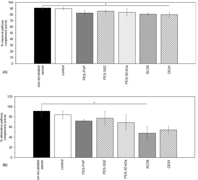
In addition to platelet adhesion, any activation of the patients’ complement system because of blood-membrane contact is an im-portant indicator of blood compatibility as well. Therefore, the average percentage of the classical and alternative pathway complement
Fig. 5. Microchip LALBA fouling results (n = 3). (A) LALBA fouling behaviour of PES-SS2 (squared data points) and PES-50 kDa (round data points) membranes at 35 μL/min (open symbols) and 130 μL/min (black symbols). (B) Macroscopic view of studied membranes in microchip: virgin PES-50 kDa membrane (left), fouled PES-SS2 membrane (centre) and fouled PES-50 kDa membrane (right).
Fig. 6. (A) Typical SEM pictures of adhered platelets on PES-PVP (A2-4), PES-SS2 (B2-4), PES-50 kDa (C2-4) membranes and glass (D2-4). Images A.1, B.1, C.1 and
D.1 show pristine materials. Surface images with magnifications of 5000× (1,3 and 4) and 1000× (2). (B) Average number of adhered platelets per cm2of material
presented for the following membranes: PES-PVP, PES-SS2 and PES-50 kDa. Error bars indicate standard deviation (n = 2, for donors 4, 5 and 6). (C) Average number of platelets present in blood. For non-incubated blood, control (incubated blood), PES-PVP, PES-SS2 and PES-50 kDa membranes. Error bars indicate standard deviation (n = 3, for donors 4, 5 and 6).
activation is shown inFig. 7. For both pathways, there is no significant difference between the complement activity of the non-incubated serum samples and the control samples (incubated serum samples), see first two bars inFig. 7. Therefore, any observed decrease in activity originates from the membrane activating the complement system via either the classical pathway, the alternative pathway or both. None of the investigated membranes is likely to activate the complement system via the classical or alternative pathway, except the DE81 and RC58
membranes ofFig. 7A and B respectively. These cellulose membranes
show a significant decrease in complement activity.
Furthermore, a thrombin generation test is used to evaluate whether or not the membrane materials trigger the coagulation of patients’ blood. If they do, the enzyme thrombin is generated and it converts, among other things fibrinogen into fibrin, the primary ingredient of a
clot [38]. A prothrombotic state is defined by (1) a short lag time,
which is the initiation phase of thrombin generation and is the time that is necessary for the generated thrombin to reach 1/6 of the peak con-centration, and (2) a high thrombin peak height, which is the rapid thrombin concentration increase in the propagation phase of thrombin
generation[38].Fig. 1A and B ofAppendix Bshow a significant
dif-ference between both the lag time and peak height of the glass samples (positive control) and the incubated PPP controls (negative control). The lag time of our PES-SS2 membranes is between the negative and
positive control. Moreover, the thrombin peak height of the PES-SS2 membranes is significantly lower than the peak height of the positive glass control, indicating that the PES-SS membranes do not activate the intrinsic coagulation pathway.
The PES-SS2 membranes performed very well in the haematology tests too. The average number of leukocytes that are present in the blood after incubation with PES-PVP, PES-SS2 and PES-50 kDa
mem-branes is comparable for all memmem-branes (seeAppendix B,Fig. 2).
Fur-thermore, the number of leukocytes present in every donors’ blood is in
the normal range (seeAppendix B, first bar inFig. 2). Moreover, the
number of leukocytes in the non-incubated blood samples and their controls, the incubated blood samples, are in similar range. This means that the well plates and rubber rings have no influence on the adhesion of the leukocytes. Finally, the results of the hemolysis test are presented
in the Table B.1. All tested membranes have an average hemolysis
percentage lower than 5% and therefore considered as non-toxic,
ac-cording to the ASTM F-756-08 standard[2]. The PES-SS2 membranes
have comparable good results for the hemolysis percentage as the benchmark PES-PVP membranes.
Overall, all the above studies show that the PES-SS2 membranes have very good blood compatibility performance and therefore are suitable for application in dialysis therapy.
Fig. 7. Average percentage classical pathway (A) and alternative pathway (B) complement activity in serum of donors 1, 2 and 3. For non-incubated serum, control (incubated serum), PES-PVP, PES-SS2, PES-50 kDa, RC58 regenerated cellulose and DE81 DEAE cellulose membranes. No significant differences in both classical and alternative pathway complement activity are observed for the different types of membranes, except for the cellulose-based membranes. Error bars indicate standard deviation (n = 2).
4. Conclusions and outlook
This study presents for the first time the successful development of low fouling, blood compatible membranes based on blends of PES and SlipSkin™. Our results show that the membranes with SS of 2 wt% (PES-SS2) have increased hydrophilicity, higher fouling resistance to pro-teins and middle-size molecules (better than benchmark membranes) and very good blood compatibility, comparable to benchmark mem-branes.
Based on the protocol for fabrication of flat-sheet PES-SS2 mem-branes (see earlier) we actually also performed preliminary studies for
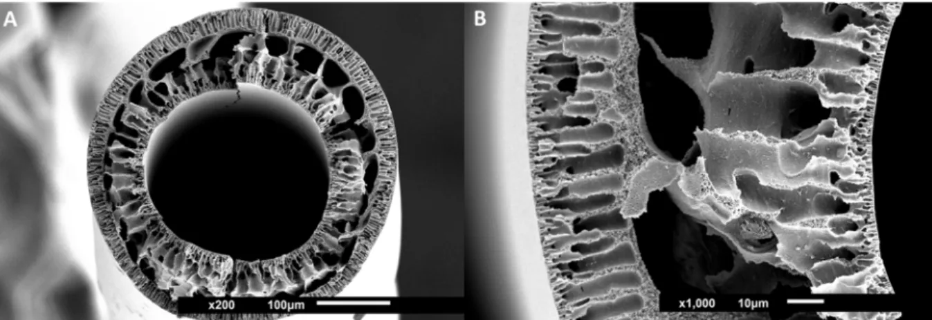
fabricating PES-SS2 hollow fiber membranes, seeFig. 8(details about
their fabrication is given in theAppendix C).
These first PES-SS2 fibers have dense inner and outer layers and in between finger- like pores and larger macrovoids. Despite that, their mechanical properties are quite good and the membranes can be
handled easily. Their clean water permeance is 7 ± 3 L m−2h−1bar−1 (measured at the TMP-range of 1–2 bar) and it is lower than that of the
PES-SS2 flat-sheet membranes (56 ± 17 L m−2h−1bar−1). Future
studies will focus on further optimization of these fibers and to the detailed investigation of their performance for filtration of uremic toxins from human plasma and full blood.
Funding
This work was supported by Health∼Holland KidneyPort [project number 40-43100-98-009]; and EU Marie Curie ITN BIOART [project number 316690].
Declaration of Competing Interest None.
Appendix A. Microfluidic chip fouling experiments A.1. Labelling of LALBA
In order to monitor the LALBA distribution and adhesion over time at zero TMP with the microchip, the proteins need to be labelled first
following the protocol of Greene et al.[31]. In short, LALBA was dissolved in sodium bicarbonate buffer to obtain a concentration of 10 mg/mL.
Subsequently, reactive dye was dissolved in 20 µL of DMSO of the labelling kit. After dissolution of both protein and corresponding dye, two mixtures were transferred into the same vial and stirred gently for 2 h. As the finishing step in the procedure, protein-dye conjugates were separated from free excess dye by gel filtration columns (size exclusion limit 5 kDa). To start the elution 5 mL of PBS was added. Solvent flow in the column was achieved by gravity only, without addition of extra pressure. The final protein concentration (mg/mL) was calculated as follows:
cprotein A280 0.05·A647·MW ·dilution factor
protein protein
=
(A.1) where A647is absorbance of the conjugate at 647 nm, A280is the absorbance of the conjugate at 280 nm, εproteinis the molar extinction coefficient of
protein (27,400 cm−1M−1) at 280 nm, MW
proteinis the molecular weight of the protein (g/mol) and the dilution factor is the dilution of the labelled conjugate prior to the absorbance measurement. A dilution factor of 10 was used in order to obtain a maximum absorbance in the range from 0.5 to 1. The absorbance of the conjugates was measured with a Libra S12 UV-spectrophotometer (Biochrom, UK). The final conjugate solution was diluted with PBS in order to achieve a concentration of 50 mg/L as it corresponds to clinically relevant median concentrations of β2-microglobulin in human
blood[35].
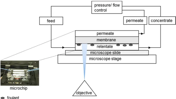
A.2. Experimental set-up
The filtration experiments were performed with two systems: (1) a Zeiss Axio Observer.zlm inverted microscope equipped with a HXP 120C power supply (Zeiss Axio Vision Software), a filter set 38 (to detect the fluorescence of α-lactalbumin-Atto-647 N), and an automated stage and (2) a Fluigent MFCS-Flex pressure controller, combined with a FLOWELL flow-controller (MAESFLO software). A total of 3 pressure and 3 flow controllers were used. Two pressure controllers can supply a pressure of up to 1000 mbar, while the other one goes up to 350 mbar. As for the flow controllers, the first one can operate at a maximum flow of 7715 μL/min, the second one at maximum flow of 55 μL/min, and the last one at a maximum flow of 1100 μL/min. The microfluidic chips were connected to the tubes of the pressure-flow controller and placed on the microscope stage to start the experimental protocol (Fig. A1).
Fig. 8. SEM images of hollow fiber PES-SS2 membranes. Images show cross-sections with magnifications of 200×, size bar 100 μm (A) and 1000×, size bar 10 μm (B), zoom-in.
Appendix B. Biocompatibility tests B.1. Coagulation - thrombin generation
Here, the intrinsic coagulation pathway is studied, because thrombin formation is triggered with phospholipids and calcium ions in this test, rather than with tissue factor[2].Fig. B1A and B show the thrombin lag time and peak height of the different samples, respectively.
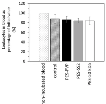
B.2. Hematology - leukocyte adhesion and hemolysis
Fig. B2shows the average number of leukocytes (as percentage of initial value) that are present in the blood after incubation with PVP, PES-SS2 and PES-50 kDa membranes. In general, the adhesion of leukocytes to the PES-PES-SS2 membranes is comparable to the PES-PVP membranes.
Table B.1presents the average hemolysis percentage of the membranes and controls. The well-plate has little effect on the average hemolysis percentage, as shown by the non-incubated and incubated blood samples (Table B.1). More importantly, the average hemolysis percentage of all
membranes is lower than 5%, indicating their non-toxicity[2].
Fig. A1. Schematic representation of the experimental set-up used combining the fluorescent microscope and the microchip.
Table B1
Average percentage hemolysis (%) ± standard deviation (n = 2 of donors 7, 8 and 9).
Membrane Hemolysis (%)
Non-incubated sample 0.01 ± 0.01
Control (incubated blood) 0.09 ± 0.03
PES-PVP 1.01 ± 0.17
PES-SS2 0.96 ± 0.17
Fig. B1. (A) Lag time in minutes and (B) peak height in nM of thrombin generation for control (incubated platelet poor plasma), PES-PVP, PES-SS2, PES-50 kDa membranes and glass (n = 3).
Fig. B2. Average number of leukocytes present in blood as percentage of initial value (%). For non-incubated blood, control (incubated blood), PES-PVP, PES-SS2 and PES-50 kDa membranes for donors 4, 5 and 6. Error bars indicate standard deviation (n = 3).
PES-SS2 hollow fiber membranes were prepared by dry-wet spinning via immersion precipitation. First, 15 wt% PES was dissolved in NMP and then 2 wt% SS was added. The polymer solution was mixed on a rollerbank for at least 48 h and degassed for 24 h before the spinning process.
The polymer solutions were pumped through the spinneret using a speed of 1 mL/min at room temperature (the dimensions of the spinneret are
listed inTable C1below). To create the bore, ultrapure water was pumped through the spinneret with a speed of 5.8 mL/min. After an airgap of
10 cm between the spinneret and the ultrapure water - coagulation bath, the fiber was collected using a pulling wheel with a speed of 18.6 m/min.
Appendix D. Supplementary material
Supplementary data to this article can be found online athttps://doi.org/10.1016/j.seppur.2019.05.049.
References
[1] M.S.L. Tijink, et al., Mixed matrix hollow fiber membranes for removal of protein-bound toxins from human plasma, Biomaterials 34 (32) (2013) 7819–7828. [2] M. Tijink, et al., Development of novel membranes for blood purification therapies
based on copolymers of N-vinylpyrrolidone and n-butylmethacrylate, J. Mater. Chem. B 1 (44) (2013) 6066–6077.
[3] R. Vanholder, et al., Review on uremic toxins: classification, concentration, and interindividual variability, Kidney Int. 63 (5) (2003) 1934–1943.
[4] A. Davenport, Portable and wearable dialysis devices for the treatment of patients with end-stage kidney failure: Wishful thinking or just over the horizon? Pediat. Nephrol. 30 (12) (2014) 2053–2060.
[5] A. Davenport, et al., A wearable haemodialysis device for patients with end-stage renal failure: a pilot study, Lancet 370 (9604) (2007) 2005–2010.
[6] W.H. Fissell, S. Roy, A. Davenport, Achieving more frequent and longer dialysis for the majority: wearable dialysis and implantable artificial kidney devices, Kidney Int. 84 (2) (2013) 256–264.
[7] S. Eloot, I. Ledebo, R.A. Ward, Extracorporeal removal of uremic toxins: can we still do better? Semin. Nephrol. 34 (2) (2014) 209–227.
[8] V. Gura, et al., Continuous renal replacement therapy for endstage renal disease -The wearable artificial kidney (WAK), Cardiovasc. Disorders Hemodial. 149 (2005) 325–333.
[9] H. Susanto, M. Ulbricht, Characteristics, performance and stability of poly-ethersulfone ultrafiltration membranes prepared by phase separation method using different macromolecular additives, J. Membr. Sci. 327 (1–2) (2009) 125–135. [10] M. Teodorescu, M. Bercea, Poly(vinylpyrrolidone) - a versatile polymer for bio-medical and beyond bio-medical applications, Polym.-Plast. Technol. Eng. 54 (9) (2015) 923–943.
[11] S.Q. Nie, et al., Improved blood compatibility of polyethersulfone membrane with a hydrophilic and anionic surface, Colloids Surfaces B-Biointerfaces 100 (2012) 116–125.
[12] Y.L. Su, et al., Modification of polyethersulfone ultrafiltration membranes with phosphorylcholine copolymer can remarkably improve the antifouling and per-meation properties, J. Membr. Sci. 322 (1) (2008) 171–177.
[13] Y. Koga, et al., Biocompatibility of polysulfone hemodialysis membranes and its mechanisms: involvement of fibrinogen and its integrin receptors in activation of platelets and neutrophils, Artif. Organs 42 (9) (2018) E246–E258.
[14] M. Matsuda, et al., Effects of fluid flow on elution of hydrophilic modifier from dialysis membrane surfaces, J. Artif. Organs 11 (3) (2008) 148–155.
[15] K. Namekawa, et al., Poly(N-vinyl-2-pyrrolidone) elution from polysulfone dialysis membranes by varying solvent and wall shear stress, J. Artif. Organs 15 (2) (2012) 185–192.
[16] B. Madsen, et al., Effect of sterilization techniques on the physicochemical prop-erties of polysulfone hollow fibers, J. Appl. Polym. Sci. 119 (6) (2011) 3429–3436. [17] W. Albrecht, et al., Modification of poly(ether imide) membranes with brominated
polyvinylpyrrolidone, J. Membr. Sci. 291 (1–2) (2007) 10–18.
[18] M. Miyata, et al., Influence of sterilization and storage period on elution of poly-vinylpyrrolidone from wet-type polysulfone membrane dialyzers, Asaio J. 61 (4) (2015) 468–473.
[19] K. Namekawa, et al., Longer storage of dialyzers increases elution of poly(N-vinyl-2-pyrrolidone) from polysulfone-group dialysis membranes, J. Artif. Organs 14 (1) (2011) 52–57.
[20] X.L. Liu, et al., Poly(N-vinylpyrrolidone)-modified surfaces for biomedical appli-cations, Macromol. Biosci. 13 (2) (2013) 147–154.
[21] S. Konishi, et al., Eluted substances from hemodialysis membranes elicit positive skin prick tests in bioincompatible patients, Artif. Organs 39 (4) (2015) 343–351. [22] N. Nady, et al., Modification methods for poly(arylsulfone) membranes: A
mini-review focusing on surface modification, Desalination 275 (1–3) (2011) 1–9. [23] C. He, et al., Graphene oxide and sulfonated polyanion co-doped hydrogel films for
dual-layered membranes with superior hemocompatibility and antibacterial ac-tivity, Biomater. Sci. 4 (10) (2016) 1431–1440.
[24] C.X. Nie, et al., Novel heparin-mimicking polymer brush grafted carbon nanotube/ PES composite membranes for safe and efficient blood purification, J. Membr. Sci. 475 (2015) 455–468.
[25] H.H.L. Hanssen, et al., Metallic wires with an adherent lubricious and blood-com-patible polymeric coating and their use in the manufacture of novel slippery-when-wet guidewires: Possible applications related to controlled local drug delivery, J. Biomed. Mater. Res. 48 (6) (1999) 820–828.
[26] C.C.L. Peerlings, et al., Heparin release from slippery-when-wet guide wires for intravascular use, J. Biomed. Mater. Res. 63 (6) (2002) 692–698.
[27] R.T. Pijls, et al., Flexible coils with a drug-releasing hydrophilic coating: A new platform for controlled delivery of drugs to the eye? Bio-Med. Mater. Eng. 14 (4) (2004) 383–393.
[28] Y.A. Liu, et al., Improved antifouling properties of polyethersulfone membrane by blending the amphiphilic surface modifier with crosslinked hydrophobic segments, J. Membr. Sci. 486 (2015) 195–206.
[29] D. Pavlenko, et al., New low-flux mixed matrix membranes that offer superior re-moval of protein-bound toxins from human plasma, Sci. Rep. 6 (2016) 34429. [30] ISO, ISO 10993-4:2002/Amd 1:2006 - ICS : 11.100.20 Biological evaluation of
medical devices, 2006(1).
[31] L.H. Greene, et al., Stability, activity and flexibility in alpha-lactalbumin, Protein Eng. 12 (7) (1999) 581–587.
[32] S.V. Kumar, et al., N-vinylpyrrolidone and ethoxyethyl methacrylate copolymer: Synthesis, characterization and reactivity ratios, J. Macromol. Sci. Part a-Pure Appl. Chem. 44 (10–12) (2007) 1161–1169.
[33] H.M. Song, et al., Hemocompatibility and ultrafiltration performance of surface-functionalized polyethersulfone membrane by blending comb-like amphiphilic block copolymer, J. Membr. Sci. 471 (2014) 319–327.
[34] S. Eloot, Experimental and Numerical Modeling of Dialysis, PhD dissertation Ghent University, 2004.
[35] M. Meireles, P. Aimar, V. Sanchez, Albumin denaturation during ultrafiltration -effects of operating-conditions and consequences on membrane fouling, Biotechnol. Bioeng. 38 (5) (1991) 528–534.
[36] S.H. Yun, et al., Platelet activation: the mechanisms and potential biomarkers, Biomed. Res. Int. (2016).
[37] E.L.G. Pryzdial, et al., Blood coagulation dissected, Transfus. Apheres. Sci. 57 (4) (2018) 449–457.
[38] E. Castoldi, J. Rosing, Thrombin generation tests, Thromb. Res. 127 (2011) S21–S25.
Table C1
Fabrication conditions of the PES-SS2 hollow fiber membranes.
Spinning parameters PES-SS2
Inner diameter needle of spinneret 0.2 mm
Outer diameter needle of spinneret –
Inner diameter first orifice of spinneret 0.5 mm Outer diameter first orifice of spinneret 0.8 mm Inner diameter second orifice of spinneret 1 mm
Polymer dope pumping speed 1.0 mL/min
Bore liquid pumping speed 5.8 mL/min
Air gap 10 cm
Pulling wheel speed 18.6 m/min