HAL Id: hal-02418118
https://hal.archives-ouvertes.fr/hal-02418118
Submitted on 18 Dec 2019
HAL is a multi-disciplinary open access
archive for the deposit and dissemination of
sci-entific research documents, whether they are
pub-lished or not. The documents may come from
teaching and research institutions in France or
abroad, or from public or private research centers.
L’archive ouverte pluridisciplinaire HAL, est
destinée au dépôt et à la diffusion de documents
scientifiques de niveau recherche, publiés ou non,
émanant des établissements d’enseignement et de
recherche français ou étrangers, des laboratoires
publics ou privés.
fuel debris simulants for the development and
qualification of laser cutting technique
Christophe Journeau, J. Monerris, B. Tormos, L. Brissonneau, E. Excoffier, V.
Testud, C. Chagnot, D. Roulet
To cite this version:
Christophe Journeau, J. Monerris, B. Tormos, L. Brissonneau, E. Excoffier, et al..
Fabricating
Fukushima Daiichi in-vessel and ex-vessel fuel debris simulants for the development and
qualification of laser cutting technique. The 8th European Review Meeting on Severe Accident Research
-ERMSAR-2017, May 2017, Varsovie, Poland. �hal-02418118�
*
Corresponding author
Email address: christophe.journeau@cea.fr (C. Journeau)
simulants for the development and qualification of laser cutting technique
Christophe Journeau
a, José Monerris
a, Brigitte Tormos
a, Laurent Brissonneau
a,
Emmanuel Excoffier
b, Véronique Testud
b, Christophe Chagnot
c, Damien Roulet
da Commissariat à l’Energie Atomique et aux Energies Alternatives (CEA), Cadarache,
13108 Saint-Paul-lez-Durance, France
b
Commissariat à l’Energie Atomique et aux Energies Alternatives (CEA), Marcoule, 30207 Bagnols/Cèze, France
c
Commissariat à l’Energie Atomique et aux Energies Alternatives (CEA), Saclay, 91191 Gif sur Yvette, France
d
ONET Technologies, 26701 Pierrelatte, France
Abstract
In their roadmap towards the decommissioning of Fukushima Daiichi reactors, the Japanese authorities plan to start removing fuel debris by the end of 2021. To reach this objective, several R&D projects have been launched and subsidized by the Japanese government. In this framework, a French consortium (COMEX Nucléaire/ONET Technologies, CEA and IRSN) has been selected to implement R&D related to the laser cutting of Fukushima Daiichi fuel debris and related dust collection technology.
Some of the key aspects of this project are to fabricate representative corium debris simulants, to test laser cutting technique on these simulants and to measure the aerosols and dusts that are released during the debris thermal cutting. This paper concentrates on the first issue.
Two representative corium compositions have been selected: in-vessel debris having the average of Fukushima Daiichi Unit 2 (1F2) lower head debris composition best estimates from the OECD Benchmark Study of the Accident at the Fukushima Daiichi Nuclear Power Station (BSAF); ex-vessel debris composition chosen from DOE calculations on Fukushima Daiichi Unit 1 (1F1) molten core concrete interaction in order to maximize the concrete content and bound the possible composition space.
Fission Products expected 10 years after plant shutdown have also been taken into account. As it was not possible within the current project timeframe to perform debris cutting tests with (depleted) uranium oxide, it has been necessary to simulate uranium oxide and hafnium oxide has been considered as the best option.
Based on its 20 year experience in corium experimental R&D, PLINIUS platform at CEA Cadarache has been chosen to fabricate these simulants. Two blocks of 8-10 kg have been induction melted. After melting and cooling, samples have been analyzed (microstructure and chemical composition) and laser cutting of these simulant blocks has been successfully carried out.
Keywords: Fukushima Daiichi accident, In-Vessel Corium, Ex-Vessel Corium, Corium Simulants.
1. Introduction
In their roadmap towards the decommissioning of Fukushima Daiichi (1F) reactors [1], the Japanese authorities plan to start removing fuel debris by the end of 2021. To reach this objective, the fuel debris retrieval methods for the first implementing unit shall be selected during Japanese Fiscal year 2018. Cutting fuel debris (corium) is an important issue and several R&D projects have therefore been launched and subsidized by the Japanese government to study potential techniques. In this framework, a French consortium (COMEX Nucléaire / ONET Technologies, CEA and IRSN) has been selected to implement R&D related to the laser cutting of 1F fuel debris and related dust collection technology.
Laser technology dates back to the 60’s. It has been used for industry applications for almost as long, and the feasibility of cutting applications was quickly demonstrated. In recent years, with the help of high-power lasers, this technology of laser-cutting has started to be applied to the extreme environments that can be found in nuclear facilities, especially in the case of nuclear decommissioning [2][3], where remote operations are often mandatory.
Ex-vessel corium interactions and coolability - Paper N° 204
Asides from experimental optimization of the laser-cutting technique on commercially-available samples such as electrofused zirconia, steel and zirconium plates, one specificity of our approach is to have specifically fabricated simulant of Fukushima-Daiichi fuel debris that have in a second part been subjected to laser cutting in our facility while aerosol production has been analyzed.
This paper concentrates on the fabrication of representative samples. In a first section, the selection of two representative debris compositions, one for in-vessel corium, one for ex-vessel corium will be presented. Then the fabrication of the two simulant blocks will be described followed by material analyses, with a focus on the ex-vessel fuel debris simulant block. Finally, some information will be provided on their laser cutting.
2. Definition of debris simulant compositions
The objective of the debris simulant is to reproduce as far as possible typical conditions that are expected in the dismantling of Fukushima Daiichi debris with respect to laser cutting and aerosol production. Therefore, it is necessary to be as close as possible to typical compositions that are expected for 1F molten fuel debris: oxide component, metallic phase, non-volatilized fission products.
As appropriate room for the laser cutting and aerosol sampling of radioactive prototypic corium samples with depleted uranium was not available during the current phase of the project, it has been decided to utilize a simulant material. Hafnium has been considered as surrogate for uranium as the thermal properties of hafnium and uranium oxides are quite close [4]: melting points at respectively 3063 and 3033 K; thermal conductivities in solid state at close to 2 W.m-1.K-1 in the solid state and the heat of fusions are of the order of 100 ± 30 kJ/kg for both oxides; specific densities at room temperatures of 9 680 and 10 500 kg/m3. Nevertheless, uranium has 4 oxidation states (+3, +4, +5, +6) leading to the formation of 4 gaseous species in the U-O system (U, UO, UO2,
UO3) two of which are quite volatile, while hafnium presents only the +4 oxidation state.
No known simulant can represent this complex chemistry [5]. Uranium isotopes contribute only to 7 millionths of the debris total radioactivity, as estimated for 10 years after the accident [6], so it will contribute to a very small fraction of the aerosol radioactivity, but it will nevertheless be a major part of the aerosol mass. Therefore the volatilization of uranium compound cannot be represented by our simulant whereas the thermal cutting can be satisfactorily appreciated.
2.1. Fission products
Figure 1 Repartition of 1F1 core radioactivity, 10 years after accident (from [6] data)
CS137 21,6% BA137M 20,4% PU241 18,5% Y90 15,8% SR90 15,8% PM147 2,8% KR85 1,6% CS134 0,9% PU238 0,6% EU154 0,5% AM241 0,5% CM244 0,2% EU155 0,2% PU240 0,1% SB125 0,1% PU239 0,1% SM151 0,1% RH106 0,1% RU106 0,1%
Repartition of radioactivity in 1F1 core after 10 years
CS137 BA137M PU241 Y90 SR90 PM147 KR85 CS134 PU238 EU154 AM241Ex-vessel corium interactions and coolability - Paper N° 204
From JAEA published data on the isotopic composition of 1F reactor fuels [6], the core inventory 10 years after the accident is such that the isotopes with the largest radioactivity are (Figure 1): Caesium 137 (which as a volatile fission product must be largely out of the fuel debris), Barium 137 (the daughter of caesium-137, which must have similarly been largely released), Plutonium 241 (a low volatile with only 1 to a few percent release; ), Yttrium 90 (the daughter of strontium-90, another low volatile) and Strontium 90 (a low volatile). The repartition of masses is somewhat different due to the different half-lives and atomic masses. No major differences have been obtained between the 3 damaged plants in terms of isotopic composition 10 years after accident.
2.2. In-vessel fuel debris
Pellegrini et al. [7] have reported the debris compositions obtained by various teams on the benchmark on Fukushima Daiichi accident calculations organized by OECD/NEA (BSAF project). For the unit 2 lower head debris (Figure 4), the average between the lower head debris bed calculated by CIEMAT, CRIEPI, IAE and IBRAE is approximately:
37 wt% UO2, 37 % Zr, 16% ZrO2, 6% Stainless Steel, 3% Steel oxides, 1% B4C.
This correspond to an oxidation ratio of zirconium of C241. This composition has been processed to include the largest minor elements taking into account the knowledge of 1F2 inventory (fission products, transuranians, etc.) as given by the compilation of Nishiara et al. [6]. The Stainless Steel has been considered as 304L steel.
Uranium has been replaced mole by mole by hafnium in the chosen simulants. Cerium has been chosen to simulate plutonium. For the fission products, natural isotopic composition are used instead of the isotopic composition to be found in reactor. This will allow for the same thermochemistry and aerosol properties while enabling experimentation outside of a hot laboratory, but it is less favorable for detection.
All elements corresponding to more than 0.01 wt% of the calculated debris composition have been considered, except Technetium which has no stable isotope and ruthenium which raises a health issue for workers in oxidic environment (this issue is negligible in presence of radioactive isotope where protective measures are anyhow taken). Altogether, more than 95% of the expected radioactivity after 10 years is simulated in the composition presneted in Table 1.
Table 1 In-vessel simulant designed composition (in g per 10 kg) HfO2 3 019.29 SiO2 19.35 Zr 3 789.99 MoO2 9.37 ZrO2 1 983.70 Cs2O 6.64 Fe 619.90 Ba 4.29 Cr 177.19 La2O3 3.52 B4C 109.48 PdO 3.30 Ni 102.16 Pr2O3 3.30 SnO2 99.25 Sr 2.04 CeO2 19.17 Sm2O3 1.61 MnO 11.68 Y2O3 1.56 Nd2O3 11.71 TeO2 1.50
2.3. Ex-vessel fuel debris
In order to represent one typical Molten Core Concrete Interaction (MCCI) debris composition, we have considered the published works of Robb et al. [9] which modelled spreading and MCCI in Fukushima Daiichi unit 1 (1F1). They have considered several cases corresponding to different code calculations of the in-vessel breach. We have selected the MAAP calculation for the low pressure case (actually the high pressure case gives similar values). This has been made in such a way that the ex-vessel sample is considered with the maximum average concrete content from the surveyed configuration while the in-vessel sample has indeed 0% concrete. This correspond to a maximum fraction of 54 wt% concrete, assuming there was no mixing between the sump
1
Molar ratio of oxidized zirconium to total amount of zirconium: C24 means than 24 mol% of zirconium have been fully oxidized to +4 state.
Ex-vessel corium interactions and coolability - Paper N° 204
(where most MCCI is considered to have occurred) and the remainder of the corium spread (for which a lower fraction of concrete has been calculated) and that the densities of corium and concrete are respectively of 8000 and 2100 kg.m-3. Considering SURC experimental program [10] published composition for basaltic concrete and the fraction of iron reinforcement bars used in MOCKA experiments [11], and applying the same substitutions as for the in-vessel case, Table 2 presents the selected composition for the ex-vessel fuel debris simulant.
Table 2 Ex-vessel simulant designed composition (in g per 10 kg) For 10 000 g wt% For 10 000 g wt% HfO2 2 036.62 g 20.366% Fe2O3 286.37 g 2.864% CeO2 18.47 g 0.185% Nd2O3 8.93 g 0.089% ZrO2 1 240.32 g 12.403% MoO2 8.46 g 0.085% SnO 15.80 g 0.158% Cs2O 5.04 g 0.050% B4C 17.36 g 0.174% Ba 3.33 g 0.033% Cr2O3 58.11 g 0.581% La2O3 2.66 g 0.027% Fe 630.09 g 6.301% PdO 2.55 g 0.026% FeO 1 177.76 g 11.778% Pr2O3 2.45 g 0.024% Ni 52.04 g 0.520% Sm2O3 1.83 g 0.018% SiO2 3 039.51 g 30.395% Sr 1.47 g 0.015% Al2O3 758.62 g 7.586% Y2O3 1.15 g 0.012%
3. Debris simulant blocks fabrication and analyses
3.1. Ex-vessel fuel debris simulant
3.2.
4.
Figure 2 Experimental induction melting set-up
An Ex-Vessel (Molten Core Concrete Interaction) fuel debris simulant block has been fabricated at CEA Cadarache PLINIUS experimental platform on April 19th, 2016. About 10 kg of the load described in Table 2 have been inserted inside a Ø 180 mm x 290 mm-high (inner dimensions) magnesium-stabilized-zirconia (Zircoa 3001) crucible. The crucible is surrounded by a copper induction coil protected by oxidic powder (Erreur !
Source du renvoi introuvable.). Power has been initially induced to the steel balls using PLINIUS platform
new induction generator. The load temperature progressively increased, leading to progressive melting of the load (Figure 3 left) and induction coupling to the oxide melt pool. When high temperatures (around 2000°C) have been reached, partial volatilization of some compounds occurred (Figure 3 center) as during a severe accident. Due to the important reduction of porosity between powder and melt, a cavity was formed above the
Crucible filled by powders
Nitrogen inflow
Aspiration to filters
Ex-vessel corium interactions and coolability - Paper N° 204
melt and below a partly sintered upper crust (Figure 3 right). Material from this crust progressively sank inside the melt. Then, the heating has been terminated and the fuel debris cooled. After removal of the remaining powder and of projections, about 8 kg of fuel debris simulant have been fabricated.
The high efficiency filter collecting aerosols has been weighed before and after the test. Less than 0.5 g of aerosols has been collected. The VF-03 filter has been transferred to CEA Cadarache LIPC material analysis laboratory and the collected aerosols have been examined with a ZEISS EVO HD15MA Scanning Electron Microscope (LaB6 gun) equipped with an OXFORD SDD X-Max 50 Energy Dispersive Spectrosopy detector for
chemical analysis.
Figure 3: Three steps of Ex-vessel 1F1 Fuel debris fabrication
Left: start of melting phase – Center: Melting and aerosol release – Right: Cooling phase
The micrographs presented in this report are made with backscattered electrons (BSE). The grey levels mainly indicate composition differences: the higher is the density in heavier elements (high Z: Zr, Hf…) in a zone, the lighter it appears on the micrograph. The INCA software (Oxford Instrument) is used to process and analyze EDS spectra. An uncertainty of ±1/10th of the measured concentration must be considered for each element.
Deposits on the filter fibers and some powder composed of small particles (less than 0.2 µm) or small droplets (0.5 to 5 µm diameter, Figure 4) can be observed.
Figure 4: Small droplets in the powder. Note that very small droplets appear at the surface of bigger ones (the lighter-colored is a droplet, the more it contains the heavy elements Sn, Te, Cs).
Ex-vessel corium interactions and coolability - Paper N° 204
The composition of the powder or of the droplets is very similar to the one of the deposits: the elements which are mainly and simultaneously detected are Si, Sn, Te, Cs, Cr, Fe, Ni and O (see Erreur ! Source du
renvoi introuvable.), sometimes with C, Al, Pd and Mo.
Table 3 Volatilization of Ex-vessel simulant fuel debris during fabrication stage Element Load
wt.%
Volatilization class[12]
Volatilization during melting
Hf 25.5% Non volatile Present in few droplets. Limited evaporation Fe 23.1% Semi volatile [13] One of the main elements of aerosols. Si 21.0% Semi volatile One of the main elements of aerosols. Zr 13.6% Non volatile Present in few droplets.
Ca 6.5% Semi volatile [13] Present in few droplets. Al 5.9% Low volatile [13] Detected in some aerosols
Cr 2.03% Semi volatile [13] One of the main elements of aerosols. Ni 1.07% Semi volatile [13] One of the main elements of aerosols. Mo2 0.30%
Semi-volatile Detected in some aerosols. About 80-90% of the initial molybdenum has been released
Ce 0.22% Low volatile Not detected B 0.20% Semi volatile [13] Not detectable Sn 0.18%
Not described One of the main elements of aerosols (as e.g. in Phébus FPT3 [14]) Nd 0.11% Non volatile Not detected
Cs 0.07%
Volatile One of the main elements of aerosols. About 50% depletion from melt
Ba 0.05% Semi-volatile Not detected La 0.034% Low volatile Not detected Pr 0.033% Non volatile Not detected
Pd 0.031% Semi-volatile Detected in some aerosols Sm 0.024% Not described Not detected
Sr 0.023% Low volatile Not detected Te 0.014%
Volatile One of the main elements of aerosols. Around 90% of the original tellurium has been released
Y 0.013% Low volatile Not detected
Some droplets of slightly larger size might have different compositions: Si-Fe-Cr-O. A few larger droplets (25-50 µm diameters) were observed which are likely to have escaped in liquid state from the molten pool. They contain: Si, Zr, Hf, Ca, Fe, Cr, Ni, O. Small peaks of Te, Cs and Sn are detected on these droplets. Large plates (>100µm) contains Si, K, Mg, Na, Al, Ti, O, Fe and a few rare blocks of ZrO2 (>50 µm) and HfO2 (>20 µm) can
also be found.
Due to the collected mass of aerosols (<0.5 g in filter), it is unlikely that any element totally volatized from the debris. From the analysis of the filter samples, the following evaporation behavior of simulant debris elements has been observed during the heating phase (somewhat simulating the volatilization during severe accident) and listed in Erreur ! Source du renvoi introuvable.. It corresponds well to the volatilization classes established for severe accident conditions in [12].
In order to keep a large block for laser cutting, samples have been taken from the periphery of the fuel debris simulant block in a first stage. One oxidic sample (from splashes above the free surface) and one metallic sample (from below) have been analyzed. A second series of analyses from the block center, has been carried out after it has been laser cut.
The samples have been transferred to CEA Marcoule LMAC laboratory, separated in several subsamples and then crushed in an inert mortar. Three dissolution techniques have been used: solubilization in HNO3
-HCl-HF mixtures, acid solubilization under pressure in microwave furnace, solubilization using an alkaline flux. 98 to 100% dissolution has been obtained depending on the technique.
2
Ex-vessel corium interactions and coolability - Paper N° 204 Table 4 tentative composition (wt.%) of the two phases after fabrication process
Element Oxide (periphery)
Oxide (core)
Metallic part O 24 % Not determined Not determined
Hf 21% 13% Si 17% 11% Fe 14% 9% 81% Zr 11% 20% Ca 5% 3.2% Al 4% 3.3% Cr 2% 1.0% 0.8% Ce 0.2% 0.15% B 0.2% 0.01% Nd 0.9% 0.06% Sn 0.4% 0.06% 0.2% Ni 0.03% 0.25% 14% Cs 0.03% 0.03% La 0.02% 0.02% Pr 0.02% 0.02% 0.3-0.7% Sm 0.02% 0.014% Sr 0.02% 0.015% Y 0.01% 0.025% Mo 0.01% 0.031% 0.4% Pd 0.01% 0.005% Te 0.002% <0.002% 0.015%
A tentative composition (in wt.%) for the debris can be proposed for the oxidic part (main phase of the debris) as well as for the metallic part, taking into account the initial load inventory, the measured sample compositions and the releases. It is listed in Table 4.
It occurs that the core composition is somewhat different with that of the periphery (which may not have completely been mixed and which has been less subject to volatilization, being rapidly solidified). Considering the inner core composition (which is the average of 7 subsample analyses) and the aerosol collection during the melting phase, release fractions during fabrication have been assumed in order to fit the observations and analyses for each element (except for palladium) and are presented in Table 5.
Table 5 Assumed released fractions during fabrication process
Element Hf Fe Si Zr Ca Al Cr Ni Mo Ce B 0.01% 0.2% 0.2% 0.01% 0.01% 0.1% 2% 2% 10% 0.01% 20% Element Sn Nd Cs Ba La Pr Pd Sm Sr Te Y
30% 0% 40% 1% 20% 35% ? 0 0 90% 0
4.1. In-vessel fuel debris simulant
Similarly, more than 10 kg In-Vessel fuel debris simulant has been fabricated at CEA Cadarache PLINIUS experimental platform during test VF-04 on April 28th, 2016 using a similar procedure as for the ex-sample. The major difference was that argon was blown above the test section instead of nitrogen. Figure 5 left presents the fabricated block.
Ex-vessel corium interactions and coolability - Paper N° 204
Figure 5: Left: Top-view of the in-vessel fuel debris simulant Right: sample for analysis
A sample has been taken from the fuel debris simulant block periphery (Figure 5 right). The same analysis procedure has been applied at LMAC laboratory in CEA Marcoule than for the ex-vessel oxidic samples. The averaged results of the analyses of 4 sub-samples dissolved with microwave furnace solubilization are reported in Table 6. Solubilization using an alkaline flux has also been used for confirmation (but is not reported here as some elements cannot be analyzed since they are also present in the alkaline flux). The uncertainty is estimated at 10% of the reported values. Similarly, a sample from the core of the block has been analyzed after laser cutting (Table 7).
The analysis of the debris sample shows that some of the major elements fractions are quite different from the initial composition. This is likely to be a consequence of the separation of VF04 melt in two liquids, an oxidic melt and a metallic melt, while only the oxidic melt has been found at the surface. No stratified melt has been found when the block has been cut, but it seems that different phases must have been present since the composition varied a lot from a sub-sample to the other. The fact that the highest standard deviations correspond to the metallic phase elements (Fe, Cr, Ni, Sn, Mo, Te) support this hypothesis. Further works are needed to better characterize this heterogeneous in-vessel block.
Table 6: Averaged measured composition of in-vessel oxidic sample (periphery)
Elements Zr Hf Sn B Fe Ce Nd Mo Cr Pd La
wt.% 44 31 1.3 1.2 0.40 0.30 0.11 0.11 0.046 0.042 0.031
Elements Al Ni Pr Sr Y Sm Te Si Ca Ba Cs
Wt.% 0.030 0.027 0.018 0.016 0.017 0.015 0.0049 <0.06 <0.06 <0.002 <0.002
Table 7: Averaged measured composition of in-vessel oxidic sample (core of block)
Elements Zr Hf Sn B Fe Ce Nd Mo Cr Pd La
wt.% 46 17 0.2 0.1 9.1 0.14 0.1 0.02 1.6 0.004 0.026
Elements Al Ni Pr Sr Y Sm Te Mg Ca Ba Cs
Ex-vessel corium interactions and coolability - Paper N° 204
5. Debris simulant blocks laser cutting
Laser-cutting has been performed in air at CEA CELENA laser shot unit of the ALTEA platform. A Trumpf 8002-type 1030-nm laser souce with continuous power of 8 kW is connected by optical fibers to CEA laser head positioned on a PRIME 3-axis robot. Two comporessed air jet flows are provided, one around the laser head and one at 45° from the corium surface (Figure 6).
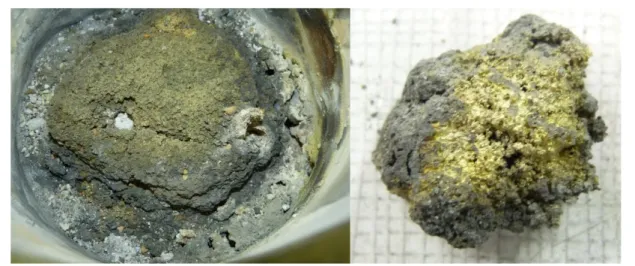
Figure 6: Ex-vessel corium simulant in the CELENA laser shot unit
The laser head has been moved at a speed of 15 cm/min and the two corium simulant blocks have been both cut to a depth of approximately 40 mm (Figure 7). The grooves are clear and clean and little adhesive scoria accumulates at their sides, so that the resulting corium-head distance is relatively unaffected. From the collection of aerosols and dross, it is estimated that about 10 g are ejected far of the block when 1 meter of corium is being laser cut.
Figure 7: Cut In-vessel (left) and Ex-vessel (right) corium simulant blocks. Ex-vessel
simulant block
Auxiliary jet flushing nozzle
Laser head and protection nozzle
Ex-vessel corium interactions and coolability - Paper N° 204
6. Conclusions and perspectives
Two representative corium compositions have been selected: in-vessel debris having the average of Fukushima Daiichi Unit 2 (1F2) lower head debris composition best estimates from the OECD Benchmark Study of the Accident at the Fukushima Daiichi Nuclear Power Station (BSAF); ex-vessel debris composition chosen from DOE calculations on Fukushima Daiichi Unit 1 (1F1) molten core concrete interaction in order to maximize the concrete content and bound the possible composition space. Fission Products expected 10 years after plant shutdown have also been taken into account. As it was not possible within the current project timeframe to perform debris cutting tests with (depleted) uranium oxide, it has been necessary to simulate uranium oxide and hafnium oxide has been considered as the best option.
Two blocks of 8-10 kg have been induction melted. After melting and cooling, samples have been analyzed (microstructure and chemical composition) and laser cutting of these simulant blocks has been successfully carried out.
At the time of writing, these corium simulant blocks are being laser cut in air and underwater while released aerosols are being measured and sampled. Further material analyses are also ongoing. Nevertheless current analyses have indicated that the found collected aerosols correspond well to the volatilization classes established for severe accident conditions.
In a further stage, it is proposed to fabricate prototypic fuel debris including depleted uranium and ruthenium and to laser cut them in a specifically adapted space at CEA, in order to improve the representativity of the laser cutting tests with respect to the release of volatiles.
This experimental R&D is aiming at industrial application on site if requested by Fukushima Daiichi fuel debris retrieval strategy that will soon be decided by the Japanese authorities.
Acknowledgements
This subsidized project is funded by the Japanese Ministry of Economy, Trade and Industry (METI) through the Eco Future Fund (EFF) and managed by the Mitsubishi Research Institute (MRI).
The help of Nicolas Bouchilloux, Patricia Correggio, Romuald Malet, Diego Molina, Pascal Piluso, Christophe Suteau and Béatrice Teisseire is gratefully acknowledged.
References
[1] Inter-Ministerial Council for Contaminated Water and Decommissioning Issues, Mid-and-Long-Term Roadmap towards the Decommissioning of TEPCO’s Fukushima Daiichi Nuclear Power Station, METI, Tokyo, June 12, 2015.
[2] J.P. Alfille and G. Pilot, Thick cutting of metallic material for nuclear dismantling applications with pulsed YAG laser, Proceedings of ICONE 5, 5th International Conference on Nuclear Engineering, Nice, May 26–30 1997.
[3] C. Chagnot, G. de Dinechin, G. Canneau, Cutting performances with new industrial continuous wave Nd:YAG high power lasers: For dismantling of former nuclear workshops, the performances of recently introduced high power continuous wave Nd:YAG lasers are assessed, Nucl. Eng. Des. 240, pp. 2604-2613, 2010.
[4] G.V. Samsonov, The oxide handbook, IFI/PLENUM, New York, 1973.
[5] C. Journeau, L. Buffe, J.F. Haquet, P. Piluso, G. Willermoz, Needs for large mass prototypic corium experiments ; the PLINIUS2 platform, NURETH-16, Chicago, IL, 2015.
[6] K. Nishihara, H. Iwamoto, K. Suyama, Estimation of Fuel Compositions in Fukushima-Daiichi Nuclear
Power Plant, JAEA Report JAEA-Data/Code 2012-018, 2012.
[7] M. Pellegrini, K. Dolganov, L. E. Herranz Puebla, H. Bonneville, D. Luxat, M. Sonnenkalb, J. Ishikawa, J. H. Song, R. O. Gauntt, L. Fernandez Moguel, F. Payot,Y. Nishi, Benchmark Study of the Accident at the Fukushima Daiichi NPS Best Estimate Case Comparison, NURETH 16, Chicago, IL, 2015.
[8] L. Capriotti, A. Quaini, R. Böhler, K. Boboridis, L. Luzzi, D. Manara, A laser heating study of the CeO2 solid/liquid transition: challenges related to a refractory compound with a very high oxygen pressure, High Temperatures-High Pressures 44, pp. 69-82, 2014.
Ex-vessel corium interactions and coolability - Paper N° 204
[9] K. Robb, M.W. Francis, M. T. Farmer, Ex-Vessel Core Melt Modeling Comparison between
MELTSPREAD-CORQUENCH and MELCOR 2.1, Oak Ridge National Lab report ORNL/TM-2014/1,
2014.
[10] E. R. Copus, R. E. Blose, J. E. Brockmann, R. B. Simpson, D. A. Lucero, Core-Concrete Interactions
Using Molten UO2 With Zirconium on a Basaltic Basemat, The SURC-2 Experiment, Sandia Nat. Lab.
Report NUREG/CR—5564, 1992.
[11] J. J. Foit, MCCI on LCS concrete with and without rebars, ERMSAR 2015, Marseille, France.
[12] G. Ducros, Y. Pontillon, P.P. Malgouyres, Synthesis of the VERCORS experimental programme: Separate effect experiments on Fission Product Release, in support of the Phébus-FP programme, Ann. Nucl. Energ. 61, pp. 75-87, 2013.
[13] H. Alsmeyer, G. Cenerino, E.H.P. Cordfunke, D. Fioravanti, M. Fischer, J.J. Foit, L.D. Howe, M.E. Huntelaar, S. Locatelli, F. Parozzi, I. Szabo, B.D. Turland, M. Vidard, D. Wegener, Molten
corium/concrete interaction and corium coolability: A state of the art report, EUR 16649 EN, European
Commission, Luxembourg, 1995.
[14] T. Haste, F. Payot, C. Manenc, B. Clément, P. March, B. Simondi-Teisseire, R. Zeyen, Phébus FPT3 : Overview of main results concerning the behavior of fission products and structural materials in the containment, Nucl. Eng. Des. 261 333-345, 2013.
[15] C. Georges, D. Roulet, C. Chagnot, C. Journeau, G. Canneau, S. Blanchard, E. Porcheron, Benefits from developments in the field of Decommissioning for Fukushima Daiichi fuel debris retrieval: Remote-Controlled Laser Cutting Process, WM2017 Conference, Phoenix, AZ, 2017.
![Figure 1 Repartition of 1F1 core radioactivity, 10 years after accident (from [6] data) CS137 21,6% BA137M 20,4% PU241 18,5% Y90 15,8% SR90 15,8% PM147 2,8% KR85 1,6% CS134 0,9% PU238 0,6% EU154 0,5% AM241 0,5% CM244 0,2% EU155 0,2% PU240 0,1% SB125 0,1%](https://thumb-eu.123doks.com/thumbv2/123doknet/12977542.378105/3.892.185.741.726.1095/figure-repartition-core-radioactivity-years-accident-data-cs.webp)