HAL Id: hal-02192066
https://hal.archives-ouvertes.fr/hal-02192066
Submitted on 23 Jul 2019HAL is a multi-disciplinary open access
archive for the deposit and dissemination of sci-entific research documents, whether they are pub-lished or not. The documents may come from teaching and research institutions in France or abroad, or from public or private research centers.
L’archive ouverte pluridisciplinaire HAL, est destinée au dépôt et à la diffusion de documents scientifiques de niveau recherche, publiés ou non, émanant des établissements d’enseignement et de recherche français ou étrangers, des laboratoires publics ou privés.
SCADE System, a comprehensive toolset for smooth
transition from Model-Based System Engineering to
certified embedded control and display software
Thierry Le Sergent, Alain Le Guennec, François Terrier, Yann Tanguy,
Sébastien Gérard
To cite this version:
Thierry Le Sergent, Alain Le Guennec, François Terrier, Yann Tanguy, Sébastien Gérard. SCADE System, a comprehensive toolset for smooth transition from Model-Based System Engineering to certi-fied embedded control and display software. Embedded Real Time Software and Systems (ERTS2012), Feb 2012, Toulouse, France. �hal-02192066�
SCADE System, a comprehensive toolset
for smooth transition from Model-Based System Engineering
to certified embedded control and display software
Thierry Le Sergent (Product Manager) Alain Le Guennec (R&D Project Manager)
Esterel Technologies
9, rue Michel Labrousse, 31100, Toulouse, France [email protected] [email protected] François Terrier Yann Tanguy Sébastien Gérard CEA
91191 Gif sur Yvette, France [email protected] [email protected]
Keywords: Model Based System Engineering, SysML, SCADE, Software Engineering Tools
Introduction
The International Council on Systems Engineering (INCOSE) defines system engineering as an interdisciplinary approach and means to enable the realization of successful systems. It focuses on defining customer needs and required functionality early in the development cycle, documenting requirements, and then proceeding with design synthesis and system validation.
The main challenges of system engineering are related to providing non-ambiguous and coherent specification, making all relevant information readily available to all stakeholders, establishing traceability between all activities, and providing the appropriate level of verification and validation. Tools supporting these activities in an efficient way are not yet widely deployed in the industry.
Software engineering is done by dedicated teams. Development and verification activities are well supported by model-based tools, particularly when certification objectives, such as DO-178B in the aeronautic industry, are required.
It is important that system engineers interact with software development teams to ensure that system requirements are efficiently transferred to the associated software applications.
As stated in the SE vision 2020 report specified by INCOSE [1], model-based technology has to play a central role in system engineering. Among the benefits, MBSE shall avoid duplication of information and parallel evolution of data between system teams and software teams, hence reducing the nightmare of information resynchronization.
System and Software engineering activities
Differences
System engineering and Software engineering are performed at different levels of abstraction where the point of view is different:
Analysis for system engineering focuses on the description of the “What”.
Development of executable software for software engineering requires describing the “How” related to the aforementioned “What”.
Both activities can rely on “models”, but the nature of the models involved in both activities is different. In system engineering, the model is an abstraction of the real system. For the software engineer, when the tool allows automatic code generation, the model can be considered as a close representation of the “real” subsystem. There may be some discrepancies, for example, the cross-compilation/HW target; these discrepancies must be taken into account by verification activities.
Similar activities
System and software activities are different, as explained previously. However, they may share activities: Modeling: graphical modeling is key for engineers. Scalability of the design must be taken into account
in the principles of the modeling tool. Indeed, a large system cannot be represented on a single sheet of paper.
Consistency and documentation generation from the model. A key question to be answered is: “does the set of graphical diagrams ensure a consistent model?” Reporting from the model should include not only the diagrams designed by the engineer but also derived information that provides a comprehensive view of the model. This requires a “model-based” paradigm, not just a drawing tool.
Traceability is the basis for establishing a link between system and software engineering activities. Let us notice that the word “trace” is written more than 100 times in the DO-178B guidelines! Traceability is required “upstream” with higher-level requirements and downstream, e.g. with tests, etc.
Deployed solutions
Current solutions in system engineering are mainly based on “drawing” tools and databases that are often interfaced with Excel-like frontend tools. Even if model-based solutions have already been used for a large portion of the software development activities, companies still encounter several issues for deployment of model-based tools for system engineering activities:
Different languages for the two teams of engineers, involving communication issues, and possibly misunderstandings between both teams;
Different tools involving interoperability issues, different ways of organizing data (files, database, etc.), different ergonomics, etc.;
Parallel refinement of system and software subsystems involving difficulties of synchronizing artifacts produced by both teams;
Different tool vendors involving, again, interoperability issues and, consequently, needing extra efforts to define the required “gateways” between tools.
A new solution
A new solution that answers all issues listed above is presented in this paper. It relies on the SCADE [6] toolset that is extended toward system engineering activities.
SCADE Suite
SCADE® (Safety Critical Application Development Environment) is both a notation and a toolset [7, 11] that was specifically designed for the development of critical systems in aeronautics, railway, and industrial domains that must comply with certification standards. In the rest of the paper, “Scade” is used to refer to the modeling notation and “SCADE Suite®” refers to the toolset that supports the Scade notation.
The Scade notation includes both block diagrams and state machines that can be nested at any level. This powerful notation has been formally defined to provide a rigorous description of the SW behavior, leaving no room for uncertainty [8, 9]. Characteristics are:
Strong typing;
Explicit initialization of data flows; Explicit management of time with clocks; Concurrency based on data dependencies; Deterministic execution.
The SCADE Suite toolset supports a model-driven paradigm in which the Scade model is the software specification.
The SCADE Suite KCG C code generator has been qualified for avionic systems with respect to DO-178B [3] at the highest level of safety (Level A) and for industrial and railways domains with respect to IEC 61508 up to SIL 3 and EN 50128 up to SIL 3/4. This, in addition to several verification tools such as SCADE Suite Model Test Coverage, provides evidence that the code that will be embedded fulfills the high-level SW requirements.
Recently, the SCADE Suite product line has been extended with SCADE Display®, a flexible graphics design and code generation tool suite for the development of safety-critical embedded display systems. SCADE Display KCG has also been DO-178B qualified up to level A, just as with the SCADE Suite code generator.
SCADE Suite and SCADE Display provide fine-grained traceability tools, consistency checks, and automatic documentation generation. They fulfill all needs for the software engineering activities but do not answer the system engineering specificities discussed above.
SCADE System
SCADE SystemTM has been developed within Listerel [5], a joint laboratory between Esterel Technologies, provider of the SCADE tools, and CEA LIST, project leader of Papyrus [4] the Eclipse MDT component for authoring graphical UML2 models.
SCADE System provides a model-based development tool dedicated to system engineering teams, taking into account the required capabilities and constraints listed above. Its technical foundations are the following:
Based on OMG SysML [2];
Relies on open technologies, supported by an active community (Eclipse); Shares the same IDE framework as SCADE Suite, so the same ergonomics;
Completely integrated into SCADE Suite, for example using the same project and file management system;
Features a synchronization mechanism [10, 12] between the system design model authored in SysML with SCADE System and the software design model authored with SCADE Suite and SCADE Display; Shares with SCADE Suite and SCADE Display the same traceability and documentation generation
tools.
This provides a unique and complete framework for both system and software teams, still allowing each team to use the most adapted formalism with respect to its concerns. More details on each point are now provided.
OMG SysML and modeling tools
OMG’s SysML is becoming the standard in system engineering. Adhering to the standard is important; it allows, to a certain extent, exchange of models between tools from different tool vendors, and students trained in engineering school are more quickly operational within companies, etc. One inconvenience, as often reported by system engineers, is the complexity of the tools produced by the UML world. Indeed, although SysML aims at providing a simplified notation targeted to system engineering, the fact that SysML is defined as a UML profile introduces some complexity that is not always masked to end users. SCADE System strives to hide this UML flavor by defining a system engineer-oriented view of the tool GUI. The underlying technology relies indeed on UML and its SysML profile, thus allowing the standardized XMI persistence mechanism, but the IDE is customized to manage “pure” SysML objects allowing the user to concentrate only on system designing, without blurring his/her mind with UML considerations. This customization is one of the strong points resulting from the Papyrus tool presented below.
One of the nice features of SysML is the way in which the diagrams provide views of the model. The graphical aspect is indeed very important for all engineers; SysML’s capability to define diagrams that are partial views of the model allows scalability to models of any size. For example, if a block has hundreds of
important to have the ability to handle model aspects exhaustively, for example in documentation, for reviews, etc. The SCADE System solution relies on tabular views, managed as additional diagrams. Note that this does not introduce additional SysML model objects that would make SCADE System incompatible with the standard.
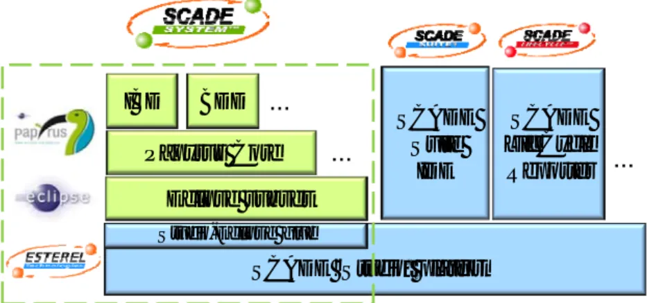
SCADE System architecture
From an architecture point of view, SCADE System is built on the same platform as SCADE Suite and includes Papyrus, an open source component (under EPL license) based on Eclipse. The SCADE Suite platform remains the main “host” platform, but most Eclipse platform User Interface (UI) elements involved in the Eclipse plugins making up Papyrus are transparently intercepted and “reframed” to fit in the SCADE Studio platform at the appropriate place. This fine-grained integration allows system and software teams to share the same environment. Furthermore, and thanks to Eclipse, other model-based tools can be added to the environment. This architecture is pictured Figure 1.
Figure 1 – Technical architecture of SCADE System.
Finally, the concepts of “workspaces”, “projects” and “files” are also unified and synchronized between the two platforms, allowing the system projects and software projects to be managed uniformly with configuration management tools. It is even possible for a single project to have both a “system” nature (supported by Eclipse/Papyrus plugins) and a “Scade” nature (supported by native SCADE Suite plugins). Both sides always have an identical view of the project’s resources.
Figure 2 shows the resulting IDE with SysML Block Definition Diagrams and Internal Block Diagrams in the same framework as SCADE Suite diagrams. The selection of a tab in the tree window (left side) switches between the system and the software objects trees.
IBD BDD
Papyrus Core
SCADE “Studio” platform
…
SCADE Suite IDE SCADE LifeCycle Reporter…
Studio-Eclipse glue Eclipse subset…
Figure 2 – Integrated IDE: SCADE System and SCADE Suite windows
SystemSoftware synchronization
Once the system description is complete and checked, the individual software blocks in the system can be refined in the form of models in SCADE Suite. Automatic and DO-178B Level A-qualified code generation can be applied to the SCADE Suite models. Moreover, the SCADE System description can be used as the basis to develop scripts that will automatically integrate the complete application software.
SCADE System avoids duplication of efforts and inconsistencies between system structural descriptions made of SysML block diagrams, IBD and BDD, and the full software behavioral description designed through both SCADE Suite and SCADE Display models. To that effect, a mapping between SysML block interface and SCADE Suite operator interface has been formally defined and implemented in SCADE System Synchronizer.
INCOSE provides guidelines for establishing system engineering activities. In practice, each organization defines its own workflow depending on internal constraints. The better the Commercial Off-The-Shelf (COTS) tool supports the different workflow steps, the more efficient it is; so the tools must offer individual features that can be freely combined to match individual organization processes. To that end, the synchronization action between the system and the software models shall be explicit – it is under the control of the user. Depending on the project organization, the action could be triggered either by the system team or by the software team.
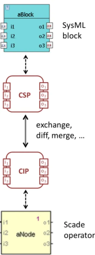
Figure 3 details the complete process:
- The SysML block to synchronize is abstracted automatically with a canonical form, the “Component Specification Proxy”, implemented as a SysML opaque behavior
- The SCADE Suite operator is abstracted automatically with a canonical form, the “Component Implementation Proxy” implemented as a SysML opaque behavior
- As the two abstractions are of same nature, simple diff, merge or exchange between the two proxies realize the synchronization expected.
Figure 3 – SysML-Scade synchronization.
Synchronization with display applications
This synchronization mechanism can be easily extended to other software development environments with the same philosophy. For example, the SCADE Display [6] tool is a versatile graphics design and development environment for critical Human Machine Interfaces (HMI). It is typically used in the aerospace, rail transportation, nuclear and industrial domains for the design of critical embedded display systems such as multi-function displays, head-up displays, digital instrumentation and control panels, etc... From a WYSIWYG design entry automatic code is generated from the SCADE Display KCG™ code generator, and takes credits from its qualification.
The display models managed by SCADE Display receive inputs to control the graphical elements, position, color, etc. Interactive HMI designs are made from primitives for active areas, multiple pointing device or keyboard events management; they provide outputs values to the SW environment interacting with the display. In short, a SCADE Display model has a typed interface exactly as a SCADE Suite operator. When a block in the system model represents a display, the input/output variables dictionary of a SCADE Display model can be synchronized with the system model as presented above for SCADE Suite.
Other system engineering supported activities
In addition to the modeling and the synchronization features presented above, the following advanced features in SCADE System allow a complete industrial process from system engineering to certified embedded code generated with SCADE Suite and SCADE Display.
Fine grain traceability feature, shared with SCADE Suite and SCADE Display; Semantic model diff;
Export of sub-part of a system model;
Automatic generation of documentation, shared with SCADE Suite and SCADE Display.
CSP i1 i2 i3 o1 o2 o3 CIP i1 i2 i3 o1 o2 o3 exchange, diff, merge, … SysML block Scade operator
ARINC 653 use case
This section shows how SCADE System is used for a typical avionics system based on ARINC 653 architecture.
First the Equipments are defined as SysML blocks; a dedicated profile allows architects to provide specific information on the blocks, ports, and connectors representing the inter-equipments connections. SysML Internal Block Diagrams provides the graphical view expected by the architects.
Second, the Equipments are refined with other SysML blocks representing the modules; the same SysML constructions are used.
Third, the Modules themselves are refined into Partitions, again defined with SysML blocks, ports and connectors. At that level, the ports of the Partitions are typed with SW types, some precisely defined, e.g. with enumerated types, some only abstracted, e.g. structured data for which the fields are not defined by the system engineers.
Now the Partitions, as a sub-part of the system model, can be exported as standalone SCADE System models to be implemented by SW specialists, thus avoiding sharing the IP of the whole system model. Another mean, also supported by SCADE System, is the use of model libraries; if a block is defined as a library model together with all datatype it uses, the library itself can be shared with the SW engineers. To initialize the SW design of a partition, the synchronization with SCADE Suite is used; a SCADE operator is automatically generated with all inputs and outputs, named and typed according to the System information. The SW design proceeds with SCADE Suite modeling constructs. In real project neither the system model nor the SW design is done at the first shot; both engineering teams are working in parallel in an increment way. Re-synchronization between the SW interfaces and the system model Partitions can be made either on SW design side, or on system model side. Thanks to the traceability information set automatically between the corresponding elements, the re-synchronization algorithm does not affect the pieces that were synchronized previously, thus does not “break” the usage of these elements in their respective models. The semantic diff feature can be used to establish with the other team the contract of the update requested.
When the SW design and verification is completed, the code can be compiled and loaded on the target. ARINC 653 configuration files and “Glue code” must be written to integrate the code generated by SCADE Suite KCG into the actual Modules of the Equipments. This can be generated from the Modules description in the system model with custom scripts using the model API.
Conclusion and future work
This paper has introduced a comprehensive toolset for model-based System and Software engineering. The system architecture design and the Software design can evolve in parallel, interfaces being re-synchronized automatically on request from either side. The technique has been demonstrated on an ARINC 653 system example.
Model-Based System Engineering scope is not restricted to the modelisation of the system architecture presented in the use case section of this paper. Functional decomposition, analysis and allocation are important aspect that is also be supported by SysML. One analysis mean of high interest for system engineers is the animation/simulation of the functional model. For that, the functions must be described with precise behaviors that can be computer interpreted or compiled. The Scade language brings both a graphical description and a precise, simple, non-ambiguous semantics, making it a good candidate to describe system functions. The AGeSys project, led by Esterel Technologies, has among others, the objective of a deeper integration of SCADE Suite in SCADE System to provide such functional simulation to system engineers.
References
1. “Systems Engineering Handbook, a Guide for System Life Cycle Processes and Activities”, SE Handbook Working Group, INCOSE, January 2010.
2. “OMG Systems Modeling Language (OMG SysML)”, OMG, Version 1.2, June 2010 3. “DO-178B Software Considerations in Airborne Systems and Equipment Certification”,
RTCA/EUROCAE, 1992
4. Papyrus, http://www.eclipse.org/papyrus
5. Listerel Critical Software Lab, http://www.listerel.org
6. Esterel technologies SCADE products, http://www.esterel-technologies.com
7. SCADE Language Reference Manual, http://www.esterel-technologies.com
8. “The Synchronous Dataflow Programming Language LUSTRE”, N. Halbwachs, P. Caspi, P. Raymond, D. Pilaud. Proceeding of the IEEE, September 1991.
9. “A Conservative Extension of Synchronous Dataflow with State Machines”, J.L. Colaço, B. Pagano, M. Pouzet. EMSOFT’05
10. “Bridging UML and Safety-Critical Software Development Environments”, Alain Le Guennec, Bernard Dion. ERTS 2006
11. “SCADE 6: A Model Based Solution For Safety Critical Software Development”, François-Xavier Dormoy. ERTS 2008
12. “Using SCADE System for the Design and Integration of Critical Systems”, Thierry Le Sergent, Alain Le Guennec, François Terrier, Sébastien Gérard, Yann Tanguy. SAE Aerotech Congress 2011

![[PDF] Cours d’informatique Initiation au langage C](data:image/gif;base64,R0lGODlhAQABAIAAAP///wAAACH5BAEAAAAALAAAAAABAAEAAAICRAEAOw==)