The Design of Low-frequency, Low-g Piezoelectric
Micro Energy Harvesters
by Ruize Xu
Bachelor of Engineering, Mechanical and Automation Engineering The Chinese University of Hong Kong (2010)
Submitted to the Department of Mechanical Engineering in partial fulfillment of the requirements for the degree of
Master of Science in Mechanical Engineering at the Massachusetts Institute of Technology
June 2012
ARCHIVES
MASSACHUSETTS INT OF TECHNOLOGYJUN 2
8
2012
LIBRARIES
©Massachusetts Institute of Technology 2012. All rights reserved.
Author
Department of Mechanical Engineering May 11, 2012 Certified by
Accepted by
- - Sang-Gook Kim
Associate Professor f Mechanical Engineering Thpag ,tipervis r
David E. Hardt Chairman, Department Committee on Graduate Theses
The Design of Low-frequency, Low-g Piezoelectric Micro
Energy Harvesters
by
Ruize Xu
Submitted to the Department of Mechanical Engineering on May 11, 2012, in partial fulfillment of the
requirements for the degree of
Master of Science in Mechanical Engineering
Abstract
A low-frequency, low-g piezoelectric MEMS energy harvester has been designed. Theoretically, this new generation energy harvester will generate electric power from ambient vibrations in the frequency range of 200~30OHz at excitation amplitude of 0.5g. Our previous energy harvester successfully resolved the gain-bandwidth dilemma and increased the bandwidth two orders of magnitude. By utilizing a doubly clamed beam resonator, the stretching strain triggered at large deflection stiffens the beam and transforms the dynamics to nonlinear regime, and increases the bandwidth. However, the high resonance frequency (1.3kHz) and the high-g acceleration requirement (4-5g) shown in the testing experiments limited the applications of this technology. To improve the performance of the current energy harvesters by lowering the operating frequency and excitation level, different designs have been generated and investigated. Moreover, a design framework has been formulated to improve the design in a systematic way with higher accuracy. Based on this design framework, parameter optimization has been carried out, and a quantitative design with enhanced performance has been proposed. Preliminary work on fabrication and testing setup has been done to prepare for the future experimental verification of the new design.
Thesis Supervisor: Sang-Gook Kim
Title: Associate Professor of Mechanical Engineering
Acknowledgements
I would like to express my deep gratitude to Professor Sang-Gook Kim, my research supervisor, for his guidance, support, encouragement and useful critiques of this research work. He showed me the true meaning of engineering, reminded me of the big picture when I got lost in a detailed problem, gave me encouragement with tremendous patience when fabrication stuck, and shared with me his great insights on research, career and life. All of these will enormously benefit my future work and life, and I thank him very much.
My grateful thanks also go to Dr. Arman Hajati, my predecessor on this energy-harvesting project. Although we have not met each other, I am familiar with his excellent work, based on which, my research becomes possible. His useful advices and critiques through emails also helped me markedly.
I would like to thank my group mates Stephen Bathurst and Heonju Lee for their generous help. They introduced me the available facilities when I was new to the group, helped me on fabrication processing, especially the PZT deposition, discussed with me on my research and gave insightful advices, and answered any questions I had.
I would like to thank You C. Yoon (Richard), a UROP student in our group from 2011 to 2012 for his great contribution to the setup of testing devices, and Dr. Firas Sammoura, with whom I investigated the multiple coupled beam design.
I would like to extend my thanks to MTL staffs for their help on fabrication processing. I especially want to thank Dennis Ward, Bob Bicchieri, Paul Tierney, Bernard Alamariu, Dave Terry and Vicky Diadiuk. My special thanks go to Ray Hardin for his help and administrative support.
Finally, I wish to thank my parents for their love, sacrifices, support and encouragement.
Table of Contents
C hapter 1 Introduction ... 13
1.1 Thesis Objective and Contribution...14
1.2 Thesis O rganization ... 14
Chapter 2 B ackground ... 16
2.1 Vibration Energy Harvesting...16
2.2 Piezoelectric Energy Harvesting ... 19
2.2.1 Fundamentals of Piezoelectricity... 19
2.2.2 Piezoelectric Energy Harvesters Based on Different Energy Sources ....21
2.2.3 Recent Advances in Vibration Energy Harvesting ... 23
2.2.4 Previous Work of Our Group ... 29
2.2.5 Nonlinear Resonance Based Energy Harvesting ... 33
C hapter 3 D esign ... 38
3.1 Criteria on the Design of Piezoelectric Vibration Energy Harvesters...38
3.2 D esign G oals... 4 1 3.3 D esign Ideas ... 42
3.3.1 Multiple Doubly Clamped Beams ... 42
3.3.2 C ircular Plate ... 44
3.3.3 Large In-plane Proof Mass ... 47
3.3.4 Coupled Beams Design...49
3.3.5 Doubly Clamped Serpentine Beam Design ... 54
3.3.6 Doubly Clamped Spiral Beam Design...55
3.3.7 Parameter Optimization on Straight Doubly Clamped Beam Design ... 66
3.4 Proposed Design: Optimized Doubly Clamped Beam Resonator ... 66
3.4.1 Design Parameters ... 66
3.4.2 Design Framework...77
3.4.3 B eam C om position ... 79
3.4.4 Q uantitative design ... 86
Chapter 4 Fabrication... 92
Chapter 5 Testing ... 99
5.1 Electrom echanical Testing M easurem ent... 99
5.1.1 Testing Setup ... 99
5.1.2 V ibration Testing Results...102
Chapter 6 Sum m ary ... 104
6.1 Thesis Sum m ary ... 104
6.2 Future W ork...105
List of Figures
Figure 2-1 Mechanical lumped model of linear resonator based energy harvester...18 Figure 2-2 Schematic of a common cantilever based piezoelectric energy harvester [9].
... 2 1 Figure 2-3 Schematic of a vibro-impacting power harvester [12]...22
Figure 2-4 A cantilever bimorph in harvesting energy from flowing water [20]. ... 22 Figure 2-5 Photograph of fabrics worn on the elbow joint and the finger [28]...23 Figure 2-6 (a) A schematic diagram of the magnetic levitation system [48]. (b) A
schematic diagram of cantilever - magnets energy harvester [49]. (c) A schematic of bi-stable oscillator based broadband energy harvester [50]...26 Figure 2-7 (a) Schematic diagram of piezoelectric buckled bridge [51]. (b) A schematic
of MEMS electrostatic energy harvester with nonlinear suspension [52]. ... 27 Figure 2-8 1st generation PMPG. (a) SEM image of cantilever beam. (b) Schematic of
interdigitated electrodes. (c) The load voltage and power delivered to the load vs. load resistance at 13.9 kHz resonance respectively. [6] ... 30 Figure 2-9 3'd generation PMPG. (a) Photo of fabricated device on a coin. (b) Dynamic response of nonlinear resonator. (c) Open circuit voltage versus frequency [5]. (d) Estimated power versus frequency [5]... 32 Figure 2-10 Lumped models of nonlinear resonator based energy harvester. (a) Simplified
dynamic model. (b) Mechanical lumped model. (c) Electrical lumped model. (d) Electrical lumped model with impedances. ... 36 Figure 2-11 Comparison between linear and nonlinear systems behavior (simulation). (a)
Deflection of linear and nonlinear systems versus damping ratio. (b) Maximum extractable electrical power comparison... 37 Figure 3-1 Schematic of multiple doubly clamped beam designs...43 Figure 3-2 (a) Width to length ratio versus number of beams. (b) Area versus number of
b eam s. ... 4 4
Figure 3-3 Schematics of circular plate design. (a) Top view. (b) Side view. (c)
D im ensions of circular plate ... 46 Figure 3-4 Schematics of large in-plane proof mass designs. ... 49 Figure 3-5 Models of coupled beam design. (a) Schematic of coupled beam design. (b)
M echanical lum ped m odel... 51
Figure 3-6 Bode plots of one coupled beam design example. (a) X1 before coupling. (b)
X2 before coupling. (c) X1 after coupling. (d) X2 after coupling...53
Figure 3-7 (a) Schematic of serpentine beam design. (b) Numerical simulation of strain distribution of serpentine beam ... 55 Figure 3-8 Strain distribution of curved beams. (a) Single spiral beam. (b) Curved corner.
(c) O-ring beam. (d) S-beam. (e) Doubly clamped spiral beam. ... 57 Figure 3-9 S-beam. (a) Schematic of doubly clamped S-beam. (b) Geometries for the
calculation of load-deflection characteristic. ... 58 Figure 3-10 Comparison of analytical and numerical results of load-deflection
relationship of S-beam ... 64 Figure 3-11 Four spiral beams with different design parameters. ... 65 Figure 3-12 Normalized force-deflection for four different spiral beams. ... 65 Figure 3-13 Bandwidth indicator and operating frequency indicator change with the
thickness of the beam ... 70 Figure 3-14 Bandwidth indicator and operating frequency indicator change with the
w idth of the beam ... 71 Figure 3-15 Bandwidth indicator and operating frequency indicator change with the
length of the beam ... 72 Figure 3-16 Bandwidth indicator and operating frequency indicator change with the
Young's m odulus of the beam . ... 73 Figure 3-17 Bandwidth indicator and operating frequency indicator change with the
residual stress in the beam . ... 74 Figure 3-18 Jump-up and jump-down frequencies change with the residual stress in the
Figure 3-19 Bandwidth indicator and operating frequency indicator change with the proof m a ss...7 6 Figure 3-20 Bandwidth indicator and operating frequency indicator remain constant with
varying width and mass compensation. ... 78
Figure 3-21 Diagram illustrating the design framework...79
Figure 3-22 Schematic of multilayer beam structure...84
Figure 3-23 The beam composition of 3 rd generation device. ... 87
Figure 3-24 The proposed beam composition using silicon nitride as the structural layer. ... 8 8 Figure 3-25 The proposed beam composition using silicon as the structural layer...88
Figure 3-26 Frequency response of the design based on the first beam composition design and 3rd generation m asks... 91
Figure 3-27 Frequency response of the design based on the second beam composition design and 3rd generation m asks. ... 91
Figure 4-1 Fabrication process of 3rd generation design [5]...93
Figure 4-2 Microscopic pictures of pyrolyzed ZrO2. (a) - (d) cracking after pyrolysis. (e) Edge of the wafer with good quality ZrO2 after pyrolysis. (f) Crack-free ZrO2..95
Figure 4-3 Crack-free PZT after annealing... 97
Figure 4-4 Microscopic pictures of interdigitated electrodes. ... 98
Figure 5-1 Overview of electromechanical testing setup. ... 101
Figure 5-2 Open circuit voltage versus frequency of test device...102
Figure 5-3 Output power versus load resistance...103
List of Tables
Table 2-1 Comparison of piezoelectric energy harvesters...28 Table 3-1 Acceleration amplitudes and frequencies of common ambient vibration sources
[2 , 6 1]...4 0 Table 3-2 Parameters of S-beam for comparison of analytical and numerical results.63 Table 3-3 Parameters of four spiral beams ... 65
Table 3-4 Values of design parameters for illustrating the relationships of design param eters and design goals. ... 69 Table 3-5 Summary of relationships between design parameters and design goals....77 Table 3-6 Material properties used for the design optimization...89 Table 3-7 The optimized thicknesses and related characterization for the two proposed
Chapter 1
Introduction
Harvesting energy from ambient environment in macro scale is common in the world. Solar cells, wind turbines, watermills, to name a few, play important roles in power supply. These technologies generate considerable amount of power at large scale, and are believed to be the solution of the environment issues such as pollution and global warming caused by the consumption of fossil fuel. In contrast, energy harvesting at micro scale generates power in microwatts to miliwatts, and it aims to address other problems. The fast development of microelectronics stimulates the growth of portable and wireless devices. But their typical power source - battery has its limitations. Its limited lifespan necessitates periodic replacement, which can be expensive and even impossible. In case of wireless sensor network that is distributed in a large terrain, or monitoring sensors embedded in large civil structures or human bodies, the accessibility is extremely constrained. To extend the lifespan of these devices at low cost, an energy harvester, which perpetually generates energy, is a solution. Recent advances in microelectronics bring the power consumption down to very low level, which narrower the gap between the required power of the electronic devices and the power supply from micro energy harvesters. Micro energy harvesting becomes not only feasible but also desirable.
A number of ambient energy sources exist, such as vibration, waste heat, fluid flow, solar energy etc. Each of them has its unique characteristics and applications. For example, for vibrating embedded system, vibration energy harvesters may be preferred to solar cell since there is no sunlight but kinetic energy. For vibration energy harvesting, there are three main transduction mechanisms: electrostatic, electromagnetic and piezoelectric. Piezoelectric energy harvesting has received much attention due to its ability to directly convert strain energy into electric energy and the ease to be integrated into MEMS-scale systems. Our research focuses on piezoelectric vibration energy harvesting.
1.1 Thesis Objective and Contribution
A design framework of nonlinear resonance based piezoelectric energy harvesters has been devised and presented. The concept of utilizing stretching strain in a beam structure to attain nonlinear resonance and significantly increase the energy harvesting bandwidth was well proved by our previous work up to 2010. To further improve the performance of the energy harvesters to meet the requirements of real applications, a more systematic and deliberate design process is necessary. Therefore, a new design framework has been formulated with considerations of physical constraints and design parameter optimization.
Moreover, a new quantitative design based on our previously developed energy harvester has been proposed. This design was created by following the newly developed design framework, which guaranteed an optimal solution with the available materials and facilities, and physical constraints, within the design space. Simulations have been made to demonstrate the superiorities of the proposed design, including wide bandwidth, low operating frequencies and low-g excitations.
To verify the performance of the improved design, fabrication of the prototype is necessary in future research. Preliminary work on fabrication for the preparation has been done. An electromechanical testing setup has also been built up for future testing.
1.2 Thesis Organization
The thesis presented our recent progress on the piezoelectric energy harvesting research. A thorough review on the discrepancy between real applications and present energy harvesters, design considerations, modeling and theoretical analysis, and related experimental preparations has been made. The first chapter overviews energy harvesting, and introduces the objective and the organization of the thesis. Chapter 2 reviews the
basic theories behind energy harvesting, state of the art of this field and our previous work. Chapter 3 discusses the criteria for the design of piezoelectric vibration energy harvesters, defines the design goals, reviews the design ideas that have been investigated, formulates a design scheme and proposes a quantitative design following that scheme. Preliminary work on fabrication and testing are reported in Chapter 4 and Chapter 5 respectively. A summary of the thesis and future work are concluded in the last chapter.
Chapter 2
Background
Piezoelectric vibration energy harvesting is the intersection of vibration energy harvesting and piezoelectric energy harvesting. A review of both research areas may not only provide a clue on the superiorities of this unique energy harvesting method but also reveals novel ideas that may inspire new designs. A variety of peers' recent work are presented and compared in this comprehensive review to show the state of the art of this research field, the trend of the research development and where we are standing. Along with a brief review of our group's previous work from 2005, a much clearer view can be obtained.
2.1 Vibration Energy Harvesting
Vibration as a common ambient energy source can be found in household appliances (refrigerators, microwave ovens, washing machines etc.), large civil structures (buildings, bridges etc.), industrial plant, automobiles and many others. Kinetic energy in the vibrations can be converted into electrical energy via three main transduction mechanisms: electrostatic, electromagnetic and piezoelectric. The available kinetic energy depends on the frequency spectrum and the excitation level.
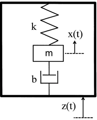
The general model of a vibration energy harvester is a typical mass-spring-damper system as shown in Fig. 2-1. The difference of the transduction mechanisms lies in the damping characteristic. Assume the inertial frame is excited by an external sinusoidal vibration of the form z(t) = Zsin(wot). Then the dynamic equation of the system is,
where m is the proof mass, b is the damping coefficient, k is the spring stiffness and t is the time. The damping coefficient include both the mechanical loss b, and electrical damping be. The steady state solution of Eq. 2.1 can then be found,
x(t) 2 Zsin(ot -- ) Eq. 2.2
(CO2 _ 2)2
+(bcf
where # is the phase angle, expressed as
= tan-,( bo ). Eq. 2.3
k - C02M
The power dissipated in the damper is [1],
m(Z 2 0)_
P=~-2 - -2Eq. 2.4
1- -- + 2{ -)] 2
Expressing Eq. 2.4 in terms of mechanical damping, electrical damping and excitation amplitude,
P= mA 2 Eq. 2.5
4
con(;,
+ m)YSeveral conclusions can be drawn from the observation of Eq. 2.5. The output power is inversely proportional to resonance frequency; therefore the energy harvester should be designed at lowest possible frequency to achieve highest power. The output power is also proportional to the excitation amplitude squared, which limits the energy available for
conversion with low-g vibrations whatever the specific design is. It can also be seen that power is proportional to the proof mass, so a large proof mass is always desirable for energy harvesting. Finally, the term composed of the mechanical and electrical damping ratios implies that the maximum power is achieved when the electrical damping matches the mechanical damping. This is actually a limiting factor for all linear resonator based energy harvesters. Nonlinear resonator based energy harvester does not have this limit and is able to generate more power, which will be analyzed at the end of this chapter.
Figure 2-1 Mechanical lumped model of linear resonator based energy harvester.
Three energy transduction mechanisms are used for vibration energy harvesting: electrostatic, electromagnetic and piezoelectric. Electrostatic generators have the basic structure as a capacitor. Based on different modes, the charge on the capacitor or the voltage across the capacitor remains constant. The energy for transduction comes from the work done against the electrostatic force. It is easy to integrate electrostatic harvesters into microsystems, but input charge is needed for operation.
Electromagnetic generators generate electricity from the relative motion of a magnet to a coil. They do not require a voltage source to operate, but the output voltage is relatively low [2], it drops as the size of the generator decreases [3], and it reduced significantly at micro scale [4]. Moreover, it is still a challenge to implement the assembly of magnets in MEMS scale.
Piezoelectric materials produce charge when subjected to mechanical strain. The piezoelectric generators produce high voltages and low currents, and require no voltage source to operate. Some believe they are more difficult to integrate into microsystems [2], but [5, 6] showed successful implementation of MEMS scale piezoelectric energy harvesters.
2.2
Piezoelectric Energy Harvesting
Piezoelectric energy harvesters can be categorized by their power sources, such as ambient vibrations, impact induced, fluid driven and human powered. Regardless of the power sources, the basic working principle is the same - the environment applies a stress on piezoelectric material so that the mechanical energy in the environment is converted to electrical energy. Before introducing the various harvesting methods, the fundamentals of piezoelectricity are reviewed.
2.2.1 Fundamentals of Piezoelectricity
Piezoelectricity is the outcome of the lack of center of inversion symmetry in atomic structure [7]. Due to this asymmetry, an electric polarization is created in response to a mechanical stress, which changes the charge symmetry and forms electric dipoles in atomic level. The reverse effect, a mechanical strain is induced by an external electric field also exists. The first effect is typically used for sensing, and the latter is used for actuation. A piece of piezoelectric material can be connected to loads and form a loop.
Being subjected to alternating mechanical strains, the varying induced charge will form current and power the load, and this becomes a power generator.
Piezoelectric effect couples mechanical and electrical domains. Mathematically, it connects mechanical stress, which is a second-order tensor, to electrical polarization, which is a first-order tensor, so a third-order tensor is needed. With symmetry, this tensor can be reduced. The mechanical and electrical coupling of linear piezoelectricity can be described by the piezoelectric constitutive equations [8]:
S, =Es 1 ,T +dUE Eq. 2.6
D = dikTkl +ei Ek Eq. 2.7
where S; is the strain component, Tkl is the stress component, Ek is the electric field component, Di is the electric displacement component, SE, d0 and
e7
are the elastic,piezoelectric, and dielectric constants respectively. The subscripts i,
j,
k, 1 run overintegers 1, 2, 3. The superscripts E and T means at constant electric field and at constant stress respectively.
Different piezoelectric materials used in micro-fabrication include quarts, zinc oxide, aluminum nitride, lead zirconate-titanate (PZT), Pb(Mgl/3Nb2/3)03-PbTiO3 (PMN-PT)
and polymer piezoelectrics such as poly-vinylidene fluoride (PVDF). PZT is employed for our energy harvesters in that it has high piezoelectric coefficients and thus will have high output voltage and power. Sol-gel spin coating is used for depositing thin film PZT, which will be explained in more detail in fabrication chapter.
2.2.2
Piezoelectric Energy Harvesters Based on Different
Energy Sources
Vibration Energy Harvesters
Vibration energy harvesters convert kinetic energy of vibrations into electrical energy through piezoelectricity. A typical design is based on a cantilever beam resonator as shown in Figure 2-2. The beam with a proof mass is bonded on a base which is vibrating, so the kinetic energy of the proof mass transfer to the strain energy of the beam in each cycle, and the strained piezoelectric material induces electricity which can power the loads or be stored.
Voltage
Vertical displacement
Figure 2-2 Schematic of a common cantilever based piezoelectric energy harvester [9].
Impact Energy Generators
Impact energy generators ([10-12]) convert mechanical energy which comes from high impact force to electricity through piezoelectric materials. In [10], 30-mm projectiles are launched with a high pressure helium gun to velocities of approximately 300 m/s, and 25 kW output pulse in the order of 1 ts is generated. Another impact generator (11, 12]) consists of a cantilever, which vibrates between two bimorphs (Figure 2-3) and causes deflections on the side bimorphs, so that piezoelectric layers in the bimorphs convert mechanical energy into electricity. The impact based energy generators are in relatively large size, and the applications remain unclear [13].
Figure 2-3 Schematic of a vibro-impacting power harvester [12].
Fluid Driven Generators
Piezoelectric materials can be stressed and generate power in air or water flow as well. Windmill designs [14-16] have been proposed to harvest mechanical energy of wind. In water, wakes formed behind a bluff body induce oscillations in piezoelectric structures, which then become power sources [17, 18]. Energy harvesting from unsteady, turbulent fluid flow using piezoelectric generators has been investigated in [19]. Figure 2-4 shows a cantilever bimorph in harvesting energy from flowing water [20]. [21] demonstrates "microwind" power generation using flow-induced self-excited oscillations of a piezoelectric beam embedded within a cavity. These structures are aimed to convert mechanical energy available in oceans and rivers to electrical energy in milli-watt and even watt power ranges [13].
top and bottom Pressure pp
electrode
Human Powered Generators
Human powered generators include Implantable energy generators and wearable power generators. Effort has been made to implant piezoelectric energy harvester into human bodies to power embedded systems such as sensors and other biomedical devices. One prototype powering orthopedic knee implants is demonstrated in [22]. Energy harvesting from human motion was also studied in [23, 24]. Gonz'alez et al. [25] presents an overview of various sources of mechanical energy available in human body. Shoe inserts also attracted a lot of interests, related research can be found in [26, 27]. [28] proposed a wearable piezoelectric shell structures which harvest energy from human motions at joints and elbow (Figure 2-5).
Arm
Fabric
Figure 2-5 Photograph of fabrics worn on the elbow joint and the finger [28].
2.2.3 Recent Advances in Vibration Energy Harvesting
Increase Efficiency
Material Selection and Parameter Optimization
Piezoelectric ceramic is normally brittle, which limits the strain and the stored strain energy in it. Flexible piezoelectric materials thus have been developed and tested for power harvesting [29-32]. Larger strains provide more mechanical energy available for conversion into electrical energy. Utilizing a more efficient coupling mode such as d33
also leads to higher output voltage and power [6, 33]. Parameters such as electrode size, properties of beams etc. have also been investigated [34, 35].
Circuitry
In addition to improving power harvesting efficiency and energy generation capabilities by redesigning the device, enhancing the power harvesting circuitry is also a means for improvement. More effective circuits [36-38] have been studied. New circuits such as the so-called 'synchronous switch harvesting on inductor' (SSHI) were proved theoretically and experimentally more efficient than conventional circuits [39, 40], and it was proved that SSHI circuit would significantly enhance the performance of nonlinear resonator based energy harvesters as well [5].
Wider Bandwidth Tuning
The natural frequency of the resonator can be tuned by changing the axial tension of a beam through manipulating magnets [41, 42]. Beam dimensions [43], proof mass [44] have also been tuned mechanically to widen the bandwidth. However, frequency tuning inevitably consumes power, the tuning efficiency is low and the tuning range is limited
[45].
Multiple Beams
Shahruz [46, 47] designed an energy harvesting device capable of resonating at various frequencies without adjustment. The device consists of multiple cantilever beams with various lengths and end masses. The combination of the cantilevers, which have different resonant frequencies, created a so-called 'mechanical bandpass filter.' By selecting the length and end mass of each beam, the device had a wide band of resonant frequencies. But this method increases both the size and the cost, a more complex electric circuit may be necessary, and the overall efficiency is reduced.
Nonlinear Resonance
In contrast to a linear resonator, which typically has a narrow bandwidth, nonlinear resonator changes the dynamic response and greatly increases the bandwidth. Nonlinearity may come from magnetic force and special mechanical structures.
Magnetic force has been introduced in linear resonators to provide nonlinear restoring force. The design in [48] had a center magnet placed between two magnets with the poles oriented to repel the center magnet - thus suspending the center magnet with a nonlinear restoring magnetic force (Fig. 2-6 (a)). Another possible design is to fix magnets at the tip of a cantilever (Fig. 2-6 (b)) to achieve Duffing mode resonance [49]. The magnetic forces between the magnets and the iron create a nonlinear spring, whose nonlinearity is determined by the strength of the magnets and the size of the air gap between the magnets and the iron stator. The energy harvesters in [48] and [49] are electromagnetic - the change of magnetic flux in the coils induce electricity. [50] showed a bi-stable Duffing oscillator based piezoelectric energy harvester. The device consists of a ferromagnetic cantilever; two permanent magnets are located symmetrically near the free end (Fig. 2-6 (c)). Due to the attractions, the ferromagnetic beam has three equilibrium positions (statically bi-stable configuration), and the vibration mode has the form of the bi-stable Duffing resonance. The magnetic force based nonlinear resonators typically require macro device size due to the assembly of magnets. The prototypes shown in [48-50] are in macro scale.
Excitation Coi
Iron
V Electrical load (resistor) Piezoceramic X, cosf(t layers Ferromagnetic N N elastic beam Magnets (c)
Figure 2-6 (a) A schematic diagram of the magnetic levitation system [48]. (b) A schematic diagram of cantilever - magnets energy harvester [49]. (c) A schematic of bi-stable oscillator based broadband energy harvester [50].
Nonlinear resonance may also be implemented by designing special mechanical structures. The wideband piezoelectric energy harvester in [51] was realized by exerting an axial compression and forming a buckled configuration, to make a bi-stable oscillator. A piezoelectric beam is clamped on both ends on a base excited vertically. One of the two clamps is free to move to compress and buckle the clamped beam as shown in Fig. 2-7 (a). [52] demonstrated an electrostatic energy harvester utilizing a mechanical softening spring to increase the bandwidth. The nonlinearity was achieved by using the suspension beam with an angle. When the spring deflects in the negative direction of the x-axis, a compressive axial force is first built up, and beyond a certain displacement, the axial force changes to tension. In positive direction along x-axis, axial force is always tensile. The asymmetric force-displacement in the suspension therefore has a nonlinear spring softening behavior.
RL
(a)
(b)
Figure 2-7 (a) Schematic diagram of piezoelectric buckled bridge [51]. (b) A schematic of MEMS electrostatic energy harvester with nonlinear suspension [52].
Lower Frequency
A conversion from low frequency to high frequency has been presented to lower the operating frequency of energy harvesters. Instead of harvesting energy from single resonator, the energy absorption from environment and energy conversion from mechanical domain to electrical domain has been divided to two steps. The ambient vibrations, excite a resonator at low frequencies in the first stage, and then the kinetic energy is transferred to a much higher frequency resonator for conversion at the second stage [53]. This method may enable power harvesting at low frequency. [54]
m/s2), and low frequency (2-30 Hz) with an average power of 2.3 pW. The device absorbs ambient kinetic energy by using a large mass. The low-frequency motions of the suspended mass magnetically excite the magnets in coils, which then resonate at higher frequencies. [55] showed a piezoelectric version of energy harvester using the same up-converting method. To resonate with low-frequency ambient vibrations, the resonators in
[54] used a large mass, which makes the whole device size increases; the volume of space where components can move is 43 cm3 (68 cm3 including the casing case).
Some piezoelectric energy harvesters are compared in Table 2-1.
Table 2-1 Comparison of piezoelectric energy harvesters.
Reference Dimension Power Energy/power Voltage Frequency Load density
White 2001 [56] N/A 2ptW N/A 0.816V 80 Hz 333kK2
Shenck 2001 [26] 5 x 5 x 0.038cm PZT 8.4mW 8.8mW/ cm3 64.8 V N/A 500kn Roundy 2003 [2] 1 cm3 ~80ptW -80[tW/ cm3 ~6V 100Hz 250k Jeon 2005 [6] 170 pm x 260 pm 1IpW 0.74mW h/cm2 2.4 V 13.9kHz 5.2MK2 (PZT) Muralt 2009 [57] 0.8mm x 0.4mm x 1 .4W 437 pW/cm2 1.6 V 870Hz -2pm (piezo) Liu 2011 [58] - 85.5nW 33pW/cm3 164 30-47Hz 1 M9 mV Massaro 2011 Length ~ 500pm 1.3nW 30.2mW/ cm3 2.5 mV 64Hz 11 K2 [59] Thickness ~ 0.7pm Miller 2011 [60] - 1.7nW - - 31-232Hz 9 k9
2.2.4 Previous Work of Our Group
1't Generation Design
In 2005, a PZT based MEMS power-generating device was developed in our group [6]. The basic structure was a cantilever with a proof mass at the end (Figure 2-8 (b)). The top electrode was patterned into an interdigitated shape to employ the d3 3 mode of the piezoelectric transducer (Figure 2-8 (a), (b)). This new configuration made the device generate 20 times higher voltage than that of the d3n mode design. At the resonant
frequency 13.9 kHz, generated ipW of continuous electrical power at 2.4Vdc. The corresponding energy density is 0.74mWh/cm2, which compares to the values of lithium ion batteries. (a) Interdigitated Electrode + - + - + -+ - + Proof Mass ZrO2 membrane (b)
5.01 1 1.2
4.5 -m- Power delivered to Load
4.0 U1.0 0.8 3 3.0 -1 2.5 0.6 0a M 2.0 0) 00. 1.5 -, 0.4 1.0 02
0.5 5f --rc-- Voltage across Load
0.01 0.0
0 2 4 6 8 10
Load Resistance [Mu]
(c)
Figure 2-8 1"t generation PMPG. (a) SEM image of cantilever beam. (b) Schematic of interdigitated electrodes. (c) The load voltage and power delivered to the load vs. load resistance at 13.9 kHz resonance respectively. [6]
3rd Generation Design
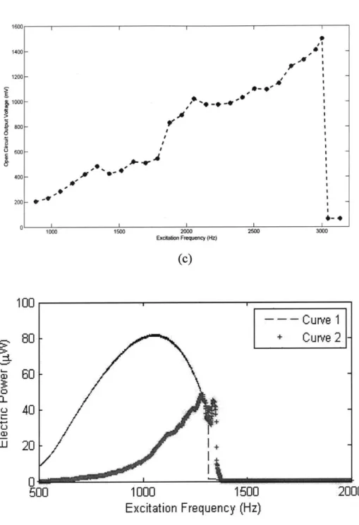
In 2010, Arman Hajati successfully developed a novel piezoelectric micro energy harvester, which achieved an ultra-wide bandwidth of >20%, a maximum peak-to-peak voltage of 1 .5V (Figure 2-9 (c)), a maximum extractable power of 45pW (Figure 2-9 (d)),
and high power density of 2W/cm3. More than one order of magnitude improvements in
comparison to the devices previously reported in both bandwidth and power density convinced us that this is a promising way to harvest minute energy and to be employed for real-world applications.
The basic design is based on a doubly clamped beam resonator. Four of these resonators are arranged perpendicular to each other and form one energy harvester, which is about a US quarter coin size 6mmx6mmx5.5gm (LxWxH) (Figure 2-9 (a)). At large deflection, a net stretching besides bending is activated, resulting in non-linear resonance, which completely changes the dynamic response (Figure 2-9 (b)) and turned out to be desirable for energy harvesting, this will be explained in detail in the next chapter. Although the
new design manifests superiorities, the test results showed a resonance frequency of 1.3kHz and excitation amplitude was at 4-5g. This is a discrepancy from the real ambient environment, which usually have vibrations of -100Hz and <0.5g. Therefore, new designs for closing the gaps are needed.
(a) -0 E 0: 0 -* 45 40 35 30 25 20 15 10 5 0 100 200 300 400 500 600 700 800 900 1000 1100 1200 Excitation Frequency (Hz) (b) Unstable Root Unique Root
High-Energy Stable Root Low-Energy Stable Root
,Wul 'II 0-I X' Ex (c)bon Freqecy (1z) (c) 1000 1500 Excitation Frequency (Hz) (d)
Figure 2-9 3d generation PMPG. (a) Photo of fabricated device on a coin. (b) Dynamic response of nonlinear resonator. (c) Open circuit voltage versus frequency [5]. (d) Estimated power versus frequency [5].
1400 1200[I I 1000- 800- 600- 400-200k1W -' 1000 1500 2500 100 3000 80 60 40 20 a. 0 C-) U, 0 0 500 2000 1)
2.2.5 Nonlinear Resonance Based Energy Harvesting
Statics
For designing a transversely vibrated beam resonator, statics is the starting point. At large deflection, which means the deflection is comparable the thickness of the beam, a doubly clamped beam not only bends but also be stretched and elongate so that the fixed boundary conditions are satisfied and the whole structure remain geometric compatibility. By using variational method, the load-deflection characteristic for a doubly clamped rectangular beam with a point load at center is,
F = -- 4+ + 8(1_ Eq. 2.8
(6 _V 2. L 8 E
The solution has two parts; the first part is a proportion to deflection and results from the small-amplitude bending, while the second nonlinear term comes from stretching and is proportional to deflection cubed. The nonlinear term implies that the equivalent stiffness of the beam is not constant but increases as the deflection get larger. A scrutiny on this equation provides insights on understanding the nonlinear spring and the design of it.
Dynamics
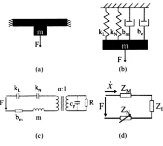
To model and analyze the doubly clamped beam-based nonlinear resonator, it is assumed that the base is fixed and a sinusoidal force is applied to the proof mass. Then a mechanical lumped model (Figure 2-10 (b)) and electrical lumped models (Figure 2-10 (c), (d)) are constructed, which consist of a proof mass, a linear spring due to bending, a nonlinear spring due to stretching, a mechanical damper and an electrical damper. The dynamic equation of the mass-spring-damper system is,
mi+bik+kLx+kN 3= F cos (ot) Eq. 2.9
where m is the proof mass, b is the total damping including structural damping, aerodynamic damping and electrical damping, kL is the linear stiffness, kN is the nonlinear stiffness, co is the excitation frequency, and t is time.
Substituting linear and nonlinear stiffness's and damping coefficients into Eq. 3.2 and solving for the deflection, a cubic equation can be obtained [5]:
1+lb x> + FkN a ss2 ]4 Eq. 2.10
+((b+b,+bs)2W2+(kL 0)2]X2 2 2 = 0
where bs, ba, be are structural damping, aerodynamic damping and electrical damping respectively, and a is the excitation acceleration. The multiple solutions of Eq. (3.3) are illustrated in Figure 2-9 (b). The tilted peak resulting from the nonlinearity of Duffing mode resonance indicates a wider bandwidth, if the resonator can stay on the upper envelope (high-energy) of this curve. Depending on the initial conditions, a system may work at different regions denoting by different colors in Figure 2-9 (b). If sweeping frequency from low to high, the system will work in the unique solution region first at small deflection, then the deflection will increase along the high-energy stable region, until it jumps down to low energy stable region. If sweeping the frequency high to low, the response will go along the low-energy stable region until it jumps up to high-energy
stable region again. The jump-down and jump-up frequencies are marked by blue and green arrows respectively in Figure 2-9 (b). It is obvious that working in high-energy stable region is desired, so the system should be designed to make the frequencies of ambient vibrations fall in this range.
The deflection of linear resonators drops dramatically when the system goes off-resonance, and a sharp peak that has a narrow bandwidth is formed. In contrast, it can be seen in Figure 2-9 (b) that for a nonlinear resonator, the deflection increases steadily in a wide frequency range before it jumps down to low level. By equating the stored energy
due to nonlinear stiffness and an equivalent linear stiffness, we can find the equivalent stiffness to be -kNx2. Then, the equivalent natural frequency of the undamped nonlinear
4
resonator can be estimated as [5],
_k +0.75kN 2
Eq. 2.11
When the excitation frequency is lower than the jump-down frequency, the deflection tends to decrease from the peak value, but that decrease also lowers the resonant frequency of the nonlinear system, so that the system keeps working close to resonance. The nonlinear stiffness acts as a negative feedback which results in a much wider frequency range compared to a linear system.
Wide Bandwidth
In linear systems, the electrical impedance should match the mechanical impedance to achieve maximum power [61]. But for a nonlinear system, electrical damping can surpass the mechanical impedance to generate higher output power. By combining the mechanical elements in Figure 2-10(c) except for nonlinear spring, a simplified electrical circuit with impedances is generated in Figure 2-10 (d). ZM, ZN, ZE are mechanical impedance, impedance of nonlinear spring and electrical impedance respectively. It is obvious that when electrical impedance increases, the total impedance tends to increase, which will make the deflection drop, but the variable nonlinear impedance 0.75kN 2 also
S
tends to decrease because of the smaller x, and that tends to decrease the total impedance and increase the deflection. Consequently, this nonlinear impedance serves as a negative feedback and stabilizes the deflection when electrical damping changes. This effect can be clearly seen in Figure 2-11 (a) which compares the normalized deflections of a linear system and a nonlinear system with various total damping. Figure 2-11 (b) shows that for either fixed or varying electrical damping, the bandwidth of nonlinear system is much wider than that of linear systems.
Since extractable electrical power is proportional to electrical damping, we can increase the output power by increasing electrical damping until it pushes the resonator into instability, resulting in jump-down to low energy state. A smart electronic interface such as adaptive SSHI will be ideal to implement this. Figure 2-11 (b) compares the maximum extractable power of linear and nonlinear systems.
k b F F (a) (b) kL kN W z N F-P R F1 Z z (c) (d)
Figure 2-10 Lumped models of nonlinear resonator based energy harvester. (a) Simplified dynamic model. (b) Mechanical lumped model. (c) Electrical lumped model. (d) Electrical lumped model with impedances.
Deflection at 115 Hz with different damping ratios -Nonlinear 0.8 -inear 0~ 0.6-(a)% S0.4- 0.2-0 00 105 0.1 0.15 0.2 0.25 Damping Ratio -Linear: b, = bm Fi e 21 CNonlinear: b, = bm DNonlinear: max b e 20 10, E 0 100 200 300 400 500 600 2 Excitation Frequency (Hz)
Figure 2-11 Comparison between linear and nonlinear systems behavior (simulation). (a)
Deflection of linear and nonlinear systems versus damping ratio. (b) Maximum extractable electrical power comparison.
Chapter 3
Design
3.1 Criteria on the Design of Piezoelectric
Vibration Energy Harvesters
From a comprehensive review on the history of energy harvester development and the state-of-the-art progress made in this area, the author would like to make a discussion on the criteria of a good piezoelectric vibration energy harvester design and the design guidelines.
The criterion of a good design for ambient vibration energy harvester may be summarized as follows:
e Compactness e Output Voltage
e Output Power (Density) e Bandwidth
" Operating frequency * Vibration Level
e Lifetime
A compact design guarantees good compatibility when embedding into larger systems. A great portion of vibrational energy harvesters are aimed at powering wireless sensor networks, embedded systems in automobile and civil structures, and implantable devices in human body. In these applications, a compact size is almost necessary to make energy harvester a feasible power source. Moreover, MEMS scale energy harvester is able to make full advantage of micro-fabricaion, which makes it possible to manufacture
low-cost energy harvesters in large scale. Miniaturized designs also tend to increase the energy density of the device.
Like all power sources, voltage is one of the most important parameters characterizing the performance. The voltage should be high enough to power the target devices, which may vary according to the applications. Theoretical analysis shows that piezoelectric energy harvesters are able to provide high voltages. From the review, the demonstrated devices which provide from millivolts to several volts also proved this experimentally. Using d3 3 modes, high voltage is not a challenge any more, and it enables the piezoelectric energy harvesters to power a great variety of devices.
Output power or power density is another key parameter in that it directly relates to what kind of load devices can be powered. Power density is more important than output power when comparing different devices, since the size of piezoelectric energy harvesters varies much, and output power is proportional to the volume of the piezoelectric materials. Thus, power density provides a more accurate measure on the efficiency of the whole device. A smaller device with a high power density may be easily stacked to provide high power needed at a high total efficiency.
Bandwidth was not fully recognized as a key parameter at the beginning of the development of piezoelectric energy harvesters, but it has attracted enough attention from researchers in the past several years. The importance of bandwidth arises from the inherent nature of ambient vibrations, which is that the frequency of the vibration varies with time. The conventional linear resonance based energy harvesters suffers from the gain-bandwidth dilemma, which means for a high gain design, which is desirable for efficient energy conversion, the bandwidth is inevitably narrow. For example, the design in [7] has a 2% bandwidth. Such a narrow bandwidth implies a significant decrease in generated power in real applications, as the frequency varies. Hence, knowing the frequency spectrum of the vibration in target applications is important, and the energy
harvester should have a wide enough bandwidth to generate power in that specific spectrum.
Roundy et al. [2] and duToit et al. [61] have examined the vibrations from some common ambient vibration sources, their acceleration amplitudes and excitation frequencies are listed in Table 3-1. It can be concluded that typical ambient vibrations have accelerations below 1 g and excitation frequencies below 200 Hz.
Table 3-1 [2, 61].
Acceleration amplitudes and frequencies of common ambient vibration sources
Vibration Sources Car engine compartment Base of 3-axis machine tool Blender casting
Microwave oven side Clothes dryer
Car instrument panel
Door frame just after door closes HVAC vents in office building Windows next to a busy road Car hood-3000 rpm
Second story floor of busy office A/C duct side (high setting) Office desk
Computer side panel Bridge railing Small tree Accl. [m/s2] 12 10 6.4 4.2 3.5 3 3 0.2-1.5 0.7 0.26 0.2 0.1 0.09 0.04 0.02 0.003 Freg. [Hz] 200 70 121 148 121 13 125 60 100 148 100 54 120 276 171 30
To resonate the energy harvester and generate maximum amount of power, the natural frequency should match that of the ambient vibrations. Many energy harvesters, especially those in MEMS scale have a resonant frequency in the order of kHz or even higher, which may render them useless in real applications. A challenge is to lower the resonant frequency of the MEMS scale energy harvester to 102 Hz range.
Similarly, the excitation level of ambient vibrations is typically small compared to the usual setting of experiment testing. To demonstrate a practical design, energy harvesters
should be tested with low-g vibrations. Since the available energy is proportional to g-level, design considerations should be made to compensate this weaker excitation to generate a considerable amount of power.
Lastly, the lifetime of the piezoelectric energy harvester should be taken into account. The original purpose to adopt generative power sources such as piezoelectric energy harvesters and replace non-generative power supplies such as batteries is that the lifetime of batteries is limited, while theoretically energy harvesters generates power perpetually as long as there is a ambient energy source such as vibrations, thermal gradient, fluid flow and so on. However, the real device may suffer from material fatigue, cruel environment and other unexpected conditions. To make sure energy harvesters have a much longer lifetime than non-generative power sources is necessary. Not much research has been done to investigate the lifetime of piezoelectric energy harvesters, in the future, research on material, packaging and some other aspects may carry out when commercializing these devices.
3.2 Design Goals
As reviewed in background chapter, our group has developed an ultra wide-bandwidth micro-energy harvester by exploiting the non-linear resonance of a doubly clamped MEMS-scale resonator. Two orders of magnitude improvements in both the bandwidth (>50% of the peak frequency) and the power density (up to 2W/cm3) in comparison to the devices ever reported, a maximum peak-to-peak voltage of 1.5V, plus a compact size as a US quarter manifest the superiorities of the new design. However, the high resonant frequency (1.3kHz) and the high-g acceleration requirement (4.5g) prevent this technology from being applicable to real applications. Therefore, the design goals for a new generation of design are clearly defined: to lower the working frequency to under 200 Hz and the excitation force level to below 0.5g while keeping the good features of the previous design. Toward this goal, theoretical modeling and analysis, numerical
simulations, explorations of different design ideas and parameter optimization have been done to generate a new improved design. The following sections in this chapter present these work in detail.
3.3 Design Ideas
At the beginning stage of design, different new design ideas were generated. Each one of them was brought about for some considerations. Investigations on them in different depth were made. To avoid research on the similar ideas in the future and to keep a record of the design ideas and related thoughts on them for later design use, it might be beneficial to briefly explain these ideas before diving into details on the proposed designs.
3.3.1 Multiple Doubly Clamped Beams
The idea of employing multiple beams rather than a single doubly clamped beam is to increase the stability of the resonant structure. As shown in Figure 3-1, with more beams, the clamped ends are in more directions, the vibration in these directions are prohibited, and only out of plane motion dominates. Moreover, it has been proved that multiple clamped beams resonator is equivalent to a single clamped beam, and shows a nonlinear response.
The change of geometry from a single beam to multiple beams changes the width to length ratio, which is related to resonant frequency, and the effective area, which is related to output power. The relationship between the number of beams and w/l ratio and effective area has been investigated. Assume the length of the outer rectangle remains the same, which limit the device size, and the apothem of the inner polygon remains the same, which fixed the size of the proof mass, then we have the formula of w/l ratio for different number of beams:
rtan
-w =N. 2N1
R
and the formula of the effective area is,
A =4Nr(R -r)-tan 2N
2N1
Eq. 3.1
Eq. 3.2
Figure 3-1 Schematic of multiple doubly clamped beam designs.
To see how w/1 ratio and effective area change with number of beams, we may choose R to be 2.5mm and r to be 0.5mm, then Figure 3-2 (a) shows the trends. As can be seen, w/l ratio decreases with number of beams but is bounded to -0.31, which limited the lowering the frequency. Effective area also decreases with increasing number of beams (Figure 3-2 (b)), which means lower power since the output power is proportional to the effective area. Hence, this design has been abandoned.
wA Ratio vs. No. of Beams
0 10 20 30 40 50 60 70 80 90 100
Number of Beams
(a)
Area vs. No. of Beams
7.8 7.6 7.4 7.2 27 6.8 6.6 6.4 0 10 20 30 40 50 60 Number of Beams (b) Figure 3-2 (a) Width to length ratio versus number beams.
70 80 90 100
of beams. (b) Area versus number of
3.3.2 Circular Plate
When searching for mechanically stable designs, a circular plate emerges. Circular plate is a natural extension of multiple doubly clamped beam designs discussed above, we may imagine a circular plate is composed of an infinite number of doubly clamped beams.
0 0.4 0.39 0.38 0.37 0.36 0.35 0.34 0.33 0.32 0.31
When clamped the edge of a circular plate and loading at the center, there will only be out of plane deflection and no hoop deflection or rotation as may happened in a single doubly clamped beam, which would take part of the strain energy away. Therefore, a circular plate is a stable structure, and a possible design was made as shown by the schematic in Figure 3-3. A circular plate is clamped at the edge and a cylindrical proof mass is at the center of the circular plate. PZT would cover the full top surface and a curved d33 electrode was specially designed for the circular geometry.
PZT
Proof Mass
Electrodes
(a)
Electrodes Membrane Structure
I
I
(b)
45
Ha
-1h
Load P
(c) Figure 3-3 Schematics of circular plate design. Dimensions of circular plate.
(a) Top view. (b) Side view. (c)
Although circular plate has unparalleled stability, one important concern is that if the circular plate structure still possess nonlinearity as a single doubly clamped beam does. According to [62], at small deflection, the vertical deflection on a clamped circular plate with a center point load can be found by:
Pr2 r P
w = log -+
(a2
-r2)81cD a 167cD Eq. 3.3
where P is the center point load, w is the vertical deflection at r, a is the radius of the circular plate, D is the flexural rigidity of the plate and is:
D= lEh2
12 (1- v2)
Eq. 3.4
where h is the thickness of the plate, E is the Young's modulus, v is the Poisson's ratio. If Poisson's ratio is 0.3, the center load and the center vertical deflection can be calculated
as,
Eh3 P~ 4.60- a2 W
which shows a linear relationship. However, we should expect something different would happen just as a straight doubly clamped beam. At large deflection, the center vertical deflection and center point load has the relationship [62]:
+ A - = B Pa2
Eq. 3.6
h h Eh4
where wo is the vertical deflection of the center, h is the thickness of the plate, a is the radius of the circular plate, E is the Young's modulus, A and B are coefficients. For immovable edge circular plate, A is 0.443 and B is 0.217 [62]. Plug in these constants and rearrange Eq. 3.6 yields this load-deflection characteristic:
Eh3 AEh
3 Eh3 + Eh 3
P = 2 Wo0 + -7WO 2 ~ 4.61 2 wo +2.04-2wo0 Eq. 3.7
aBaW+a a a
Eq. 3.7 is similar to the load-deflection of a doubly clamped beam. The solution has two parts, the first part is linear and the second has the deflection cubed. It is obvious that at large deflection, a circular plate behaves like a stiffening spring which is similar to a clamped beam. However, circular plates have larger stiffness, which makes it harder to bring the resonant frequency down.
3.3.3 Large In-plane Proof Mass
To lower the resonant frequency while keeping mechanical stability, large in-plane proof mass with new beam arrangements were designed. Figure 3-4 (a) shows a crossing beam with four ends fixed and a large proof mass sits in the center. The structure is equivalent to a doubly clamped beam and with enhanced stability by restraining two perpendicular directions. Figure 3-4 (b) shows another scheme, which consists four doubly clamped beams and one big proof mass in the center. Although these designs have their merits, they have smaller effective areas, and for the second design, the vibrating proof mass will twist the beams because of the asymmetry.
Doubly-clamped beam 7- Proof mass (a) I
Doubly clamped Proof mass beam
Doubly clamped beam Proof mass
(c)
Figure 3-4 Schematics of large in-plane proof mass designs.
3.3.4 Coupled Beams Design
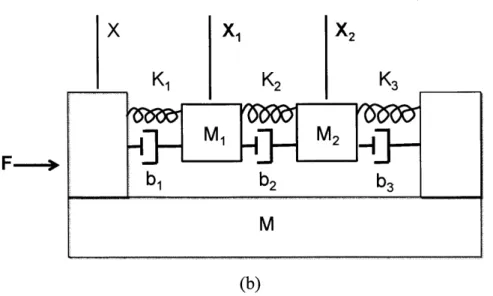
Prof. Firas Sammoura and I have investigated coupled beams design, since it is based on a different working principle might have a wide bandwidth. The basic idea is to make a multiple mass-spring-damper systems with different resonance frequency (different stiffness and masses which can be designed), and couple them (Figure 3-5 (a)) so that when excitation frequency is close to the natural frequency of one of the system, it increase the vibration of other non-resonating systems, and this interference can make the whole system have a wider bandwidth.
Mechanical modeling with two mass-spring-damper systems with one coupling has been made (Figure 3-5 (b)). The transfer functions are,
Xi BMI + CM2 Eq. 3.8 F (AB-C2)M 2-CM + AM2 Eq. 3.9 F - (ABC2)M where A, B, C are A=M Is2 +(b, + b 2)s+(K, +K2) Eq. 3.10 B = M2s 2 +(b 2 +b3)s+(K2 +1K3) Eq. 3.11 C=b2s+K 2
K
1Beam1
M
1Proof Mass
1
Proof Mass 2
Coupling
x1 K1
X2
K2
(b)
Figure 3-5 Models of coupled beam design. (a) Schematic of coupled beam design. (b) Mechanical lumped model.
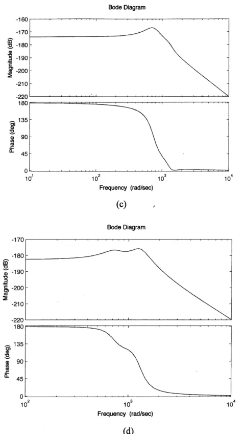
Choosing all the parameters so that the two mass-spring-damper systems have slightly different natural frequencies, and plugging in those numbers, we can obtain the Bode plots for X1 and X2 before and after coupling (Figure 3-6). The results show that the
bandwidth is widened, but at the same time, the magnitudes drop, which means less power can be generated. This trade-off made us give up this design.
51
x
Bode Diagram -10 -170 -180--190 c -200 -210 -220 180 135- 90- .-45 -5 0 10 102 103 10 Frequency (rad/sec) (a) Bode Diagram -10 -170 -180-3 -190 a -200 -210 -220 180 135-o -90 C,) 45- -0 -102 103 104 Frequency (rad/sec) (b) 52
![Figure 2-5 Photograph of fabrics worn on the elbow joint and the finger [28].](https://thumb-eu.123doks.com/thumbv2/123doknet/14687640.560517/23.918.181.715.465.663/figure-photograph-fabrics-worn-elbow-joint-finger.webp)