Design and Implementation
of an Intelligent Ideation Database
by
Kai Wei Hong
rCT
2
9
1997
Submitted to the Department of Electrical Engineering and Computer Science in Partial Fulfillment of the Requirements for the Degrees of
Bachelor of Science in Computer Science and Engineering
and Master of Engineering in Electrical Engineering and Computer Science at the Massachusetts Institute of Technology
May 27, 1997
Copyright 1997 Kai Wei Hong. All rights reserved.
The author hereby grants to M.I.T. permission to reproduce and to distribute publicly paper and electronic copies of this thesis
and to grant others the right to do so.
I _
I - 1
(I
Departmento lectrica"Engineering and Computer Science May 27, 1997
J .
A f
Certified by I! - 1! , M
' I Nam P. Suh
Ralph E & Eloise F Cross Professor and hanical En gineerg Department
J•. /--fis sp isor
Arthur C. Smith Chairman, Department Committee on Graduate Theses Accepted by
Authnr L JI
Design and Implementation of an Intelligent Ideation Database
by Kai Wei Hong
Submitted to the
Department of Electrical Engineering and Computer Science May 27, 1997
In Partial Fulfillment of the Requirements of the Degrees of Bachelor of Science in Computer Science and Engineering
and Master of Engineering in Electrical Engineering and Computer Science
ABSTRACT
By applying the axiomatic design method, a knowledge representation is created to
support the storage, retrieval, and query of design objects. The Ideation Database is built around the representation. Its purpose is to generate possible design solutions, analyze those proposed solutions, and inform the designer of the results. The application architecture and user interface are presented, along with a case study to demonstrate the use of the knowledge representation.
The Intelligent Ideation Database enables designers using the AD method to utilize the knowledge of others in the design process. The goal is to prevent redundant design work and aid in the creative process by allowing designers to augment their own body of knowledge with the knowledge of others. As the database is updated with more designs, it becomes an even more effective tool in expanding the human design intellect.
Thesis Supervisor: Nam P. Suh
Acknowledgments
The author acknowledges Professor Nam P. Suh for his patience and guidance throughout the thesis project. His advice and example were invaluable to the author throughout the year.
The author acknowledges the Silicon Valley Group, Inc. for funding this thesis work as part of their own-going support for research in the field of design.
The author acknowledges Peter Filosi, Michael Creighton, David Morris, and Ernest Frazer of SVG Lithography Systems, Inc. for providing the information and assistance needed to construct a case study with which to test the system.
The author acknowledges Vigain Harutunian and Derrick Tate. Their contributions helped the author gain a better perspective on axiomatic design and the design process as a whole.
The author acknowledges Shaun Abrahamson. His feedback helped to formalize a great jumble of ideas. Also, by breaking his collarbone in a freak snowboarding accident, he convinced the author to spend less time snowboarding and more time working on his thesis.
The author acknowledges his family for their support through five years of schooling which culminates with the completion of this master's thesis. Their love and encouragement convinced the author he could accomplish anything he put his mind to.
Dedication
To my father and sister and to my mother in heaven
"[Love] always protects, always trusts, always hopes, always perseveres..."
Table of Contents
The Design and Development of an Intelligent Ideation Database ... 3
A bstract ... 3 Acknowledgments ... ... 5 D edication ... 7 Table of Contents ... 9 List of Figures ... 13 List of Tables ... 15 1. Introduction ... 17 1.1 Motivation ... 18 1.2 Thesis Scope ... 20 1.3 Thesis Overview ... 21
2. Review of Research in Computer Aided Design Tools ... 23
2.1 CANDLE Product Modeling Language ... 23
2.2 Modeling Information in Design Background ... 24
2.3 An Intelligent Object Oriented Approach to Design and Assembly .... 25
2.4 Knowledge Acquisition Method for Conceptual Design ... 26
2.5 Remarks ... 27
3. Overview of Axiomatic Design ... 29
3.1 Domains ... 30 3.2 Functional Requirements ... 31 3.3 Design Parameters ... 32 3.4 Hierarchical Decomposition ... 33 3.5 Zigzagging ... 34 3.6 Design M atrix ... 35 3.7 Independence Axiom ... 37 3.8 Information Axiom ... 38 3.9 Remarks ... 40
4. Thinking Design Machine ... 41
4.1 TDM Concept ... 41
4.2 Architecture of the TDM ... 43
4.4 Remarks ... 45
5. Ideation Database Knowledge Representation ... 46
5.1 Object Relationships ... 47
5.2 Object Data Structure ... 48
5.3 Interaction Model between FRs and DPs ... 50
5.4Remarks ... 53
6. Ideation Database System Architecture ... 54
6.1 Top Level FRs and DPs ... ... 54
6.2 Decomposition of FR1 "Store and retrieve information" ... 56
6.3 Decomposition of FR2 "Interact with the designer" ... 57
6.4 System Hierarchy ... 59
6.5 Remarks ... 59
7. Ideation Database User Interface ... 61
7.1 Analysis View ... ... 62
7.2 Database View ... 64
7.3 Remarks ... 69
8. Implementation ... 70
8.1 Link to a Database System ... 70
8.2 Managing Relationships in Access ... 71
8.3 Generating Combinations of DPs ... 72
8.4 Development Environment ... 75
9. Case Study : Lamp Life Improvement Project ... 76
9.1 Lithography Process ... 76
9.2 Lamp Life Improvement Project ... 77
9.3 Development of the Top Level FR and DP ... 79
9.4 Development of Second Level FRs and DPs ... 81
9.5 Using the Ideation Database ... 82
9.6Remarks ... 83
10. Conclusions... 84
10.1 Knowledge Representation ... 84
10.2 Ideation Database System ... 85
10.3 Future W ork ... 85
References ... 88
Appendix - Code ... 91
Al. ClassList ... 91
A2. CAnalysisView- AnalysisView.cpp ... 92
A3. CDPDialog - DPDialog.cpp ... 99
A4. CFRSelectDialog -FRSelectDialog.cpp ... 105
A5. CIDatabaseDoc -IDatabaseDoc.cpp ... 105
A6. CIDatabaseView -IDatabaseView.cpp ... 106
Design domains ... . 30
Hierarchical decomposition and mapping ... 33
Decomposition by zigzagging ... 35
Examples of the three types of design matrices ... 37
Probability distribution functions for FRs and DPs ... 39
Schematic diagram of the TDM ... 42
Relationships between FR and DP objects ... 47
Interaction model between FR and DP objects ... 52
System hierarchy for the Ideation Database ... 59
Ideation database application structure ... 61
Analysis View form ... 62
FR selection dialog ... 63
Database View form ... 65
Design parameter view dialog ... 66
Attribute dialog ... ... 67
Search dialog ... 68
Implicit relationships in Microsoft Access ... 71
Cathode tip erosion ... ... ... 78
List of Figures
Figure 3-1. Figure 3-2. Figure 3-3. Figure 3-4. Figure 3-5. Figure 4-1. Figure 5-1. Figure 5-2. Figure 6-1. Figure 7-1. Figure 7-2. Figure 7-3. Figure 7-4. Figure 7-5. Figure 7-6. Figure 7-7. Figure 8-1. Figure 9-1.List of Tables
Table 3-1. Analogy among different design problems ... 31
Table 5-1. Data fields for FR and DP objects ... 48
Table 5-2. Examples of state field values ... 49
Table 8-1. Example of the recursive algorithm ... 74
Table 9-1. Top level FR for lamp project ... 80
Table 9-2. Top level DP for lamp project ... 80
Table 9-3. Second level FRs for lamp project ... 81
Chapter 1. Introduction
Design has long been considered more in the realm of art than science. Solutions are often obtained through the application of equal measures of creativity and trial-and-error prototyping. Once obtained and realized in either physical form or simulation form, they are judged subjectively by how they work and whether they satisfy some measurable criteria such as energy efficiency or speed. The good designs also tend to have an aesthetic quality to them that is hard to quantify. However, without an objective approach to guide us, it is difficult to determine and teach good design practice. Experience becomes the only tool that designers can call upon to help them in their attempts to solve new problems. It is also the only way to discern the good designs from the bad ones. It was in this type of environment that axiomatic design was born.
Axiomatic design is a method developed by Professor Nam P. Suh at the Massachusetts Institute of Technology. The AD method provides a set of principles that can assist the design engineer in identifying the good designs from an infinite number of possibilities. There are two main design axioms : the Independence Axiom and the
Information Axiom. These axioms are conceptually simple but enable the designer to
answer several fundamental questions such as : "Is this a good design?" and "Why is this design better than others?" [12]. Chapter 3 of this thesis explores the axiomatic design method more fully.
Once axiomatic design provides the appropriate framework for design documentation and development, software systems can be developed to assist the designer in the process. The goal of this thesis is to design and develop an Intelligent Ideation Database system which utilizes the axiomatic design method to represent, synthesize, and evaluate design data more efficiently and more thoroughly than is possible manually. This research explores part of the concept outlined by Suh in the Thinking Design Machine (TDM). The TDM is a conceptual model of an intelligent machine that is capable of automatically generating designs which are superior to those currently possible in several key aspects such as robustness and ease of manufacture. The Ideation Database is an important part of the TDM and is the focus of the thesis.
1.1 Motivation for a Design Database
Design relies a great deal upon experience. The more experience a particular designer or design team has, the broader the range of possible solutions. As the use of computers has spread, designers have been eager to utilize the processing power available to assist them in their pursuit of good design and in their efforts to capture design experience. Many CAD (computer aided design) applications have been developed for this purpose. However, those tools tend to focus on the later stages of the design process, such as modeling and drawing. Also, the knowledge transfer with CAD is mainly from human to computer.
As useful as this type of CAD tools has been and continues to be, the focus in the development of new design tools is shifting to the earlier stages of the design process.
The most critical decisions regarding the design are made during these first few stages. However, before effective software systems can be developed, the conceptual design process must be systematized for machine processing [15]. In order to accomplish this, the axiomatic design process is applied. Then, as with human designers, the machine designer relies on the body of knowledge it contains to assist it in generating solutions. It is the database that maintains the necessary knowledge.
The database provides the framework for a large collaborative environment in which designers can share their experience. The designers access this collective pool of knowledge and experience and thereby augment their own expertise during the design process. A well-designed database system prevents a lot of duplicate work by allowing designers to view information about components used in previous designs without having to go through the process of designing those components themselves. They can then choose to incorporate those elements into their own designs or construct entirely new elements. New elements enter the database for the benefit of future designers. In creating new elements, the designer benefit from the knowledge gained from consulting the database. The more design knowledge the database contains, the more effective it becomes.
The thesis project seeks to assist the designer by developing an efficient and easy-to-use database of design elements. Such a database enables designers to search a repository of pre-existing design elements for components they can use in their designs. Also, if given a set of requirements, it is able to suggest possible design solutions based on its state.
1.2 Thesis Scope
The design and development of the entire Thinking Design Machine is a daunting task. As such, the Axiomatic Design Group at M. I. T. has chosen to break the problem up into modules. The first generation of work on the axiomatic design software was done by Vigain Harutunian and Derrick Tate under the supervision of Professor Suh. They developed a software system which allows the user to document a design using the AD method. The software supports zigzagging, hierarchical decomposition, and matrix manipulation. Lately, they have also added several graphical elements to the tool, such as a module-junction diagram and a flow chart view of the design.
With that work in place, this thesis project focuses on the design and implementation of the Ideation Database system. The database is developed separately from the existing AD software to yield the maximum amount of flexibility in implementation. The analysis portion of the database deals exclusively with the selection of appropriate design parameters given a set of user specified functional requirements. Hierarchical decomposition and zigzagging are not implemented since it is intended that both the existing AD software and the new Ideation Database system be used in concert. The designer documents the design using the AD software and then refers to the Ideation Database once he has defined the functional requirements at a particular level of decomposition. The designer enters the functional requirements into the Ideation Database analysis form and directs the system to suggest possible design solutions for those requirements. Once the designer is satisfied with the design parameters proposed
by the database for the functional requirements, he returns to the AD software and enters the information.
1.3 Thesis Overview
The approach of this thesis is to start by building a frame of reference from background material before presenting the implementation of the Ideation Database. It begins with a review of the state of the art in computer aided design systems and a discussion of the axiomatic design method and the TDM. Once the baseline for assessment has been built, the thesis presents the various components of the database system. The following list summarizes the content of each chapter.
* Chapter 2 presents a review of current research in the field of computer aided design systems. It is meant as a primer on the issues involved in the field and as basis upon which to judge the method selected in the thesis work.
* Chapter 3 provides an overview of the axiomatic design method. The topics covered include the concept of domains, functional requirements, design parameters, hierarchical decomposition, zigzagging, and the design matrix.
* Chapter 4 describes the concept of the Thinking Design Machine. It presents the logical structure and focuses on the database component of the TDM.
* Chapter 5 presents the knowledge representation developed for the Ideation Database. The structure and fields of the representation are discussed. It is then compared to the representation presented by the TDM.
* Chapter 6 applies the axiomatic design method to the Ideation Database system. The top level functional requirements and design parameters are determined and then decomposed.
* Chapter 7 describes the user interface of the Intelligent Ideation Database more fully. It presents the two main modules in the user interface, the Analysis View and the Database View and documents their use.
* Chapter 8 focuses on the some interesting portions of the implementation such as the maintenance of relationships in Access and the logic used to generate the DP combinations.
* Chapter 9 presents a case study of the lamp life improvement project which was used to test the software and the knowledge representation.
* Chapter 10 summarizes the thesis work and proposes future work towards fulfilling the TDM concept.
Chapter 2. Review of Research in Computer Aided Design Tools
A great deal of research work is currently ongoing in the field of computer aided design tools. Researchers are utilizing the increasing computational power of newer and faster machines to develop more and more sophisticated software systems to assist the designer. They are also utilizing many new technologies from the field of computer science, such as expert systems, inference nets, and objected oriented programming. This research work separates into two categories of focus : knowledge representation and design automation. This chapter covers some work in both categories, but is by no means intended to be a comprehensive overview of the field. The work of others is discussed here to provide a frame of reference from which to assess the work presented in this thesis.
2.1 CANDLE Product Modeling Language
Before much work can be done in automating the design process, a modeling language must be developed to represent conceptual design work. That was the motivation behind the CANDLE modeling language developed by a team from the Royal Institute of Technology in Stockholm, Sweden. Their approach enabled the use of engineering terminology for modeling early design work. By expanding this basic
lexicon with physical and solution principles for specific topics, they were able to support a wider range of design tasks.
They chose to follow the model of the design process described by Pahl and Beitz in Engineering Design -A Systematic Approach for its pragmatism and ease of use. The different design phases laid out by Pahl and Beitz resemble the first two steps of the TDM concept defined by Suh [15]. By using this structure, their syntactic and semantic framework, and some graph theory, the Swedish researchers developed a language which quantified the description of conceptual design models [1]. However, their system did not address the issue of verifying that a proposed solution actually satisfied the design requirements (this was proposed as future work). Also, by requiring domain specific language extensions for each class of design problem, CANDLE introduced a significant amount of overhead associated with extending the system.
2.2 Modeling Information in Design Background
The work of Suzuki's team from the University of Tokyo also concentrated on capturing design information albeit a different type. The team looked at the design environment and realized that most of the background information generated during the design and development process was not being represented or stored in a useful manner. Based on their evaluation of a prototype system, they determined that the design background information (DBI) should be an important element of product data management systems. Since the boundary between foreground and background information is seldom clear, they assumed the only informational elements of the design process in the foreground were the drawings and models. All other informational
elements were considered background and in the domain of the DBI. This includes design requirements, intents, methodologies, standards, design histories, and records.
Through case studies and discussions with designers, the DBI team concluded that by handling background information the collaborative work of designers could be more efficient and that design performance could be improved by using DBI from design examples [16]. Through their conclusions, the University of Tokyo team verified the importance of modeling design information. By applying the axiomatic design method to the design process and developing a flexible knowledge representation, this thesis project incorporates some of the design information Suzuki's team found necessary, such as design requirements and intents (which are both captured by the FRs of a design), into an interactive framework to assist designers in the generation of good designs. Their work re-emphasizes the importance of capturing design information in a database.
2.3 An Intelligent Object Oriented Approach to Design and Assembly
Ishmail's research group from the University of Liverpool focused more on the analysis portion of design rather than concept definition and development. The system they built was a prototype of an intelligent CAD system to support the design of progressive blanking dies. Their system accepted as inputs geometry, stock strip specifications, machine specifications, and other design and operational considerations. It returned a detailed design, all press tool part drawings, and a bill of materials. The software system consisted of a Kappa expert system shell linked to an extended AutoCAD interface.
By utilizing the rule-based expert system provided by Kappa, the researchers were able to build a system which could check the feasibility of the user's conceptual design and advise the designer of the unreasonable elements of his design. They believed that it was not difficult, in principle, to extend their system into a complete intelligent progressive die design system. This could be accomplished by coding generic rules into the expert system [7].
This thesis project seeks to provide the same functionality sought by the Liverpool researchers, namely automation of the design process, to the general design process. Rather than focusing on part geometries and other constraint-level details, the thesis and the underlying axiomatic design method hopes to help the designer in the more fundamental task of determining "why" do something versus "how" to do it.
2.4 Knowledge Acquisition Method for Conceptual Design
Research by Kawakami's group in Japan proposed a method for acquiring conceptual design knowledge in physical systems. Following the method, the structural features of a design were analyzed to yield a description of how they functioned, how they reached the design goals, and why those features were used in the first place. The method was based on explanation-based learning (EBL), value engineering methodologies, and axiomatic design approaches. By examining "how" the structural features functioned, a generalized functional diagram was obtained and examined. This enabled the group to extract various levels of general design knowledge. By examining "why" those structures were chosen, a deeper understanding into those structures arose.
The answers to "why" became evident by applying an axiomatic approach to the design objects in question.
The group used hierarchical modeling and functional analysis to create a knowledge representation that could be analyzed by a software system. They proposed to generalize the set of rules obtained through modeling and analysis into a semantic network of goal concepts (GCs). This network would then be applicable to a broader range of design problems. The set of GCs defined "how" a structural element functioned. Once the GCs were obtained, axiomatic design was used to examine "why" a structural element was chosen. They defined a direct one-to-one relationship between GCs and functional requirements (FRs) often using the terms interchangeably. The entire network would then act as the input to the EBL [8].
The approach followed by Kawakami's team provides a good structure for representing general design knowledge and particularly physical concepts. Future work in an axiomatic design database system can incorporate their framework into the storage of design knowledge. It provides a more formalistic approach to the definition of functional requirements which ultimately would lead to more efficient analysis by a software system.
2.5 Remarks
By providing a glimpse at some of the work being done in the field of computer aided design systems, the need for efficient knowledge representations becomes evident. The structure and function of the database directly bounds the effectiveness of any
analysis done by a software system. It is this fact that frames the work undertaken in this thesis.
Chapter 3. Overview of Axiomatic Design
Professor Nam P. Suh and his colleagues at MIT formulated axiomatic design in the mid 1970's as part of an effort to transform the field of design and manufacturing into an academic discipline. The foundations of axiomatic design were later presented in a book published in 1990 [12]. Additionally, many papers have been written examining the axiomatic approach and its impact in many fields. Gebala and Suh applied the approach to the design of artificial skin [3]. Papers by Kim, et al., and Do and Park used the axiomatic design method in the design of software systems [9, 2]. Nordlund, et al., presented an overview of the growth in the use of axiomatic design in industry [11 ].
Axiomatic design incorporates several concepts into a unified framework for design. The concepts of design domains, hierarchical decomposition, and zigzagging are joined to those of functional requirements, design parameters, and the design matrix. Together, these concepts provide the structure needed to improve the design process by providing a theoretical foundation upon which to approach the art of design. By
providing logical and rational thought processes and tools, axiomatic design seeks to make human designers more creative and the fruits of their labor more robust and effective than was possible in the past.
3.1 Domains
Axiomatic design prescribes the use of various domains in the design world : the
customer domain {Customer Needs, CNs), the functional domain {Functional
Requirements, FRs), the physical domain
{Design
Parameters, DPs), and the processdomain {Physical Variables, PVs }. These four domains and their relationships are shown
below.
Customer domain Functional domain Physical domain Process domain
Figure 3-1. Design domains [6]
The domain on the left represents "what we want to achieve" relative to the domain on the right which represents "how we are going to achieve it." For example, a "what" in the customer domain is satisfied by an associated "how" in the functional domain. The mapping from "what" to "how" is governed by the Independence Axiom which requires the designer to maintain the independence of the requirements at all times during the design process. All designs fit into these four domains [13].
The customer domain contains the customer needs or attributes the customer is looking for in a product or process. In the functional domain, those customer needs are
formulated in terms of functional requirements (FRs) and constraints (Cs). In order to satisfy those requirements, a set of design parameters (DPs) is devised in the physical
domain. Lastly, to produce the product specified by or process engineer develops a process characterized Examples of the domain elements are presented in the
the design parameters, the designer
by a set of process variables (PVs).
following table.
Domain Customer domain Functional Physical domain Process domain Character {CNs} domain {DPs} {PVs)
Vectors (FRs}
Manufacturing Attributes which Functional Physical variables Process variables customers desire requirements which can satisfy that can control the specified for the the functional design parameters
product requirements
Software Attributes desired Output Input variables, Sub-routines, in software specification of algorithms, machine codes,
program codes modules, or compilers, or program codes modules
Organization Customer Functions of the Programs or People and other satisfaction organization offices resources that can
support the
programs
Systems Attributes desired Functional Machines, Resources (human, of the overall requirements of the components, or financial,
system system sub-components materials, etc.)
Table 3-1. Analogy among different design problems [14]
3.2 Functional Requirements (FRs)
Functional requirements are defined as the minimum set of independent requirements that represent the design goals, subject to constraints, stated in a solution-neutral manner. Examples of FRs are "move block", "lift weight", and "provide power." As in the examples, the description string for an FR starts with a verb.
The design process begins with the definition of an appropriate set of FRs in response to a set of customer needs. The process ends with the development of an object which satisfies the FRs. The definition of FRs for a particular set of customer needs is highly subjective. Each designer utilizes his own experience to determine how the customer needs should be addressed in the functional domain. That is how variation is introduced into the design process and how one set of customer needs can yield many different sets of functional requirements. For example, the customer need "transportation" can yield FRs ranging from "move from point A to point B" which is active to "get from point A to point B" which is passive. This variety is evidenced by the several different designs available for any particular product made today.
3.3 Design Parameters (DPs)
Design parameters are defined as the physical embodiments or objects chosen by the designer to satisfy the functional requirements in the physical domain. Examples of DPs are "gear", "wheel", and "engine." The description string for a DP centers on a noun. As with FRs, the determination of a set of DPs for a corresponding set of FRs is largely up to the discretion of the designer. Given the potentially infinite set of DPs for each set of FRs, the axiomatic design framework provides the design axioms to determine which of those sets constitute better designs and why. The design axioms are discussed in detail below.
3.4 Hierarchical Decomposition
Another property of the axiomatic design method is the hierarchical nature of the design domains. The design process moves from a highly-abstracted system level (one CV to one FR to one DP to one PV) to levels of increasing detail until the finest granularity necessary is reached. The nodes at lowest level in the hierarchy are called the leaf nodes.
There is a one-to-one relationship between all elements in the hierarchy. Each CV has an associated FR and each FR has an associated DP. That DP has an associated PV. The one-to-one correlation between elements is necessary to maintain both simplicity (the minimum number of elements are used) and independence (a system with fewer "how"s then "what"s cannot satisfy the Independence Axiom). The figure below illustrates the hierarchy and mapping.
One-to-one mapping does not mean to imply that a particular FR can only have one associated DP. Rather, it says that an FR can only have one associated DP in any one particular system hierarchy
Hierarchical decomposition allows the designer to focus on one level of detail at a time. Rather than be concerned with the more intricate aspects of a design from the start, the designer can focus on making sure the design is functionally correct before dealing with the details of implementation. This approach ensures that the customer needs are satisfied. Decomposition is also necessary to distinguish functional coupling caused by parent-child relationships, which is intrinsic and unavoidable, and coupling caused by the
selection of design parameters, which is relational and avoidable.
3.5 Zigzagging
Since decisions at higher levels in the hierarchy affect the view of the problem at lower levels, the designer goes through a process of zigzagging between the domains to decompose the design problem. For example, before a given level of functional requirements can be decomposed, the corresponding design parameters for those requirements must be chosen. Once all of the DPs have been chosen, the FRs can be decomposed into sub-requirements. The process is then repeated.
This method of traversing the design domains in decomposition is what has been termed zigzagging. Zigzagging is a constraint in the design process that should always be followed.
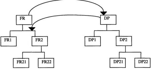
Figure 3-3. Decomposition by zigzagging
The designer follows this approach until he has decomposed the problem to such a point that the solution to the remaining sub-problems is known [6]. Zigzagging is illustrated in figure 3-3.
3.6 Design Matrix
Once all of the design elements have been specified at a particular level in the hierarchy, the relationships among the various elements is defined in a design matrix. The design matrix relates two vectors in two different design domains to each other, either {FR} to {DP) or {DP) to {PV}. Mathematically, the relationships can be written as :
{FRs = [A] * {DPs) for product design {DPs} = [B] * {PVs} for process design
where [A] and [B] are the design matrices. The elements of the design matrix are determined from the following set of equations [12] :
AFRI = (aFRI / aDP1) ADP1 + ... + (aFR1 / aDPn) ADPn
AFRn = (aFRn / aDP1) ADP1 + ... + (aFRn / aDPn) ADPn
where each element in the design matrix is defined as :
Aij = aFRi / aDPj
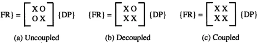
Once a tolerance is specified for the matrix element values, the elements with values over the tolerance can be represented with an "X" while those elements with values below get an "O". This simplification allows the designer to concentrate on the qualitative meaning of the design matrix instead of the quantitative one. For effects that can not be described mathematically, the "X" represents a significant effect while the "0" represents a negligible effect.
To satisfy the Independence Axiom, the design matrix must be either diagonal or triangular. When the design matrix is diagonal, each FR can be controlled independently of the other FRs by its associated DP. This is called an uncoupled design. When the design matrix is triangular, the independence of the FRs can be maintained by imposing an order on the decomposition and change of the DPs. This is called a decoupled design.
Otherwise, the design matrix is considered coupled and independence of FRs is impossible. A coupled design is generally a bad design [13].
FR} = (DP} {FR) = X (DP} {FR) = {DP}
(a) Uncoupled (b) Decoupled (c) Coupled
Figure 3-4. Examples of the three types of design matrices
3.7 Independence Axiom
Axiom 1 Independence Axiom
Maintain the independence of the functional requirements [12]
The first axiom in axiomatic design is the Independence Axiom. It states that the independence of FRs must be maintained in order to achieve good design. Since FRs are by definition independent, any dependence is introduced during the mapping process between FRs and DPs. In order to satisfy the first axiom, the DPs for a given set of FRs must be chosen such that the intrinsic independence of FRs is maintained. The effect of a DP on an FR is described by an element in the design matrix. Only diagonal or triangular matrices satisfy the Independence Axiom. That is why they are referred to as uncoupled and decoupled designs, respectively.
The significance of the Independence Axiom (and the Information Axiom) lies in the significant improvements realized in the performance, robustness, reliability, and
functionality of those designs that satisfy the design axioms [14]. A design which satisfies the Independence Axiom gains a lot in controllability over coupled designs. Since each DP effects only its referent FR, the DPs can be varied independently until all FRs are satisfied. With a decoupled design, the DPs must be varied in a prescribed order to satisfy the FRs. In a coupled design, the FRs can only be satisfied through a complicated feedback sequence which involves most of the DPs at any given time. Although the FRs can be satisfied in a coupled design, the procedure for doing so is much more complex than for those designs which satisfy the Independence Axiom. This conclusion is supported by many case studies presented by the various authors referenced by this thesis.
3.8 Information Axiom
Axiom 2 Information Axiom
Minimize the information content of the design. [12]
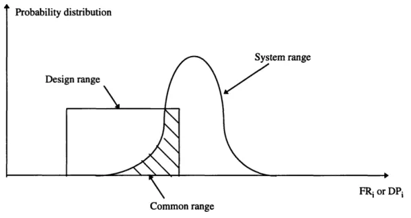
The second design axiom is the Information Axiom. While the Independence Axiom determines the acceptability of a set of possible solutions, the Information Axiom selects the best solution out of the set of acceptable solutions. Axiom 2 states that the "best" solution is the one with the minimum information content. It provides a quantitative means for evaluating design. The information content is defined as the probability a set of DPs will satisfy a set of FRs. Mathematically, the relationship is as follows :
Information = I = log 2 (l/p) = log (system range/common range)
The designer obtains the probability p by examining the graph of the probability distributions of the FR design range and the DP system range for each FR-DP pair. The probability of success for each FR-DP pair is calculated as the area of intersection between the design range and the system range. This area is called the common range. The results are then aggregated to get the overall probability.
DPi Common range
Figure 3-5. Probability distribution functions for FRs and DPs
As the probability p increases, the information content I decreases. To satisfy the
FRs and DPs in his design. This increases the probabilities and decreases the information content.
3.9 Remarks
Axiomatic design theory provides a framework for designers to follow during the design process. Through diligent application of the design axioms, a designer can evaluate the quality of a proposed design in a rational manner that is supported by easily understood analytical results. The axiomatic design process guides designers at all levels of the design, encouraging them to consider alternatives at all levels and to make explicit choices between those alternatives. The axiomatic design method has been successfully applied to industrial practice to support these claims [6, 11].
The work in thesis focuses on the mapping between functional requirements and design parameters and assesses solutions utilizing the design matrix and the Independence Axiom. The work of the other members of the Axiomatic Design Group deals with the remaining aspects of the theory, such as hierarchical decomposition, zigzagging, and the Information Axiom. Please review [6] for more information on the axiomatic design software effort.
Chapter 4. Thinking Design Machine
This thesis project implements a segment of the Thinking Design Machine concept outlined in a paper by Professor Nam P. Suh of MIT and Shinya Sekimoto of the Toshiba Corporation in Japan. In that paper, the concept of an "intelligent machine" or Thinking Design Machine (TDM) is described. The following chapter presents an overview of the TDM concept. Since the Ideation Database is a portion of the TDM concept, it is useful to review the entire system to see where the database fits in. By examining the TDM, the database design developed in the thesis project can be compared against the database schema proposed by Suh.
4.1 TDM Concept
Although many computer aided design tools have been developed, they generally focus on the modeling and drawing portions of the design process. The focus of the TDM is on the early phase of the process, the conceptual design phase. This is where the most critical design decisions are made and where computer automation could yield the greatest benefits in terms of robustness, reliability, and overall quality of the product.
Co
Uncoupled or decoupled
Figure 4-1. Schematic diagram of the TDM [15]
The goal of the TDM is not to assess the early efforts of human designers but to generate creative designs or design concepts which are superior to those currently possible. It uses the axiomatic design method to define, create, and assess design
solutions. Based on the AD principles and focusing on the FR and DP domains
specifically, the TDM performs the following four steps :
Step 1. Definition of functional requirements (FRs) Step 2. Ideation or creation of ideas (DPs)
Step 3. Analysis of the proposed solutions to choose the best solution Step 4. Checking the final solution
In the first step, a preliminary set of functional requirements is defined. In Step 2, the
proposed solutions are then analyzed in Step 3 against the design axioms and other physical constraints. Based on that analysis, the TDM selects the best solution. In Step 4, the TDM checks the final solution against the original customer needs.
4.2 Architecture of the TDM
The architecture of the TDM consists of four modules. Each module corresponds to a step in the TDM concept. Since Step 1, the definition of FRs, is subjective, the software module governing it acts mainly as a check on the work of the designer. It verifies that the requirements are being correctly stated in the functional domain and that they are being defined in a solution-neutral environment. Unfortunately, it is impossible for the system to tell that these constraints are being filled. However, the software can prompt and step the user through the process and alert him to the constraints at the appropriate times. By interacting with the designer in such a manner, the system can attempt to ensure that the constraints are followed.
An ideation software module handles Step 2. By consulting the database, the system finds a plausible set of DPs for each FR being considered. For example, if the FR is "generate power", the system may find some DPs such as "motor", "solar panel", or "windmill". The designer may also propose new DPs for the FRs during this step. The system then creates the design matrices relating the FRs to the plausible DPs.
An analysis software module has the task of determining whether the designs generated by the ideation software are acceptable. If the design matrix is diagonal, the analysis software concludes that it is an acceptable design. If the matrix is triangular, the
software recommends an ordering on the design parameters that will maintain independence of the FRs. If the matrix is neither, then the design might be coupled. The analysis software attempts to reorder the matrix to yield either a diagonal or triangular matrix. If reordering yields neither case, the analysis software identifies possible regions in the matrix for the designer to re-examine.
The last module in the TDM is the system software module. Its job is to verify that the final solution satisfies the original customer needs and to arrange the selected physical components into a working physical system. The sequence of control for the components is dictated by the design matrix. At this point, the TDM would iterate through the process again if it was necessary.
4.3 Database for the TDM
The database is a crucial portion of the TDM. It needs to contain sufficient knowledge to allow it to assist designers by communicating possible solutions. The database should also contain the design knowledge of many designers to give it the largest possible search space with which to synthesize solutions.
In the TDM the FRs and DPs are described and stored as text strings. Once an FR is given, the TDM analyzes the meaning of the FR and searches the database for the corresponding DPs. The search is made through parsing and keyword matching. The database also contains a set of technical terms and their corresponding synonyms,
The knowledge representation of the TDM database is expressed in PROLOG as two types of functions :
fr-dp("FR", ["DPI", "DP2",...])
and
dp-fr("DP", ["FRI", "FR2", ... ])
The functions specify the nature of the relationships between the FRs and DPs. For example, the fr-dp function states that functional requirement "FR" is satisfied by one of the design parameters "DPi", "DP2", etc. The TDM database is essentially a collection of these functions. Although they are interchangeable, the presence of both types of functions in the database increases the probability of finding a new solution [15].
4.4 Remarks
The design and development of the TDM is a long-range goal of the software efforts in the Axiomatic Design Group. To that end, the thesis project focuses on realizing Step 2 of the TDM. The general framework outlined by Suh for the ideation software of the TDM is applicable to the work of the thesis. However, the project follows a different approach in developing the knowledge representation for the database. Rather than incorporate the representation presented in the TDM paper, this thesis develops a new knowledge representation. Chapter 5 describes the new representation.
Chapter
5.
Ideation Database Knowledge Representation
The importance of the knowledge representation to the success of the Ideation Database was recognized early on in the course of the thesis project. Since there was very little consensus in the design community regarding the language of design, the representation needed to deal with the ambiguity before any meaningful work towards systematizing the design process could proceed. In the absence of any particular standards, the development of the knowledge representation focused on supporting the functions of the Ideation Database.
Given a set of functional requirements, the Ideation Database should be able to search its elements for an appropriate set of design parameters to satisfy those requirements. The suggested design parameters should then be analyzed to determine the structure of the corresponding design matrix. This database system should be able to make this determination as efficiently as possible. Additionally, the database needs be extensible, and maintenance overhead should be kept to a minimum.
In order to satisfy these requirements, an effective knowledge representation must be developed to support the database functions. A well-designed representation reduces the overall complexity of the analysis routines in the software at the cost of a little more maintenance overhead for the database. This chapter presents the knowledge
representation developed during the course of the thesis work to support the functions of the Ideation Database system.
5.1 Object Relationships
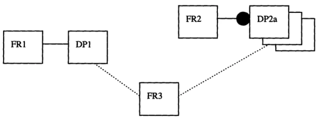
In order to accommodate the requirements of the database, the knowledge representation is constructed using object-oriented methods and consists of two types of data objects : FR objects and DP objects. The FR objects are the primary objects in the
database, and each FR object is linked to multiple DP objects. The DP objects only have meaning with respect to the FR objects. This means that although there may be FR
objects without links to DP objects, there are no DP objects without links to FR objects. Additionally, DP objects are linked only to one FR object although they can effect many other FR objects. This behavior is equivalent to implementing only the fr-dp function types in the TDM. Figure 5-1 presents a graphical example of these relationships.
FR1 DPI
Figure 5-1 illustrates a sample set of objects and their relationships as they would appear in the database. FR1 has a link to DP1, FR2 has links to DP2a, DP2b, and DP2c, and FR3 has no direct links to DPs. However, FR3 does have indirect links to both DP1 and DP2b. These indirect links specify that those DPs effect FR3 even though no direct link between them exists. A direct link between an FR and DP means that the DP satisfies the FR. An indirect link between an FR and DP means that the DP affects the FR. Direct links are defined when a DP is associated with an FR. Indirect links are made at runtime. The way those links are determined is described in section 5.3.
5.2 Object Data Structure
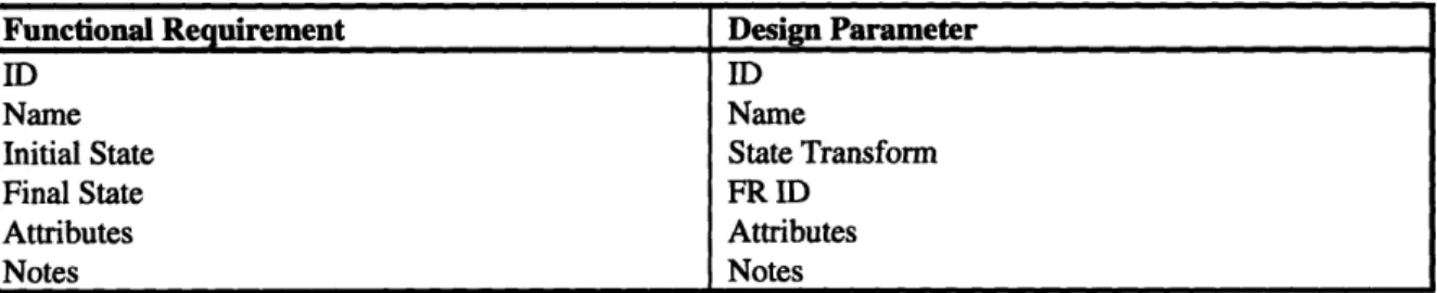
The data structure of the objects can be viewed as an extension to the standard text string method of describing FRs and DPs. Table 5-1 presents the data structure for each type of object.
Functional Requirement Design Parameter
ID ID
Name Name
Initial State State Transform
Final State FR ID
Attributes Attributes
Notes Notes
Table 5-1. Data fields for FR and DP objects
Both objects share a set of common fields. The ID field is a unique numerical identifier assigned and used by the database to identify the object in storage. The Name
field is a text string used to describe the intended behavior of the object. It serves the same purpose as the text strings associated with other FR or DP descriptions. The Notes field is used to store any annotations concerning the object a designer may have.
Unlike the other fields, the Attributes field is really not a field at all. It is a logical bin used to accommodate whatever generic attributes a designer may want to add to an object. Each attribute has fields for a name, value, and type as well as fields for an owner ID and owner type. The name, value, and type fields give the designer the flexibility to define attributes specific to the object. The presence of such attributes further refines the definition of an object. The owner ID and owner type fields identify the object containing this attribute.
What remains are a group of fields specific to the respective objects. The FR ID field in a DP object contains the unique ID of the FR that initially defined the DP. The Initial State and Final State fields of an FR object describe the state of the environment [5] before and after the completion of the function represented by the FR. They may be empty to signify an environment in rest or no effect. The State Transform field of the DP object defines how the DP satisfies the FR and maps to the FR object's Initial and Final State fields. It contains a keyword for each effect the DP object has on the environment.
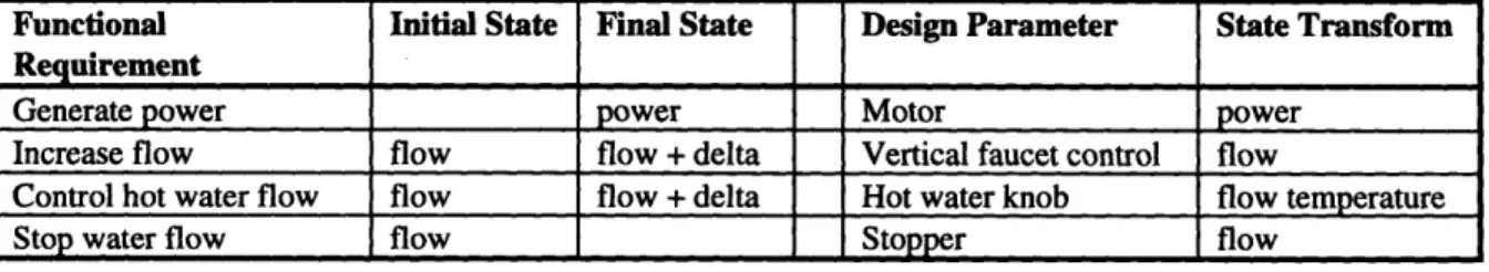
Functional Initial State Final State Design Parameter State Transform Requirement
Generate power power Motor power
Increase flow flow flow + delta Vertical faucet control flow
Control hot water flow flow flow + delta Hot water knob flow temperature
Stop water flow flow Stopper flow
Table 5-2 presents some examples of the state relationships between FRs and DPs.
The descriptions of the fields above serve only as a guideline to their use. The software has no hard-coded requirements on the content of the fields. However, the function of certain fields dictates the format required. For efficiency and correctness, the state fields should only contain keywords. Articles and other extraneous text should be eliminated. None of the other fields in the objects need to adhere to this provision. The reason for the provision is explained in the next section.
5.3 Interaction Model between FRs and DPs
One feature of this knowledge representation which distinguishes it from the standard representation for FRs and DPs is the way effects between those objects are determined. The effects are used to fill in the design matrix for each set of FRs and DPs. In the database of the TDM proposed by Suh, the effects are represented by functions in the database. For example, the function
dp-fr ("gear", ["transmit rotary motion", "change torque", "change revolution"])
defines a relationship between each of the FRs in the list and the DP "gear". If the TDM
needed to determine whether a certain FR was affected by the DP "gear", it would check for the presence of the FR in this dp-fr function.
The main difficulty with using the database of functions as presented by Suh in the TDM paper is in updating the records. In order to be sure that all possible effects are
present in the database, the designer entering a new FR would have to manually traverse the entire database of dp-fr functions, entering the FR into a function when there is an appropriate effect. As the database gets larger, this becomes more and more unrealistic.
As another way to update the database, the designer could elect to make modifications only when a design matrix is presented. The designer would examine the elements of the matrix and make modifications to the database when an element is incorrect. The problem with this method is that, while it is evident that effects are effects (an "X" in the matrix corresponds to a distinct relationship in the database), it is unclear what the situation is when an element in the design matrix is a non-effect (it is ambiguous what the "0" means). That situation is generated in two ways : there really is no effect or the effect has yet to be entered into the database. If it is the second case, the designer simply updates the database and proceeds. However, if the designer determines that it is the first case, there is no easy way to capture the fact that there is no effect in the existing framework. That means that all future designers become burdened with the task of determining that non-relationship as well.
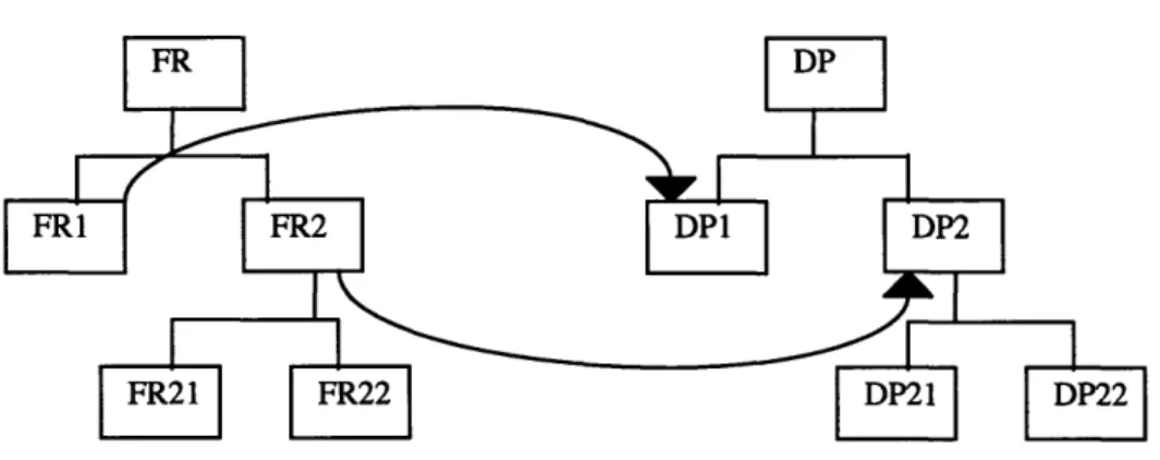
The extension proposed to handle this problem is the use of the state fields described above. When the Ideation Database needs to determine whether there is an effect between a particular FR and DP, it compares the values of the initial and final state fields of the FR against the state transform of the DP. The comparison is made by looking for a match between the keywords of the state transform and the keywords of the initial and final states. This is the reason behind the previously mentioned provision against the use of extraneous words in the state fields. Figure 5-2 illustrates this process graphically.
{FR) = XX {DP}
I xx
Figure 5-2. Interaction model between FR and DP objects
The system uses the results of the interaction model to fill in elements of the design matrix. When the Ideation Database examines design matrix element Aij, it compares the contents of the initial and final state fields of FRi with the state transform field of DPj. If there is a match, the design matrix element Aij receives an "X" to signify the effect. Otherwise, the element receives an "O".
This knowledge representation simplifies the update process. When a new FR is entered, all the designer needs to do is enter the appropriate initial state and final state. The designer no longer has to update all of the affected DPs when entering a new FR. As long as the state fields are defined correctly, the Ideation Database can determine when the FRs and DPs affect each other at runtime by following the interaction model above.
The update process becomes an order(l) routine, an improvement over the order(n) of the TDM function database.
5.4 Remarks
Originally the addition of extra fields into the object data structure was an attempt to provide the Ideation Database system with more keys to search on. By allowing a designer to specify several different attributes for each object, the system reduced the reliance on the description string. During the course of the thesis work, the fact that every designer had his own way of describing things became apparent. Rather than attempt to develop a standard syntax for the description of FRs and DPs, more fields were added to the knowledge representation. This gave the designer more flexibility in defining an FR or DP and gave the software more fields to search for possible matches. However, as the knowledge representation developed, the state elements evolved into key elements in the analysis of effects between FRs and DPs. As mentioned before, the problem with maintaining a list of associated elements for each FR and DP was in updating the records. As discussed above, using the state fields to determine effects at runtime saved a significant amount in system overhead.
Chapter 6. Ideation Database System Architecture
With the knowledge representation as the backbone, this thesis project proceeds to implement the Ideation Database system. This chapter analyzes the design of the system using the axiomatic design method. First, the customer needs are determined. Then, the functional requirements are defined, and the design parameters are chosen. Two level of decomposition are presented.
6.1 Top Level FRs and DPs
According to the axiomatic design method, the first task in the design of the system is the determination of the customer needs. At the highest level, the customer need for the Ideation Database system are :
CN. Assistance for the designer during design process
The customer need specify the attribute desired in the software. To be effective, the
Ideation Database must satisfy this need. A design which provides many useful features
Given the customer need, the following root FR and DP are defined
FR. Assist designer manage design objects DP. Ideation Database system
From the root, the following top-level functional requirements are defined :
FRI. Store and retrieve information FR2. Interact with the designer
The FRs are essentially restatements of the customer needs in functional terms. They describe the functions that the software must provide in order to satisfy the customer need.
To satisfy these requirements, the following design parameters are chosen :
DP1. Database DP2. User Interface
In software, the design parameters represent the modules that are used to satisfy the functional requirements. For the Ideation Database, a database module handles storage and retrieval of design elements, and the user interface module handles presenting information to the designer.
Once the FRs and DPs are chosen for a particular level of the hierarchy, the design matrix can be created. The highest-level FRs and DPs yield the following matrix :
(FR =
XX
{(DPI
The matrix is decoupled. Although the user interface is primarily used to present information to the user, it effects the storage and retrieval of information since it contains the control elements (e.g., the forms and callbacks for data entry) needed to access the database. Since this is a decoupled design, the design parameters must be decomposed in a particular order to maintain independence for the functional requirements. For the Ideation Database, FR1 "Store and retrieve information" should be decomposed first. This fixes the effect of DP1 "Database". Once that effect is determined, FR2 "Interact with the designer" can be decomposed.
6.2 Decomposition of FRI "Store and retrieve information"
The FR "Store and retrieve information" can be decomposed as follows :
FRI.1 Handle basic storage and retrieval FR 1.2 Handle queries for information
These FRs are chosen given the DP "Database". If another DP had been chosen to satisfy FR1, the decomposition would be different.
DP1.1 Dynamic Data Exchange (DDE) DPI.2 Structured Query Language (SQL)
The two DPs are both specific to a database. Rather than considering these sub-DPs as just the decomposition of the parent DP "Database", they are the reflection of the choice of FR as well. An FR alone or a DP alone does not determine the decomposition. It is the two together that determines the elements of the next level.
At this level, the design matrix is :
{FR} = OX
{DP}
This is an uncoupled design. The work of DDE does not affect how SQL interacts with the database. More information about DDE and SQL can be found in [10]. Decomposition stops here since DP1.1 and DP1.2 are both leaves.
6.2 Decomposition of FR2 "Interact with the designer"
Since the design matrix at the previous level was coupled, the value of DP1 "Database" had to be determined before FR2 could be decomposed. With FR1 decomposed and DP1 determined, FR2 can be decomposed with the structure of the database as a constant.
FR2.1 Present database information to the designer FR2.2 Assist designer in analyzing requirements
In addition to being affected by the choice of FR2 and DP2, the two functional
requirements at this level are also affected by the result of the decomposition of FR1 and DP1. The coupled nature of the top level design matrix is evidence to this fact. Since
FRI and DPI were decomposed first, the two sub-FRs at this level can be defined taking
the result as a given.
The DPs for these FRs are :
DP2.1 Database View DP2.2 Analysis View
These two DPs define the two main modules of the user interface. Unlike the two sub-DPs for DP1 which are leaf nodes, the implementation of these two sub-sub-DPs is unclear at this point. Further decomposition (which will not be shown here) is necessary.
At this level, the design matrix is :
{FR} = [X {(DP)
The decomposition of DP2 is also uncoupled. Therefore, the design and decomposition of both modules of the user interface can continue independently and in parallel.
6.3 System Hierarchy
The decomposition above results in the following system hierarchy in the FR and DP domains:
Figure 6-1. System hierarchy for the Ideation Database
The ghost boxes represent further decomposition not presented here.
6.4 Remarks
By analyzing the architecture of the Ideation Database using the axiomatic approach, two things are gained. The validity of the axiomatic approach in software design is demonstrated and the decision-making process governing the design of the system is documented.
Axiomatic design provides a rational framework to a software design process traditionally dominated by trial-and-error methods. It also provides a better design
documentation structure than other software design methods such as Object Modeling Technique (OMT) and IDEFO which focus mainly on program flow and structure. Following the axiomatic approach, the designer can determine the rationale for a particular design as well as the recommended structure of data flows [14].
![Figure 3-1. Design domains [6]](https://thumb-eu.123doks.com/thumbv2/123doknet/14680086.559053/30.918.195.695.408.590/figure-design-domains.webp)
![Table 3-1. Analogy among different design problems [14]](https://thumb-eu.123doks.com/thumbv2/123doknet/14680086.559053/31.918.123.798.360.702/table-analogy-different-design-problems.webp)
![Figure 4-1. Schematic diagram of the TDM [15]](https://thumb-eu.123doks.com/thumbv2/123doknet/14680086.559053/42.918.174.748.105.457/figure-schematic-diagram-tdm.webp)