Design and Manufacturing of a VTOL Micro Aerial Vehicle
by Neil R. Gupta
S.M. Mechanical Engineering
SUBMITTED TO THE DEPARTMENT OF MECHANICAL ENGINEERING IN PARTIAL FULFILLMENT OF THE REQUIREMENTS FOR THE DEGREE OF
MASTER OF SCIENCE IN MECHANICAL ENGINEERING AT THE
MASSACHUSETTS INSTITUTE OF TECHNOLOGY JUNE 2001
© 2001 Neil Gupta. All rights reserved.
MASSACHUSETTS INSTITUTE OF TECHNOLOGY
iUL 16 2001
LIBRARIES The author hereby grants to MIT permission to reproduce and distribute publicly paper
and electronic copies of this thesis document in whole or in part.
Signature of Author
3ARKER
IDepartment of Mechanical Engineering
Certified b,
/ John M. Plump
Charles Stark Draper Laboratory Thesis Supervisor Certified by
Prof. Samir Nayfeh Assistant Professor Thesis Advisor Accepted by
Professor Ain A. Sonin Chairman, Departmental Graduate Committee /
Design and Manufacturing of a VTOL Micro Aerial Vehicle
byNeil R. Gupta
Submitted to the Department of Mechanical Engineering on March 9, 2001 in partial fulfillment of the requirements for the Degree of Master of Science in Mechanical
Engineering. Abstract
The miniaturization of electronic guidance and navigation systems has opened a new frontier in aviation. The opportunity now exists to develop miniature aerial vehicles capable of autonomous flight. Such vehicles could perform reconnaissance missions in environments that are unsafe to humans. Their small size minimizes their chance of being detected in hostile areas and allows them mobility not afforded by typical full size vehicles and humans.
The purpose of this thesis was to develop a 10" VTOL Micro Aerial Vehicle capable of high-speed forward flight. The innovative design incorporates a pair of counter-rotating, variable pitch propellers enclosed in a protective duct structure. Independent control of propeller pitch provides thrust and yaw control for the vehicle while in a hover mode. Translational control is provided by four independently actuated control surfaces which are placed in the area of high-speed flow aft of the propeller disks. In its forward flight mode, the duct acts as the primary lifting surface and the control surfaces act as movable canard wings. Power is provided by an off the shelf 0.25 cubic inch displacement 2-stroke glow-fuel engine. A volume of 9 cubic inches has been set
aside in the main fuselage to house the Draper Micro Electromechanical integrated navigation package. A payload sensor bay with a volume of 3 cubic inches has also been incorporated into the design.
Initial tests of this vehicle configuration indicate that it is a mechanically feasible design, which produces close to 75% of the thrust required to hover. Further development will focus on design refinements to create a lighter, more robust mechanical drive train, and aerodynamic analysis that will guide the redesign of the propeller.
Technical Supervisor: Mr. John M. Plump Title: Senior Member of the Technical Staff
Thesis Advisor: Professor Samir Nayfeh Title: Professor of Mechanical Engineering
ACKNOWLEDGMENT June, 2001
I would like to thank all those involved in completion of this thesis: To The Draper Labs, for providing me with this unique experience and a productive learning environment. I would like to thank Ed McCormack and John Mahoney of the machine shop for their great mechanical intuition and experience and to Pete Kerrebrock for his expertise and enthusiasm. Thank you to Kyrilian Dyer for all those long hours, late nights, and scary time standing behind a spinning propeller blade. To Paul Eremenko and Sean George for invaluable advise and great friendship. I would especially like to thank my advisor John Plump for trusting me with a great responsibility. It has been an honor to work with you, your humor and encouragement have kept me motivated through all the technical problems along the way. Of course I would also like to thank my family, Mom, Dad and Olaina who have always stood by me. You've helped me achieve and become the person I am.
This thesis was prepared at The Charles Stark Draper Laboratory, Inc., under Internal Company Sponsored Research Project 3019, Navigating Under the Canopy.
Publication of this thesis does not constitute approval by Draper of the findings or conclusions contained herein. It is published for the exchange and stimulation of ideas.
Contents
1 INTRODUCTION
1.1 Customer Needs statement
1.2 Industry overview
2 VEHICLE CONCEPT DEVELOPMENT
2.1 System requirements
Physical requirements
Performance requirements
2.2 Analysis of existing technology
2.3 Conceptual Layout
2.4 Conceptual Operation
3 PRELIMINARY VEHICLE DESIGN
3.1 Feasibility Analysis
3.2 Helicopter Rotor Dynamics Rotor Torque
Rotor Model Results
3.3 Preliminary Design Airframe Drive Train Control Surfaces 14 14 19 22 22 22 22 23 26 27 30 30 31 35 35 36 36 37 37
Composite Structures
3.4 System Modeling 39
Control Dynamics 40
Basic Geometric Layout 40
Model Parameters 42
Control Model Results 43
3.5 Horizontal Flight Analysis 44
3.6 Summary 47
4 ALPHA DESIGN CYCLE 48
4.1 CAD Design 48
Airframe 49
Drive train 50
Computational Validation 54
Variable pitch mechanism 57
Control Surfaces 62
4.2 Weight and balance issues 63
5 MANUFACTURING 68 5.1 Composite Design 68 Factors 68 Lessons Learned 70 5.2 Mold Design 72 Lessons Learned 74 39
6 TESTING
6.1 Ducted rotor tests
6.2 Electric motor tests
6.3 IC engine tests
7 BETA DESIGN
7.1 Integrated inner duct
7.2 Composite fore body
7.3 Pod redesign 7.4 Drive train 7.5 Future Work 8 CONCLUSION 8.1 Lessons Learned 76 76 78 79 86 86 87 88 89 91 94 94
List of Figures
FIGURE 1-1 MAV DEPLOYMENT FROM CASCADING "PARENT CHILD" SYSTEM 16
FIGURE 1-2 MAV USE IN URBAN SETTING 17
FIGURE 1-3 MAV USE IN RURAL SETTING 18
FIGURE 1-4 VEHICLE CLASSIFICATION SCALES 19
FIGURE 2-1 SIKORSKY VS-300 (1939) 23
FIGURE 2-2 CYPHER 24
FIGURE 2-3 MICROSTAR 24
FIGURE 2-4 BLACK WIDOW 24
FIGURE 2-5 MICRO CRAFT VTOL VEHICLE 25
FIGURE 2-6 CONCEPT VEHICLE OPERATION AND LAYOUT 26
FIGURE 3-1 MASS PERCENTAGES 31
FIGURE 3-2 PROPELLER INDUCED VELOCITY 33
FIGURE 3-3 VARIABLE PITCH MECHANISM 37
FIGURE 3-4 FLOATING ACTUATOR 38
FIGURE 3-5 CANARD REINFORCING SPAR 39
FIGURE 3-6 CONCEPT VEHICLE LAYOUT (DUCT REMOVED) 41
FIGURE 3-7 SCHEMATIC DYNAMIC FORCE DIAGRAM 42
FIGURE 3-8 (6) DEGREE CONTROL DEFLECTION 44
FIGURE 3-9 (37) FT/S CONSTANT INFLOW VELOCITY 45
FIGURE 4-1 PRELIMINARY ALPHA CONCEPTUAL LAYOUT 48
FIGURE 4-2 ALPHA DESIGN AIRFRAME 49
FIGURE 4-3 FORE BODY PODS 50
FIGURE 4-4 PRELIMINARY DIFFERENTIAL GEARBOX DESIGN 51
FIGURE 4-5 REVISED ALPHA GEARBOX DESIGN 52
FIGURE 4-6 HTD BELT STRESS CONCENTRATIONS 53
FIGURE 4-7 EPS, HTD BELT SELECTION TABLE 53
FIGURE 4-9DIRECTIONS OF FORCES ON GEAR MESH 56 FIGURE 4-10 CUT-AWAY VIEW OF VARIABLE PITCH MECHANISM 58 FIGURE 4-11 ISOMETRIC VIEW OF VARIABLE PITCH MECHANISM 59
FIGURE 4-12 EXPLODED VARIABLE PITCH ACTUATOR 60
FIGURE 4-13 FOUR BAR MECHANISM 61
FIGURE 5-1 FOUR DUCT DESIGN ITERATIONS 70
FIGURE 5-2 (0-90) WEAVE 71
FIGURE 5-3 TWILL WEAVE 71
FIGURE 5-4 SILICONE TUBE FOR VACUUM ARRANGEMENT 72
FIGURE 5-5 MULTI-PART MOLD 73
FIGURE 5-7 URETHANE MALE MOLD INSERT 75
FIGURE 6-1 ELECTRIC MOTOR THRUST TEST SETUP 77 FIGURE 6-2 VERTICAL ELECTRIC MOTOR THRUST TEST SETUP 79
FIGURE 6-3 TWO MASS OSCILLATING SYSTEM 80
FIGURE 6-4 IC ENGINE DUCTED TEST STAND 81
FIGURE 6-5 THRUST VERSUS RPM FOR VARYING UPSTREAM COLLECTIVE SETTINGS
(UNDUCTED) 83
FIGURE 6-6 TYPICAL MODEL IC ENGINE PERFORMANCE CURVES 85
FIGURE 7-1FUEL TANK CUT-AWAY VIEW IN DUCT 87
FIGURE 7-2 FORE BODY MOLD 88
FIGURE 7-3FORE BODY ASSEMBLY 89
List of Tables
TABLE 2-1 DESIGN CONCEPTS 26
TABLE 2-2 COMPOSITE DESIGN CONCEPT 27
TABLE 3-1 COMPONENTS 31
TABLE 3-2 ADVANCE RATIOS 34
TABLE 4-1 LEWIS FACTOR ANALYSIS CASE 56
TABLE 4-2 GEAR FORCE AND PRESSURE RESULTS 57
TABLE 4-3 STRUCTURAL WEIGHT DISTRIBUTIONS 65
TABLE 4-4 PROPULSION AND AVIONICS WEIGHT DISTRIBUTIONS 66
TABLE 4-5 PAYLOAD DISTRIBUTION AND TOTAL CG CALCULATION 67
1 Introduction
From the conception through construction of the Perching Unmanned Aerial Vehicle (PUAV) project, much knowledge and insight has been gained in the specifics of miniature scale aeronautical systems. The technical hurdles ranged control surfaces sustaining low Reynolds numbers and bi-directional flows, to high drive train rpm's and material strength and weight issues. This paper will attempt to convey the design methodology involved in the evolution toward a complete vehicle system.
1.1 Customer Needs statement
The ever-changing global political environments around the world today have created a variety of new tactical battle needs. To modernize the role of the typical foot soldier, the US armed forces seek to increase the information available to individual soldiers on the battlefield. Part of this vision includes the use of Micro Aerial Vehicles (MAVs) that would be carried by soldiers. In order for our troops to operate safely in hostile areas that are nowadays more often urban, small surveillance craft are needed. These vehicles would allow ground troops to inspect an area for chemicals, explosives or hostile personnel before humans move into it. Their small size would reduce their chances of being detected, and allow them access to spaces that their full scale counterparts could not access. Small surveillance craft would also allow foot soldiers to familiarize themselves with the area while they are out of harm's way. This could include recognizing landmarks, understanding civilian movements and visualizing expected terrain. Alternative missions scenarios for MAVs could include surveillance and remote sensing with the MAV being deployed from a series of larger, "parent" autonomous vehicles.
Currently several medium to full scale autonomous vehicles are deployed in combat situations. However, there are several limitations to these designs. The US armed forces states that the biggest improvements need to come in the areas of real time, "timely intelligence gathering" and range/duration improvements . MAVs present the ability to produce timely intelligence gathering by their proximity to the operating troops. Unlike large scale remotely piloted vehicles, MAVs require very little logistical support and the data they gather is on the front line where events can change rapidly. Particularly VTOL MAVs present the opportunity to stop and "perch" during a mission to gather intelligence on a particular area in detail.
Because these MAVs would be used in hostile environments their survivability and usability must be very high. The vehicle structure must be tough and durable, while the physical system itself retains a high degree of usability. It is desired that the final product be usable by any untrained field soldier. At the time of vehicle conception the Draper Laboratory had defined some basic outlines for such a vehicle, they were:
0 10 inch maximum linear dimension 0 VTOL capability
0 20 minute flight duration 0 Camera video down-link
0 Capable of hovering flight in winds less than 5 mph
Parent UAV
I Km 100 Kmi1 Km
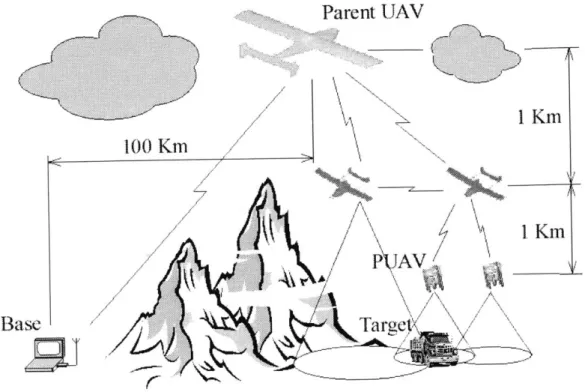
\/P AV BaseFigure 1-1 MAV deployment from cascading "parent child" system
One MAV operating scheme in the context of an overall military operation is shown in Figure 1-1. The vehicle is deployed as part of a cascading series of autonomous vehicles. Here the MAV acts as a continued extension of a battle groups arms providing finer detailed information at a much more local level. Presently, reconnaissance information obtained by battle group commanders often takes too long to get to the individual foot soldiers, or is not given at all. The MAV would provide local reconnaissance information to the forward deployed units of the battle group, helping to complete the dissemination of knowledge.
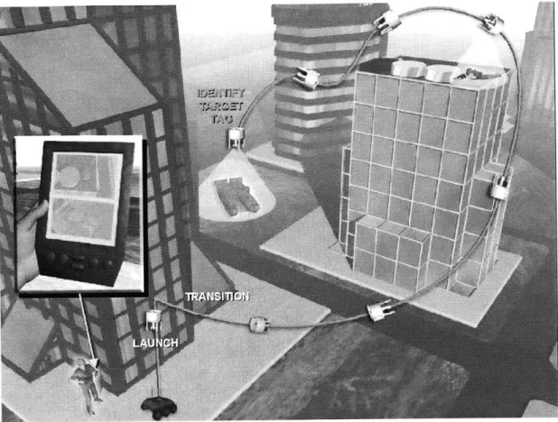
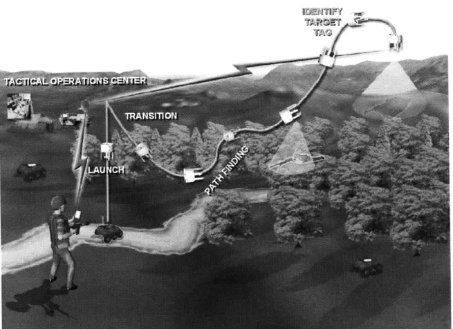
At the troop level the MAV can be used in both urban and rural settings as shown in Figure 1-2 and Figure 1-3.
Figure 1-3 MAV use in rural setting
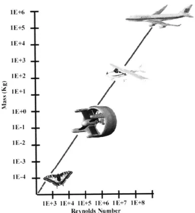
Typically a MAV is described as a being 10-6 times less massive than a full scale aircraft as can be seen in Figure 1-4. This figure also displays one of the major contributors to the complexity of MAVs. The lower axis shows how the Reynolds number scales with the size of the vehicle. As the order of magnitude drops dramatically, the flow regime will be significantly different from those seen on full size aircraft. This can necessitate the use of different airfoils, and cause other undesired aerodynamic characteristics such as boundary layer separation, or unsteady flows.
1E+6 1E+4 IE+3 1E+2 1E+1 IE-1 I E-2 IE-3 IE-4
1E+3 1E+4 1E+5 1E+6 1E+7 1E+8 Reynolds Number
Figure 1-4 Vehicle classification scales
1.2 Industry overview
Although computer guidance systems have been in use since the days of the Apollo program, it was not until the age of miniature electronics that they became widespread. The advancement of miniature navigation hardware, gyroscopes and accelerometers as well as the widespread use of GPS has enabled a trend toward smaller autonomous vehicles. However aerodynamics do not simply scale with the size of the aircraft, and the configurations of such vehicles have become less traditional in the attempt to improve their capabilities. The small size of these vehicles also increase the frequency of their dynamic modes making oscillations or response to disturbances often orders of magnitude faster. Consequently many of these vehicles need computer control systems to be stable in flight.
The past ten years have seen several MAVs with a wide range of configurations, sizes and mission requirements. Some military contractors have developed prototype
MAVs as demonstrators. Lockheed Martin Aeronautics pioneered a fixed wing MAV called Black Widow. This design has been popularized in the university MAV competitions and was used by the University of Notre Dame. The US Navy developed fixed wing vehicles such as Bluebird and then began to experiment with VTOL capabilities with their AROD and Arkytas vehicles. Micro Craft of San Diego is in the process of building a small ducted vehicle with VTOL capabilities. This concept is based on a General Dynamics design dating back to 1958.
2 Vehicle Concept Development
2.1 System requirements
The challenge of this project was to develop a MAV that met the needs of the military defined by The Draper Laboratory. A balanced design approach was used to address multiple layers of complexity in parallel. Vehicle robustness and usability were considered, with gross weight and system complexity balanced with the desired capabilities.
Physical requirements
Basic size requirements were dictated by the Military's needs for a surveillance aircraft that could be carried with the standard issue equipment of a foot soldier and used without special training. The vehicle was to be capable of fitting in a ten inch cube. Although weight was not a specific factor it is apparent that the necessity to remain light is driven by the challenge of the vehicles hover capability. Power plant type and configuration were not specified allowing for the exploration of several options.
Performance requirements
A typical flight duration of between 10-20 minutes was required. Twenty minutes was seen as the final goal with ten minutes being an achievable prototype duration. The vehicle must be capable of vertical take off and landing as well as flying rapidly from one location to the next. This was interpreted as the ability of the vehicle to transition between a dash (40+ mph horizontal flight) and loiter flight mode. The vehicle would therefore have two distinct flight modes, and not a third "perturbed hover" mode that is a transitional phase between the two extremes. The vehicle defined at this stage would
consist of only flight capable hardware, no autonomy and control issues were to be addressed at this time.
2.2 Analysis of existing technology
Vertical Take Off and Landing (VTOL) aircraft are not uncommon in the aerospace industry. In their most basic form (the balloon) they have been in existence even before the airplane. As part of the initial design conceptualization, a specific effort was made to asses all approaches to VTOL technology. It was important to start the design from the ground up considering every possibility. This would allow for the coalescence of the best alternatives.
Several existing VTOL designs were considered to glean the best characteristics from each. The most common examples of VTOL aircraft are helicopters, although even these come in many different forms. The VS-300 flown by Igor Sikorsky in 1939 (Figure 2-1) was a single rotor aircraft with a tail rotor to counter-act the torque produced by the main rotor.
Figure 2-1 Sikorsky VS-300 (1939)
The Russian Kamov design bureau is famous for its contra-rotating propeller designs that eliminate the need for a tail rotor. Helicopters are true VTOL vehicles and
have exceptional maneuvering characteristics, but their horizontal speed is much less fuel efficient than fixed wing aircraft. To compensate for this lack of efficiency, tilt-rotors and tilt-wings have been built. These combine the VTOL and maneuvering capabilities of the helicopter with the horizontal flight speed and range of a conventional aircraft. Unfortunately this often involves complex mechanisms and aerodynamics.
Figure 2-2 Cypher Figure 2-3 Microstar
An overview was done of existing Unmanned Aerial Vehicles (UAVs) and MAVs. Since the late seventies there have only been a few VTOL capable UAVs built. Some of these include the Cypher (Figure 2-2), QH-50 and CL 327. Several versions of Non-VTOL MAVs have been built, including Lockheed Martin's Microstar (Figure 2-3) and a Aero Virenments Black Widow (Figure 2-4).
There have also been attempts at transitioning ducted vehicles. Micro Craft of San Diego, California is in the process of developing a transitioning ducted fan vehicle that will use the duct as a wing in horizontal flight. The genesis of this transitioning VTOL concept dated back to an unmanned vehicle built by General Dynamics in 1958 (Figure 2-5).
Figure 2-5 Micro Craft VTOL vehicle
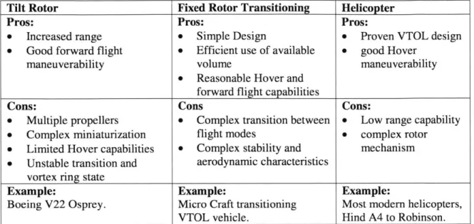
Positive and negative system characteristics were extracted during the overview of these existing technologies. The results are summarized in Table 2-1. This condensation helped outline the possible directions that VTOL design implementation could go. The high level mapping allowed informed decisions to be made as to the basic avenues to be considered. This assured that the final design would be well grounded, and helped to keep in perspective past lessons learned.
Table 2-1 Design Concepts 2.3 Conceptual Layout Thrustj flover
*4 Trariion
manefluver:I Horizontal FlightFigure 2-6 Concept vehicle operation and layout
The overarching concepts were weighed and combined to create a composite design. The basic vehicle shape and operational concept can be seen in Figure 2-6. The
Thrust
Tilt Rotor Fixed Rotor Transitioning Helicopter
Pros: Pros: Pros:
* Increased range 0 Simple Design 0 Proven VTOL design * Good forward flight 0 Efficient use of available 0 good Hover
maneuverability volume maneuverability
0 Reasonable Hover and forward flight capabilities
Cons: Cons Cons:
* Multiple propellers 0 Complex transition between 9 Low range capability * Complex miniaturization flight modes 0 complex rotor * Limited Hover capabilities 0 Complex stability and mechanism * Unstable transition and aerodynamic characteristics
vortex ring state
Example: Example: Example:
Boeing V22 Osprey. Micro Craft transitioning Most modem helicopters, VTOL vehicle. Hind A4 to Robinson.
compiled characteristics of this design are listed in Table 2-2. This design concept was then fleshed into a block layout that incorporated all the characteristics listed in the table.
Table 2-2 Composite design concept
2.4 Conceptual Operation
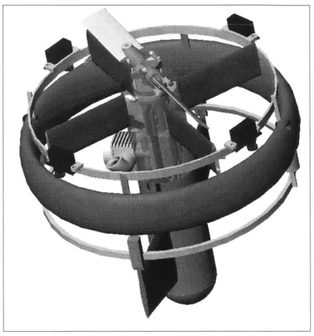
The resulting vehicle was a marriage of several proven design technologies. It incorporated a toroidal outer shell that would act both as a ring wing in horizontal flight, a duct for improving propeller thrust in hover, and a rotor guard for safe in-field operations. The concept of variable collective pitch would be borrowed from helicopter design to give variable thrust at constant engine rpm and the ability to reverse thrust direction. Keeping engine rpm constant is especially important with small two-stroke engines which are optimized for a narrow bandwidth of operational speeds. Control surfaces downstream of the propeller down-wash would enable translation during hover, and would act as canards during horizontal flight. Maneuvering from one flight mode to
PUAV Pros:
" Transitioning vehicle with limited
helicopter thrust augmentation * Capability to alter blade angle for
forward flight efficiency and hover speed
* Ducted rotor for increased flight range and operator safety
Cons:
* Increased mechanical complexity due to collective
" Complex stability and aerodynamic
characteristics Example:
Final configuration of fixed ducted vehicle with ability to change thrust direction and flight mode
another by means of thrust reversal is aggressive and more complex, however it allows for a fast transition between flight modes, seen as a boon in hostile environments.
3 Preliminary Vehicle Design
The conceptual layout developed in chapter two was then detailed on several levels outlined in the following chapter. The feasibility of each major design decision is supported by simulation or analysis whenever possible.
3.1 Feasibility Analysis
A preliminary feasibility analysis was performed on the vehicle concept in its early stages. This ensured that the rough estimate sizes and components under consideration would be reasonable choices. To reduce the time and complexity of building a prototype, off-the-shelf technologies were implemented wherever possible. The model hobby industry supplied much of the basic hardware that would otherwise require considerable re-development time. Stock model two-stroke engines were considered along with electric motors. A preliminary overview of the power density available for each propulsion method indicated that electric motors would require a prohibitively large battery pack for sustained flight. Model engines in the size range of
.15 cid to .32 cid were considered for their relatively small size and power output in the
range of 400-650 watts (.5-.85 bhp).
Other stock items to be used were RC radio receivers, servo actuators, NimH batteries and model helicopter rotor assembly parts. A review of the market was done to select the smallest lightest components that would perform adequately. A summary of the components selected is in Table 3-1. Figure 3-1 below is a graphic showing the percentage of total vehicle weight that each element represents.
Table 3-1 Components
Figure 3-1 Mass Percentages
Canard Servos 3% Vehicle Structure 24% Variable Pitch Mechanism 15% Batteries 5% Micro Servo 1% Receiver 1% Fuel 32% Engine 22% Total: 1,135 grams
3.2 Helicopter Rotor Dynamics
The PUAV design had a simple two bladed unhinged rigid rotor capable of collective pitch adjustments. Because of the rotor's small radius (.120m, (4.73inches)) it was possible to make the assumption of a rigid, untwisted blade, greatly simplifying the
Component Qty Part Weight (grams) total weight
6 Servos 4 S-90 (FMA) 9.07 36.28
Micro Servo 2 LS-3.0 3 6
Receiver I Tetra FM (FMA) 14.17 14.17
Fuel (20 min dur.) 1 380 ml 380 380
Engine 1 .25 FX (OS) 249.47 249.47
Batteries 3 Lithium Rec. Bat 20 60
Variable Pitch Mech. 1 1 90 90
Vehicle 1 structure 300 300
analysis. It was intended that accurate simulation of the single rotor model would enable proper design of the control surface scheme necessary for flight control. Coupled with the simulation of these control surfaces and the aerodynamics of the vehicle body itself a complete simulation would be achieved allowing for the implementation of initial control algorithms.
Basic Momentum theory and Blade Element theory were employed to derive expressions for the rotor induced velocity and power. Most schemes express the induced velocity as a function of propeller thrust and visa versa" leading to an iterative solution. The desire in this simulation was to develop a rotor model that was both accurate to the ducted design, and able to predict multiple configurations (i.e. reverse collective pitch). The result is a hybrid of blade element theory and use of lookup tables generated by X-Rotor software
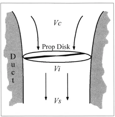
As shown in (Figure 3-2),The propeller induced velocity V, is the sum of the incoming air relative velocity V, and the air velocity at the propeller disk Vi.
Figure 3-2 Propeller induced velocity
The velocity at the propeller disk is calculated from:
_i TNge
V=2pA
Where Nge is the Ground effect parameter defined as :
1
Nge
= + 2 1+Kge ) VcProp Disk
Vi
lVs
Eq. 3-1 Eq. 3-2Here Kg, is the ground effect parameter and its value is .125, and the altitude of the craft is given by h.
In order to obtain a non iterative solution for Thrust, X-rotor was utilized to generate a table of CT values for varied advance ratios and collective pitch settings. The Preliminary PUAV rotor design was input into X-rotor and the program run for a range of propeller rpm's form 4,0000 to 15,000 and several craft vertical velocities. The assignment of rpm and vertical velocity individually allowed for the definition of specific advance ratios. This prohibits the X-rotor program from creating unreasonable rotor rpm's in the case where only an advance ratio is defined. Rotor rpm's to be simulated were chosen from the expected capabilities of the model engines rated at 4,000-18,000 rpm. Data was extrapolated into large advance ratio regimes. A truncated version of the current CT Vs. y and Q table is shown in Table 3-1.
Table 3-2 Advance ratios
Advance Ratio
Collective -6.OE+00 -2.OE-02 -2.OE-04 4.5E-06 2.4E-04 2.OE-02 2.OE+00 8.OE+00
0 0 0 0 0 0 0 0 0
2 3.1E-04 4.7E-03 6.3E-03 7.9E-03 8.OE-03 8.7E-03 9.1 E-03 8.8E-03 4 4.2E-02 3.3E-02 2.9E-02 2.6E-02 2.3E-02 2.4E-02 2.3E-02 2.0E-02
6 8.3E-02 6.1E-02 5.2E-02 4.4E-02 3.8E-02 4.OE-02 3.8E-02 3.OE-02 8 1.3E-01 8.9E-02 7.5E-02 6.2E-02 5.3E-02 5.5E-02 5.2E-02 4.1 E-02 10 1.7E-01 1.2E-01 9.8E-02 8.OE-02 6.8E-02 7.1E-02 6.6E-02 5.2E-02 12 2.1E-01 1.4E-01 1.2E-01 9.8E-02 8.3E-02 8.6E-02 8.1E-02 6.3E-02 14 2.1E-01 1.9E-01 1.8E-01 1.7E-01 1.6E-01 1.7E-01 1.7E-01 1.3E-01
The advance ratio y is defined as:
r = Eq. 3-3
T = fpCT)fD q. 3.4
In this manner the iterative formulation problem was overcome. The continued development of an accurate CT table will enable reliable rotor predictions to be made.
Rotor Torque
An expression for rotor torque was developed from blade element theory'. This begins with a formulation of rotor coefficient of power. This includes terms for both profile drag and induced drag on the rotor. The rotor coefficient of power is derived as:
UCd
kCT
C =
+)
Eq.3-58
-vF
Where Cd is found from a lookup table of Cd versus Collective pitch angle of attack. Power is then defined as :
P
=2
(Vi)
pCpR
2 Eq. 3-6Vtip is the rotor tip velocity in meters per second.
Finally Torque is found from:
P
V Eq. 3-7
Rotor Model Results
The completed rotor model was capable of predicting thrust, induced velocity and torque for any applicable rotor rpm and positive collective pitch settings. Reverse collective pitch settings could later be studied in order to implement transition of the vehicle into horizontal flight. The results framed an expected induced velocity range that could be applied to the control surface model to predict the control force necessary to
counteract the torque produced by the spinning rotor. At the expected engine rpm under load (12,000) the simulation produced a propeller induced velocity of 30-40 ft/s with collective pitch deflections of 10-15 degrees. The predicted thrust for this operating regime was 1.25 Kg. With a vehicle weight estimate of 1.13 Kg the vehicle would have a margin of 10% for translation maneuvers in hover.
3.3 Preliminary Design
In the proceeding section the preliminary design will be presented in stages. Each stage is critiqued and the technical issues encountered during design and manufacturing are discussed.
Airframe
Using the basic design outline generated from the trade study a preliminary vehicle design was created. The primary goal was to keep the drive train simple by using only one variable pitch propeller. It was conceived that the torque generated by the rotor could be counteracted by the stators inside the duct. With the drive train in line with the axis of the vehicle the structural concept was to link a rigid center body to a strong outer duct. Although the outer duct needed to be rigid, it still needed to be as light as possible. In an effort to use heavier structural components only where needed, it was determined that the inner surface of the duct should be separate from the outer surface. Composite materials, (preferably carbon fiber) would be used wherever practical. Therefore the inner surface could be made thicker and reinforced with stringers in the fore and aft. The thin pliable outer shell would then provide only the shape of the airfoil in horizontal flight. It would slip on and off to provide access to internal fuel tanks and servos.
With an estimated diameter of 25.4 cm (10 inches) and a span of 15.24 cm (6 inches) the surface area of the duct would be approximately 774 square cm. The thickness of a single layer of carbon fiber was measured at .76 mm (.030 inches) resulting in a duct material volume of 59 cubic cm. Assuming a composite lay-up with 70% fiber and 30% matrix by volume, the density of the duct carbon material was estimated as 1.64 grams per cubic centimeter. This density multiplied by the estimated duct volume gave a theoretical duct weight of 97 grams. This value was well within the target weight of 180 grams.
Drive Train
An initial concept for a single propeller variable pitch mechanism that fit directly over the engine was constructed. The goal was to use off the shelf hardware wherever possible and keep the parts as small as possible. The initial design borrowed heavily from existing tail rotor designs on RC
helicopters. Figure 3-3 shows a CAD model of the mechanism. Torsional stiffening rods were placed along the
sides of the mechanism to help carry i the load from the rotor hub to the
actuation ring.
Figure 3-3 Variable pitch mechanism
Control Surfaces
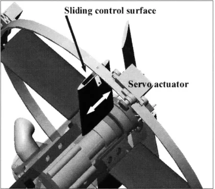
Directional control of the vehicle would be provided by the four movable control surfaces inside the duct. These could be biased to take out the torque of the spinning
rotor blades and directional control could be applied over that. In forward flight the canards would aid in the production of lift, while the internal control surfaces acted like rudders and elevators. These surfaces would be mounted on a sliding surface so that their center of pressure coincided with the actuation axis during both forward flight and hover flight. (Figure 3-4) They would switch configuration due to the change in pressure drag force direction in hover and forward flight modes.
Sliding control surface
...
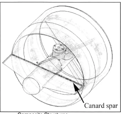
Canard spar
Composite Structures
Figure 3-5 Canard reinforcing spar
The center body of the aircraft would be supported at one end by the control surfaces and at the other end by the canard. The reaction torque from the rotor would be transferred through the canard into the duct. Therefore the canard structure should be reinforced. The preliminary design would employ a reinforced rib structure in the canard that carried across the length of the vehicle (Figure 3-5). These spars and ribs would be made out of balsa wood with carbon as the outer shell.
3.4 System Modeling
To gain an understanding of the flight dynamics of the vehicle a system simulation was undertaken. Many other VTOL MAVs use only one propeller and incorporate stator vanes to counter-act the torque of the rotor. In order to properly size the control surfaces
a simulation of the aerodynamic forces was developed. At the same time this model helped to determine the maximum thrust that could be expect from the rotor blades.
Control Dynamics
In this design configuration four control surfaces internal to the duct were used to control Roll, Pitch and Yaw. It was desired that these control surfaces act as control surfaces as well as stator vanes to take out the rotational torque of the spinning rotor. As a preliminary design guide to the feasibility of this approach, a control surface model was developed to predict the torque that could be produced downstream of the propeller induced velocity by control vanes.
Basic Geometric Layout
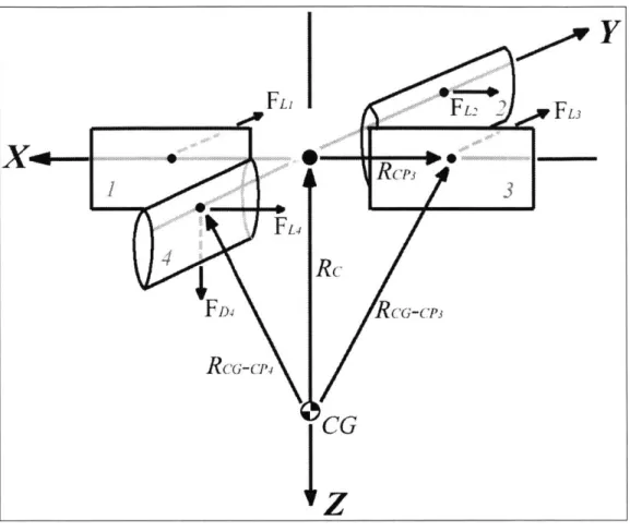
The four control surfaces of PUAV formed a cross pattern opposite the engine cylinder head. The model layout can be seen in Figure 3-6. Figure 3-7 shows a more schematic approach with the relevant moment arms and centers of gravity and pressure labeled.
RC-P3
FL4
FD4 RcCG-CP3
RCRG-Cp
CG
Figure 3-7 Schematic dynamic force diagram
As can be seen from Figure 3-7, the torque's caused by the drag forces cancel and the lift forces produce torque's proportional to the magnitude of the vector form the
vehicle Cg to the Cp of the control surface. Model Parameters
The control surfaces were modeled as symmetric NACA 0009 airfoils. Data sheetsvi indicated CD and CL values for various angles of attack and Reynolds numbers. However rotor induced velocity data indicates that the controls surfaces would see a flow velocity of approximately 35 ft/s. With a chord of one inch this translates into a Reynolds number of approximately 18,000. NACA charts plot airfoil characteristics for flows on the order
of Re 3e6. This significant discrepancy was overcome by approximating maximum lift and stall characteristics. From this an extrapolated CD lookup table was created for the NACA 0009 airfoil in a low flow regime.
Control Surface lift and drag are calculated as.
L 2
pV2
ACL Eq. 3-8D
=
pV
2ACD
Eq. 3-9The cross product of a force and the position vector from the airfoil Cp to the vehicle CG gives the total torque vector. Thus each force vector FLx is crossed with each position vector RcG-CPx. In the vehicle simulation, a vector of four control vane angles of attack is fed into a lookup table. This function finds the force of lift and drag for each of those control angles. These angles are multiplied by a direction vector according to the control surface they represent. The force of drag always acts in the Z direction, while the lift force will act in the negative X and positive Y directions alternately depending on which surface is producing the force and the angel of attack it is at.
Control Model Results
The most important finding in this analysis has been the realization that the propeller induced velocity represents a low flow regime. Thus the controls are in a primarily laminar flow, and stall at significantly lower angles of attack. Figure 3-8 and Figure 3-9 show these results for constant control deflections of 6 degrees and for a constant inflow velocity of 37 ft/s. A final important result is that the control deflections will likely not be able to produce enough torque to counter act torque produced by the rotor. Much of
this is due to the low flow conditions of the propeller induced velocity, and the relatively small size of the control surfaces which are constrained by the vehicle geometry.
3.5 Horizontal Flight Analysis
The stability of the vehicle in during horizontal flight was analyzed. In this flight mode the annular duct acts as the main lifting surface while the four internal control surfaces provide directional control. The propeller has reversed collective to the opposite direction and is acting as a pusher propeller.
* Forces Z (lb )
Six Degree Deflection
0.01 -m -A- Torques Z (ft 1b) 0.009 0.008 0.007 0.006 0.005 0.004 0.003 0.002 0.001 0 20 22 24 26 28 30 32 34 36 38 Induced Velocity (f11s)
Figure 3-8 (6) Degree control deflection
... ... ... ...
-Constant Induced Velocity (37 ft/s) 0.01 -Forces Z (1b f 0.008 F uTorques Z (ft fb) 0.006 0.004 0.002 2 4 6 8 10 1 0.002 -Control Deflection
Figure 3-9 (37) ft/s constant inflow velocity
Modeling the duct accurately was difficult without the use of a wind tunnel. In lew of those facilities data was gathered from third party analysis of ducts from other research papers". Details on the equations used for analysis were provided with the aid of co-workersVi. From acquired duct data the best L/D point was extracted as 4 at an angle of attack of 18 degrees. At this operating point the coefficient of lift was 1 and the coefficient of drag was .25. This estimates the duct as a NACA 0012 airfoil with an aspect ratio of .19
The vehicle top speed is estimated as the point where the drag of the duct is equal to the thrust. This gives the equation:
D=T=
Xpv
2SC =1ON
Eq.3-10the value of ten newtons is derived from the estimated vehicle weight of 1 Kg, and the surface area of the duct is estimated from a chord of six inches and a radius of five inches. This calculation yields a top speed of 41 m/s (80 knots).
Similarly the cruise speed of the vehicle is defined as the trim point between lift and weight. This gives the equation:
L=W
=yXpv
2SCL =1ON
Eq.3-11Therefore the vehicle cruise speed was found to be 20 m/s (40 knots).
The vehicles stall speed was calculated using the lift to drag ratio at the C1
maximum point. With a L/D of 1.8 at an angle of attack of 38 degrees the use of Eq. 3-11 results in a stall speed of 16.7 m/s (33knots). Using the vehicles estimated cruise speed in Eq. 3-10 and solving for thrust results in a value of 2.5 newtons of thrust required to cruise. The vehicles stall speed at the maximum lift condition is used in Eq. 3-10 to find the thrust required at this operating point.
To determine the characteristics of the transition maneuver a simulation was run with the canards set at an angle to produce the maximum lift from the duct. The time domain simulation was then evolved and the characteristic curve describes the vehicle's motion through transition. This simulation resulted in a transition curve with a radius of 120 feet and that would subject the vehicle to no more than 3 G's.
3.6 Summary
The use of simulation models assisted in verifying the basic design and brought us to the conclusion that the control surface layout and its interaction with the propulsion system was not entirely feasible. Both the propulsion system and the control method would need to be redesigned for more stable and robust operation. Four movable canards of 6 square inches each will be needed to maintain control authority of the vehicle through transition and in both flight modes. This size requirement would prohibit the canards from fitting within the duct. As an alternative the use of counter rotating blades was proposed. Although this would increase the complexity of the design, this configuration could produce the desired torque cancellation effects and keep vehicle size at a minimum. The concept of using the control surfaces as anti-torque stators and producing directional control by biasing them was thus deemed unlikely to work. Calculations of the vehicles aerodynamic performance did yield useful results for the basic operating parameters in flight. An annular wing of 10" diameter and 6" chord with a NACA 0012 section profile would generate enough lift to sustain forward flight at a cruise speed of 50 mph for a 3 pound vehicle. The maximum speed would be 60 mph and stall speed would be 40 mph. The transition from hover to horizontal flight would take approximately 120 feet of vertical distance and would produce forces of 3 G's on the vehicle airframe.
4 Alpha Design Cycle
The completion of initial design validity allowed for the initialization of the first of two design cycles. This alpha design phase incorporated the concept of counter rotating blades and further decreased the weight of the vehicle by decreasing the part count and increasing the use of composite materials. Modeling done in section 3.3 had pointed to a vehicle target weight of 3-4 pounds. Component layout and positioning details were finalized so that stability margins in forward flight could be estimated. Specific actuators, engines, bearings and gears were ordered. The airframe was detailed at this stage (Figure 4-1) since it would likely be an integral part of the structure supporting the drive train.
4.1 CAD Design
Ring wing duct with Battery/actuator dintegral fuel tank
EngAline Payload bay Canard wving/ control surfiace Avionics bay Dual counter-rotating reversible thrust propellers
Airframe
The airframe of the vehicle would consist of the duct, center body, and fore body. The duct would act as a rigid support for the engine and center body. The fore end of the main shaft running axially through the vehicle would secure into the fore body. This would effectively use the duct as a rigid member in the drive train. The stress loop of forces produced by the operating engine and aerodynamics would be closed along the path from the engine through the supporting spars and the duct and back into the main shaft. (Figure 4-2). Since the vehicle was relatively small in comparison to the drive train it was believed that vibration effects would be of too high a frequency to present a
problem.
ishaft / forebody
4ing
Rigid fixed
canard support
shafts
Figure 4-2 Alpha design airframe
Stress
The fore body pods would house the servo actuators used to control the four independent canards as well as the batteries used to power the radio system (Figure 4-3). The fore body itself was reserve space for a MEMS IMU developed at The Draper Laboratory for MAV navigation.
Figure 4-3 Fore body pods
Drive train
One of the most important constraints on the drive train was the need to fit it within the six linear inches of the duct chord. This meant that the stack up of drive train components (differential mechanism, variable collective and engine) must amount to no more than six inches. Iterations on stack up calculations led to the conclusion that the optimum arrangement (minimum linear spacing) would be to lay the engine on its side and run the drive train along the side of the duct and then back in to a differential drive.
Canard
Another contributing factor in this decision was that the complexity of any gears, and gear ratio changes could be built into the duct, which at 12% had a maximum thickness of 0.75" and was virtually empty. Detailed reading on counter rotating propellersix also suggested that for maximum thrust an optimum vertical spacing between the rotor disk was a ratio of 0.1 vertical spacing to rotor diameter.
The first iteration of the drive train used a rigid differential encased in a gear box mounted in the center of the vehicle. This design is shown in (Figure 4-4). However, as component weights escalated every gram of weight became critical. Much of the structure that surrounded the gearbox was unnecessary.
Drive Gear
o'-0)
0/ Counter T{Rotating Gears
Figure 4-4 Preliminary differential gearbox design
In light of weight issues and the ideal spacing of the counter rotating blades, the design was revised to that shown in (Figure 4-5). This new lightweight design used a
minimum amount of material and left the gears open. To cut down on size the propeller hubs were made essentially part of the gear. Bearings on the hubs were counter bored inside the gears to reduce vertical stack up distances. The end result was a set of counter rotating propellers with a spacing of .15 H/D.
Propeller hub/gear
Bke asrnebly
Collective
mechanism
Drive gear
Driveshaft
Gearbox mount -- 0
Figure 4-5 Revised alpha gearbox design
A primary technical issue was how to reliably transmit power from the engine outside the duct and back into the gearbox. Two competing alternatives were reviewed. The first was to use a belt drive system along the outside of the duct. The second alternative was to use two sets of beveled gears. A trade study of several miniature belt
drives showed the best belt option to be a HTD curvilinear profiled timing belt. These belts are neoprene rubber with fiber fillings and haploid curved grooves.
HTD Curvilinear Trapezoidal
Tensio Member
at Pitch Diameter .//7,/
Stress Concentrated Stress Concentrated
at Center of Tooth at Tooth Corner
Figure 4-6 HTD Belt stress concentrations
This enables the tooth load to be carried over much of the face of a pulley tooth and thus the belts are capable of higher rpm's and loads (Figure 4-6). Even with these advanced belt drives the vehicle requirements of 0.25 N/m torque at 10,000 rpm would push the belt to the limit. (Figure 4-7) A study of gear drives was undertaken.
.01 .02 .04 06.08 1 2 4 6 .8 1.0 2
Design Horespower Per Inch of
4 6 8 10
Belt Width
Figure 4-7 EPS, HTD belt selection table
~~~ ~Z~z;
__
-- - -r __ 4--1
---20,000 10,000 8,000 6.000 4.000 3,550 2,000 1,750 1,160 1,000 870 800 600 400 200 100 12 14
Computational Validation
Lewis form factor calculations were performed to determine the maximum load of individual gear teeth at the expected operating rpm and torque. The Lewis calculations are a means of computing the bending stress in gear teeth. (Figure 4-8) shows a simple cross section diagram of a gear tooth. The bending moment in this tooth is due to the tangential load Wt. With a tooth length of 1 and cross sectional dimensions F and t as
shown the bending stress can be described as:
M
Eq. 4-1
C
where
F
6
Eq. 4-2using geometry and substitution the stress con be described in terms of a gears diametrical pitch as:
Wt
P
FY
where the Lewis form factor '
2xP
3
Eq. 4-3
Eq. 4-4
Figure 4-8 Forces on miter gear mesh
The force Ft and the other forces acting on the gear were then calculated for the case of the miter gears to be used in the drive train. Figure 4-9 shows the geometry of the gears and gear forces considered. Referencei gives the forces on the gear as:
F. = F, cos a
F, =Fn
sin a
Eq. 4-5The radial force F1
Fa
Fr
can then be divided into axial and radial forces
= F, sin S
= F
1cos 15
Table 4-1 Lists the relevant geometric and dynamic information for the set of gears that was analyzed.
a
F,
F F -- --- --- 1I
Figure 4-9Directions of forces on gear mesh
Table 4-1 Lewis factor analysis case
Gear
specifi.ations
Case
Specifications
Modulus(mm) 0.5 Speed(rpm) 12000
Pitch Diameter(mm) 32 Torque(Nm) 0.19895
Pressure Angle(deg) 20 Power(watts) 250
gamma(deg)
5
Diametrical Pitch(mm)
1
tooth height(mm) 0.5 Pitch Line Velocity(m/s) 13.40373
Face Width(mm) 0.5 Kv 0.312761
Number of Teeth 32
Lewis Form Factor(Y) 0.36
The bending stresses calculated from the Lewis formula are then compared to the maximum yield stress for the gear material. In this case the stock gears are made of brass, whose yield stress is 44 (kpsi) MPA. Maximum bending stress was also be calculated as the product of several modifiers used as estimators for different physical
Pinion as Drive Gear cZ> Gear as Driven Gear
FF
FuF
properties. The equations for this semi empirical approach were supplied by the manufacturer. Reference 2 gives the stress as:
CYF = FtmY. , c
K KK
K R E q. 4-7.85 cos/Jmmb Ra-.s
KL
KFXThe resulting stress aF, was calculated with three different configurations of Eq. 4-7 resulting in values of between .29-.44 Mpa. These calculations indicated that a .8 module 20mm PD brass miter gear could withstand the forces produced during operation by a factor of approximately 100. Results are listed in Table 4-2. The module .8 gear was the smallest gear available off the shelf that had a large enough face to be bored out to accommodate the smallest bearing available off the shelf. Based on these considerations, the gear train was chosen as the best means of transmitting power.
Table 4-2 Gear force and pressure results
Ft 0.012434 Fr 0.004508 Fa 1.43E-05 bending stress(KgF/mm2) 0.298424 bending stress2(KgF/mm2) 0.06908 bending stress3(KgF/mm2) 0.441742
Variable pitch mechanism
Two factors drove the design of the variable pitch mechanism. First, the design must create a minimum blockage inside the duct, allowing as much air to flow by as possible. This constraint would drive a design that had the smallest radius about the vehicles center axis. Secondly, space within the duct was limited and must create a minimum obstruction to airflow through the duct. This constraint would drive the two
variable pitch servo actuators to one end of the duct where they could be packaged together.
With both servo actuators on one side of the propeller disks, the challenge was to create a means of actuation that could operate through or around the spinning propellers. The option of multiple links or guide wires was discussed but dismissed because of their complexity and weight. What was proposed was the concept of a non-rotating shaft on which the propeller hubs spun. If this shaft were hollow then the mechanical actuation linkage could drive through this shaft from one side of the propeller disks. Figure 4-10 and Figure 4-11 display the drive train/servo actuation mechanism.
Servo attachmren
point for variable Variable pitch pitch carner actuation rod /Ball Link Di Non-rotating / main shaft Propeller hub Gear box Threaded servo attachment point for variable pitch carrier
Variable pitch actuation rod
.7
Figure 4-11 Isometric view of variable pitch mechanism
The basic design of a variable pitch mechanism was borrowed from typical RC model designs. As can be seen in Figure 4-12 the design incorporates a brass carrier that ride on the non-rotating shaft. The interface between the brass carrier and the aluminum
shaft sees only slow linear movement when the propeller pitch is varied. The rotational motion is accommodated by two 5mm ID, 10mm OD 2mm width bearings that slip over the brass carrier. The inner race of these bearing is stationary while the outer race is bonded to the actuator arm. The actuator arm piece and the bearings are held in place by a small star retaining ring.
Threaded
Brass carrier
Actuator arm
p
Star retainers
Bearings
Figure 4-12 Exploded variable pitch actuator
carrier
)
The exact dimensions of the non-rotating shaft and the variable pitch actuating links was determined by the amount of variable pitch required. Aerodynamic models suggested that the propellers would need a maximum of ±l5' in both flight modes. To determine the linear actuation space required to create this 15' of rotation, a simple model of the mechanism was created. The variable pitch mechanism was modeled as a four bar linkage system as shown in Figure 4-13.
L
R
Figure 4-13 Four bar mechanism
The link labeled R, represents the actuating arm of the propeller blade clamp. This part is molded plastic and came off-the-shelf so its length was fixed at 15.2mm. The link labeled C represents the actuator arm that rides on the brass carrier. The length of this arm could be varied during the design phase to change the gain of the variable pitch mechanism. The link labeled L represents the link arm that would be manufactured to fit between the blade clamp and the actuator mounted on the brass carrier. The formulae governing the relationship between the three linkages, the angle of variable pitch 0, the angle of (p of link L and travel distance of the carrier x, are listed below.
x
=
LcosQp+ Rcos9
Eq. 4-8Rsin6 = Lsinyp+c
Eq. 4-9x = vL2 -(R sin6c)2 +Rcos6 Eq. 4-10
Iterations through these equations resulted in a reasonable value for the length C and a range of motion x. The resulting distance x was 10.39 mm with a linkage L of length 10mm and a linkage C of length 10mm. This allowed for a variable pitch of ±40', leaving some margin beyond the minimum requirements for variable pitch derived in aerodynamic simulation. In the design of the main shaft, adequate space was left for the carrier to traverse the length x on each side of the propeller disks.
Control Surfaces
The Alpha vehicle design incorporated four independently movable canards below the duct. In hover they would act as flight control surfaces and would aid in the transition to forward flight. Their aerodynamic shape was chosen based on calculations of the maximum output torque of the servos to be used. FMA S90 servos had the highest torque to weight ratios of all micro servos on the market (19 in/oz). Eighty percent of this torque value was taken as a maximum actuation torque and the center of rotation of the canard was found based on this.
I -/ 2 V Vm Eq.4-11
The canards would see two different flow velocities based on the vehicles flight
mode. In Forward flight the vehicle would be traveling at approximately 55 mph. Based
on simulated calculations of propeller induced velocity, the canards would see
approximately 30 mph flows in hover. The airfoil would need to be symmetric from top
to bottom because it would see flow in both directions. The center of actuation for the
canards was placed where the moment arm would not exceed 80% of the maximum servo
torque in either flight mode. The servo actuators for each canard were mounted in pods
that protrude from the duct. These pods not only house the servos, but were used to
house the batteries, and act as landing gear.
4.2 Weight and balance issues
The stability profile in both flight modes was analyzed by predicting the position of the CG and Cp in hover and horizontal flight. The CAD model of the vehicle allowed
for the prediction of the center of mass of each major weight component and its weight.
These values were entered into an spreadsheet and the CG, Cp calculations were
performed. Table 4-3 and Table 4-4 show the each individual component and its relative
weight and position to the vehicle CG. The moment arm for each element was
calculated. Early vehicle layouts gave a negative stability margin in horizontal flight.
This occurred because the engine was located at the trailing edge of the duct airfoil and
represented the largest single contributor to weight. At this stage of design all electronic
components were located in the duct and had been moved as far forward as possible.
Moving the engine to the leading edge and the propellers to the trailing edge could not
would not be sufficiently large. It was decided that the second largest contributor to weight (the batteries for the RC electronics) could be moved far forward as their profile was small and could be packaged easily. The challenge was to develop an aerodynamic means of positioning the batteries in forward of the nose of the vehicle. Concepts for this ranged from thin arching booms from the duct leading edge ending in a battery, to support rings in front of the nose and pods protruding from the duct.
Table 4-3 Structural weight distributions
Vehicle
Length =
PUAV WEIGHT BUDGET All c.g. locations relative to front nose Duct chord = 6.00 inches
Structure Duct Composite Fuselage Composite Canard Surfaces Structural Subtotal Mass grams 100.00 20.00 10.00 Weight CG1 lbs in 0.221 0.044 0.022 0.287 6.500 4.250 2.000 Ml CG2 M2 (mass) lb.-in in lb-inA2 1.433 0.187 0.044 1.665 -2.741 -0.491 1.759 1.657 0.011 0.068 1.736
