THE DESIGN AND IMPLEMENTATION OF A SERIAL INSERTION MODULE
FOR FLEXIBLE ASSEMBLY
by
Wayne R. Dempsey B.S., Mechanical Engineering Massachusetts Institute of Technology
Submitted to the Department of Mechanical Engineering in Partial Fulfillment of the Requirements for the
Degree of Master of Science
at the Massachusetts Institute of Technology
August 1995
© Massachusetts Institute of Technology, 1995
All rights reserved
Signature of Author , A I,, -. ..
Depatnent of Mechanicl Eng ering / . August 1-, 1995
Certified by
Certi fied, rofessor David Hardt Thesis Sunprir-,
Certified by ____-_,_ _
Dr. Andre Sharon
.. .. Teis Supervisor Certified by
Professor Ain A. Sonin Departmental Committee on Graduate Studies
SSACUSE-TS INSTE1UTE OF TECHNOLOGY
SEP
2 11995
kker Ew
THE DESIGN AND IMPLEMENTATION OF A SERIAL INSERTION MODULE
FOR FLEXIBLE ASSEMBLY
by
Wayne R. Dempsey
Submitted to the Department of Mechanical Engineering on August 11, 1995 in partial fulfillment of the requirements for the
Degree of Master of Science, Mechanical Engineering
Abstract
In the design of modem day products, innovation, quality of construction, and low-cost manufacturing are critical to the survival of an individual company. When a product is initially introduced into the marketplace, it is often assembled in small prototype batches and sent to potential customers for evaluation. Once market viability is proven, a vast amount of capital is invested in a high volume production line. The full implementation of these large-scale production lines often exceeds a year or more. With the pace of technology advancing rapidly, there exists a need for an intermediate solution. The primary objective of this research is to address this intermediate phase of production start-up from a flexible automation perspective. Flexible assembly systems offer moderate production output with the ability to quickly change tooling to an alternate product within a family. Within industry, a need exists to develop an automated flexible system that can quickly be used to assemble new products with little capital investment in part specific tooling, and which can than be reused to assemble other products within a family either concurrently or sequentially.
This document describes the process surrounding the detailed design and development of an automated flexible assembly system for a particular product. The goal was to design a machine that can assemble a wide range of product geometries while minimizing fixed-tooling, part-specific programming, and product changeover time. The final machine design incorporates a set of modules that are each capable of performing a specific assembly task. This document details the entire design concept as well as the design requirements involved with its development. In addition, it describes the process by which one of the modules, the Serial Insertion Module, was designed and developed into a working prototype. Concluding the document is a set of guidelines and design recommendations for developing other flexible assembly machines.
Thesis Supervisors:
Professor David Hardt, Professor of Mechanical Engineering
Acknowledgments
The author would like to thank:
Andre Sharon for being the whip that I needed to perform up to my potential. Your insight and blunt honesty gave me both the advice and guidance I needed to convince me that I can do much more than I had ever imagined.
Dave Hardt for being the ultimate professor and advisor. Your stories and discussions are insight into both engineering and everyday life are truly amazing to listen to.
Meaghan Blumberg for her love and compassion during this difficult time. Without her support, I would not have been able to complete my studies. Unfortunately, I may have paid too high a price for this thesis...
Margaret and Edward Dempsey for their support and advice throughout my scholastic career. Without the great parenting of the two of them, this would have never been possible.
Miguel Barrientos for being a calming force within the lab. The yin to my somewhat misguided yang, we made a great team. Perhaps a startup in the future...
Fred Cote for a friendly smile and a solution to every machining problem. I give many thanks to Fred for his help and assistance, as this project would have been impossible without him.
Keith Drumheller for advice on a number of topics. Thanks for your patience
and insight.
Charles and Brandon for flaming me so often, and relieving my stress on a daily basis. I will truly miss gathering you guys...
Paula Ann Dempsey for being the friend I can always count on when things go awry.
Bungie Software for both prolonging my thesis, and making it less stressful. Tiina, Moris, and Leanna for helping me out with favors details, advice, or even just a smile.
Frank Pennisi for setting such a high standard to live up to.
Walt, Diana, Dave and Joannah for being great friends exactly when
Table of Contents
A BSTRA CT ... 3 ACKNOWLEDGMENTS ... 5 TABLE OF CONTENTS ... 7 LIST OF FIGURES... 11 1. INTRODUCTION... 13 1.1 DESCRIPTION OF PRODUCTS ... . ... . ... ... 15 . /. 1I Product Terminology... ... ... ... 151. 1.2 Degree of Freedom Assembly Requirements ... ... 18
2. MISSION STATEMENT AND PROJECT SCOPE... 21
2.1 MISSION STATEMENT / CUSTOMER REQUIREMENTS ... ... 21
2. I. 1 M ission Statement... 21
2.1.2 Customer Requirements: ... .. ... ... 21
2.1.3 Assembly System Flexibility Criteria ... ... 22
2.2 ASSEMBLY TYPE COMPARISONS ... ... 23
2.2.1 Fully-Automated High-Speed Assembly ... ... 24
2.2.2 Flexible Assembly with Part-Specific Tooling ... ... 24
2.2.3 Flexible Software-Controlled Assembly... 25
2.2.4 Hand Assembly ... 25
2.3 PRODUCT ASSEMBLY OPERATIONS... ... 26
2.3. 1 Feeding and Orientation ... ... 26
2.3.2 Fixture Pickup / Clamping... 27
2.3.3 Mass Insertion of Parts ... . . .. ... ... 28
2.3.4 Serial Insertion of Parts...29
2.3.5 Part Clipping ... ... 29
2.3.6 Part Bending... ... 30
2.3.7 Product Labeling ... 30
2.3.8 Output and Inspection...30
3. OVERVIEW OF EXPERIMENTAL ANALYSIS...33
3.1 EXPERIMENTAL ANALYSIS... ... 33
3.1.2 Test Case: The MCH Product ... ... 34 3.1.3 P rocedure ... ... 35 3.2 EXPERIMENTAL OBSERVATIONS... ... ...36 3.2.1 Buckling... ... ...36 3.2.2 Insertion Forces... ... .. . ... 37 3.2.3 Gripping Problems ... 38 3.2.4 Part Damage... 38 3.3 DESIGN RECOMMENDATIONS... ... 39
4. FLEXIBLE ASSEMBLY SYSTEM DESIGN CONCEPT ... 43
4.1 SYSTEM DESIGN...43
4. I. 1 Concept Generation ... 43
4.1.2 Concept Comparison & Selection ... 44
4.1.3 System Concept Layout... . ... 44
4.2 TOTAL SYSTEM DESIGN OVERVIEW ... ... ... 46
4.3 UNIVERSAL CASING FEEDING TRAY ... ... 47
4.4 TRANSPORT M ODULE ... ... 49
4.5 MASS INSERTION MODULE...51
4.5.1 Part Indexing M echanism...53
4.5.2 Discrete Flexible Grippers... ... 54
4.6 BENDING MODULE... ... 55
4.7 UNIVERSAL CLIPPING MODULE ... 57
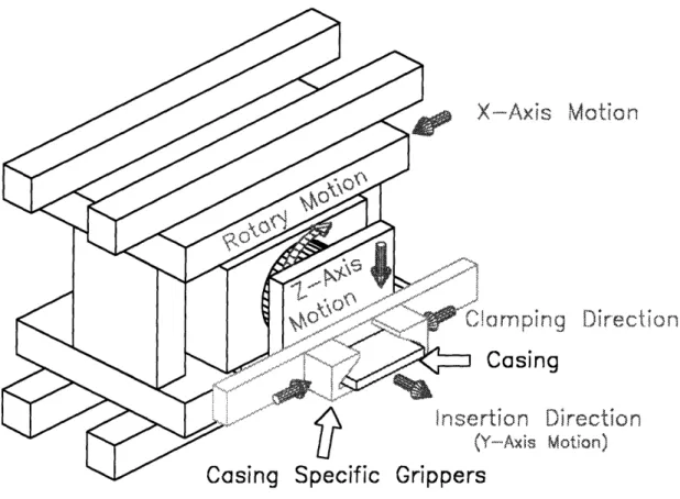
4.8 SERIAL INSERTION MODULE... ... 59
5. STAGE II DESIGN, TIMING DIAGRAM, & EXPER. ANALYSIS... 61
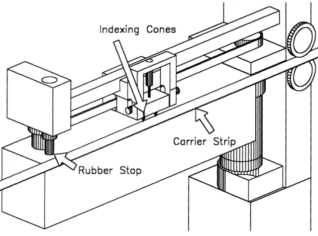
5.1 SERIAL INSERTION MODULE STAGE II DESIGN ... 6 1 5.1.1 Part Indexer Sub-Module ... ... ... 62
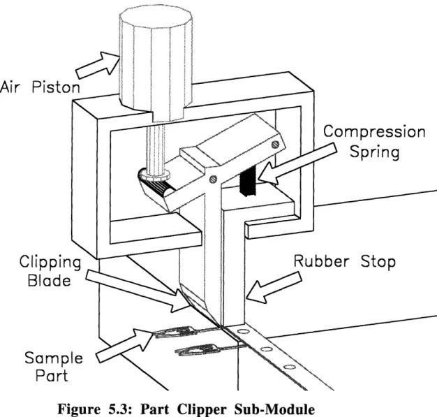
5.1.2 Part Clipper Sub-Module ... ... 64
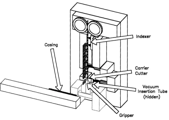
5.1.3 Rotational Part Gripper ... 66
5.1.4 Insertion V-Groove Tube ... .... . ... 68
5.2 SERIAL INSERTION OPERATIONS TIMING ANALYSIS ... ... 69
5.2.1 Solenoid Timing ... 69
5.2.2 Pneumatic Timning Experiments... . ... 70
5.2.3 Serial Insertion Module Timing Diagram...72
5.2.4 Serial Insertion Module Actuation Steps...74
5.2.5 Serial Insertion Module Timing Conclusions ... ... 75
5.3 EXPERIMENTAL INSERTION APPARATUS ... 76
5.3.2 Apparatus... ... ... 76
5.3.3 Improvement of the Experimental Apparatus ... ... 80
5.3.4 Experimental Procedure...80
5.3.5 Observations and Experimental Results... 81
5.3.6 Conclusions ... 84
6. STAGE III DESIGN: INDEXER SUB-MODULE... 87
6.1 STAGE III DESIGN INTRODUCTION... ... 87
6.2 INDEXER SUB-MODULE OVERVIEW ... ... 88
6.3 INDEXER CARRIAGE... ... 89
6.3.1 Carriage Mechanism Overview... ... 90
6.3.2 Spring Force Estimations ... 92
6.3.3 Solenoid Selection and Implementation... 94
6.3.4 Flexibility Considerations ... ... 94
6.4 INDEXER LINEAR MOTION... . ... 95
6.4. I Timing Belt Mechanism ... 95
6.4.2 Actuator Selection... ... ... 98
6.4.3 Flexibility Considerations ... ... 101
6.5 INDEXER STOPPER MECHANISM ... . . ... 102
6.5. 1 Stopper Mechanism ... ... 102
6.5.2 Solenoid Selection... 105
6.5.3 Flexibility Considerations ... 105
7. CLIPPER SUB-MODULE...107
7.1 OVERVIEW ... .. ... ... 107
7.2 CLIPPER SUB-MODULE DETAILED DESIGN... ... 107
7.3 CLIPPER CARRIAGE... ... 108 7.4 PART SHEARING... 110 7.5 ACTUATOR SELECTION... 113 7.6 FLEXIBILITY CONSIDERATIONS ... ... ... 115 8. GRIPPER SUB-MODULE...119 8.2 ROTATIONAL GRIPPER ... ... 120
8.2. I Rotational Gripper Mechanism... 120
8.2.2 Gripper Fingers Detailed Design... 123
8.2.3 Actuator Selection ... ... 126
8.2.4 Flexibility Considerations ... ... 129
8.3 GRIPPER OPENER ... .... 129
8.3.2 Actuator Selection... . ... 130
&8.3.3 Interface Requirements ... ... .. ... 130
8.3.4 Flexibility Considerations... ... 132
8.4 INSERTION MECHANISM... ... ... 133
8.4.1 Insertion Mechanism Detailed Design ... 133
8.4.2 Vacuum Pressure Part Gripper/Insertion Tube Design... 134
8.4.3 A ctuator Selection ... ... 135
8.4.4 Flexibility Concerns... ... 136
8.5 SERIAL INSERTION SUB-MODULE INTEGRATION... ... 137
9. SERIAL INSERTION PROTOTYPE ... 139
9.1 COMPUTER MODEL VERIFICATION ... ... 139
9.2 SERIAL INSERTION PROTOTYPE ... 142
9.3 SERIAL INSERTION MODULE OPERATION AND TESTING ... ... 152
9.3. I Control System Setup... 152
9.3.2 Indexer Speed Trials ... 153
9.3.3 Prototype Design Modifications ... ... 155
9.3.4 Serial Insertion Module Operation... ... 162
9.4 DESIGN RECOMMENDATIONS AND CONCLUSIONS ... ... 163
10. CONCLUSIONS...167
10.1 OVERVIEW ... 167
10.2 THE FLEXIBILITY SPECTRUM... ... 167
10.2.1 Flexibility versus Hard Tooling... 167
10.3 FLEXIBILITY WITHIN DESIGN... 168
10.3.1 Overview... .. ... ... 168
10.3.2 Reduction of Hard Tooling ... 169
10.3.3 Component Adjustability... . . ... 170
10.3.4 System Modularity ... .. . ... 171
REFERENCES ... 173
List of Figures
FIGURE 1.1: SAMPLE PRODUCT CASING ... ... ... 16
FIGURE 1.2: CARRIER STRIP VARIETIES ... ... 17
FIGURE 1.3: DEGREES OF FREEDOM REQUIRED FOR PRODUCT ASSEMBLY ... 19
FIGURE 2.1: ASSEMBLY TYPE COMPARISON CHART... ... 26
FIGURE 3.1: PART BUCKLING OBSERVED ... ... 37
FIGURE 4.1: CIRCULAR PRODUCT FLOW ... ... 45
FIGURE 4.2: LINEAR PRODUCT FLOW ... ... 46
FIGURE 4.3: FLEXIBLE ASSEMBLY SYSTEM INTEGRATED VIEW ... ... 47
FIGURE 4.4: CASING FEEDING TRAY... ... ... 48
FIGURE 4.5: CASING TRANSPORT MODULE ... ... ... 50
FIGURE 4.6: MASS INSERTION MODULE ... 52
FIGURE 4.7: PART INDEXING MECHANISM... . . ... 54
FIGURE 4.8: KNUCKLE PRESS AND DISCRETE FLEXIBLE GRIPPERS ... ... 55
FIGURE 4.9: BENDING M ODULE ... ... 56
FIGURE 4.10: UNIVERSAL CLIPPING MODULE ... ... 58
FIGURE 4.11: UNIVERSAL SERIAL INSERTION MODULE... ... 60
FIGURE 5.1: SERIAL INSERTION MODULE STAGE II DESIGN...62
FIGURE 5.2: PART INDEXER SUB-MODULE... ... ... 63
FIGURE 5.3: PART CLIPPER SUB-MODULE... ... 65
FIGURE 5.4: ROTATIONAL PART GRIPPER & INSERTION V-GROOVE TUBE...67
FIGURE 5.5: AIR PISTON ELECTRICAL TESTING DIAGRAM ... ... 71
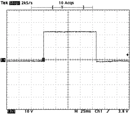
FIGURE 5.6: PNEUMATIC TIMING WAVEFORM ... 72
FIGURE 5.7: SERIAL INSERTION MODULE TIMING DIAGRAM ... 73
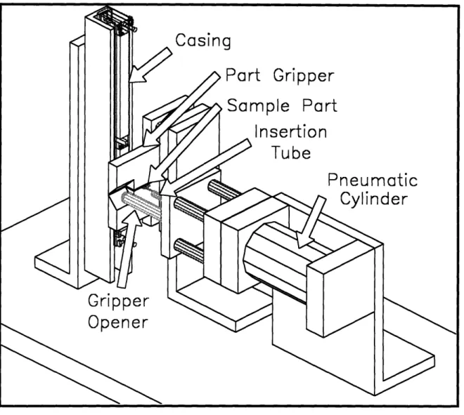
FIGURE 5.8: EXPERIMENTAL INSERTION APPARATUS... . ... 77
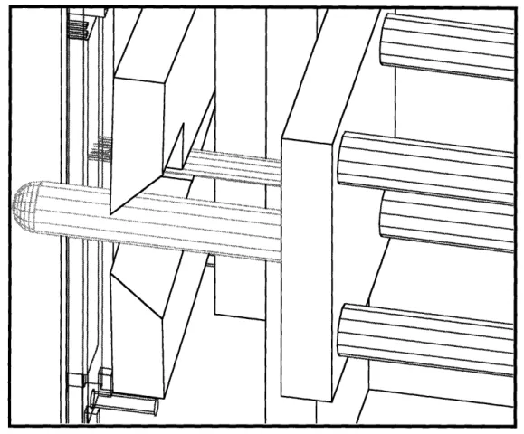
FIGURE 5.9: PART HELD IN V-GROOVE INSERTION TUBE...78
FIGURE 5.10: TOP VIEW OF EXPERIMENTAL INSERTION MECHANISM ... ... 79
FIGURE 5.11: BOTTOM VIEW OF EXPERIMENTAL INSERTION MECHANISM... 84
FIGURE 6.1: INDEXER SUB-MODULE...89
FIGURE 6.2: INDEXER CARRIAGE ... 90
FIGURE 6.3: INDEXER CARRIAGE SIDE VIEW... ... 92
FIGURE 6.4: RESULTANT FORCES ON INDEXER CONE ... ... 93
FIGURE 6.5: TIMING BELT MECHANISM ... ... 96
FIGURE 6.6: TIMING BELT MECHANISM SIDE VIEW ... ... 98
FIGURE 6.7: CALCULATED MASSES FOR INDEXER CARRIAGE... ... 100
FIGURE 6.8 VELOCITY AND ACCELERATION PROFILE ... 101
FIGURE 6.9: INDEXER STOPPER MECHANISM... ... 103
FIGURE 6.10: INDEXER STOPPER SIDE VIEW ... ... ... ... 104
FIGURE 7.1: CLIPPER SUB-MODULE ... ... ... 108
FIGURE 7.2: CLIPPER CARRIAGE AND BLADE MECHANISM ... ... 109
FIGURE 7.3: SIDE VIEW OF CLIPPER CARRIAGE ... ... 111
FIGURE 7.4: PART SHEARING ... .. ... 113
FIGURE 7.5 MOMENTS INDUCED ON CLIPPER CARRIAGE ... 114
FIGURE 7.6: LINEAR THRUSTER PNEUMATIC PISTON ... ... 116
FIGURE 8.1: GRIPPER SUB-MODULE... ... 120
FIGURE 8.2: GRIPPER SUB-MODULE WITH INSERTION MECHANISM ... ... 122
FIGURE 8.3: UNIFORM MOTION OF GRIPPERS ... ... 123
FIGURE 8.4: GRIPPER FINGERS FRONT VIEW ... ... 124
FIGURE 8.5: GRIPPER FINGER MOMENTS ... ... ... 126
FIGURE 8.6: ROTARY PNEUMATIC CYLINDER ... ... 128
FIGURE 8.7: GRIPPER SUB-MODULE WITH GRIPPER OPENER... ... 130
FIGURE 8.8: GRIPPER OPENER MECHANISM ... ... 132
FIGURE 8.9: INSERTION BLOCK AND PART GRIPPER ... ... 134
FIGURE 8.10: PART HELD IN V-GROOVE INSERTION TUBE... ... 135
FIGURE 8.11: NON-ROTATING PNEUMATIC CYLINDER... ... 136
FIGURE 8.12: SERIAL INSERTION MODULE BASE... ... .. ... 138
FIGURE 9.1: RIGHT VIEW OF SERIAL INSERTION MODULE PROTOTYPE... 140
FIGURE 9.2: LEFT VIEW OF SERIAL INSERTION MODULE PROTOTYPE... 141
FIGURE 9.3: SERIAL INSERTION MODULE PROTOTYPE... ... ... 142
FIGURE 9.4: INDEXER SUB-MODULE PROTOTYPE ... ... 143
FIGURE 9.5: SIDE-VIEW OF INDEXER SUB-MODULE... ... 144
FIGURE 9.6: CLOSE-UP OF INDEXER CARRIAGE ... ... 145
FIGURE 9.7: PARTS IN GRIPPER ... . ... 146
FIGURE 9.8: PARTS UNDER CLIPPER... 147
FIGURE 9.9: PNEUMATIC ROTATIONAL GRIPPER ... ... ... 148
FIGURE 9.10: PART PRIOR TO INSERTION ... ... .... ... 149
FIGURE 9. 11: INSERTION TUBE INSERTING PART ... . ... 150
FIGURE 9.12: SERIAL INSERTION MODULE... ... 151
FIGURE 9.13: CONTROL SYSTEM SCHEMATIC ... ... 153
FIGURE 9.14 MODIFIED CLIPPER BLADE... ... 156
FIGURE 9.15: ASYMMETRICAL HSSE PARTS ON CARRIER STRIP ... ... 157
FIGURE 9.16 MODIFIED INSERTION BLOCK ... . ... 158
FIGURE 9.17 ANTI-BACKLASH MECHANISM... ... 160
FIGURE 10.1: FLEXIBILITY SPECTRUM... ... ... 168
1. Introduction
In .the design of modern day products, innovation, quality of construction, and low-cost manufacturing are critical to the survival of an individual company. With the implementation of just-in-time inventory control, and the transportation infrastructure to support it, industrialized nations are beginning to embrace and confront a growing global economy. As labor-cost fluctuations between developing and industrialized nations are utilized, competing global companies must re-evaluate their manufacturing process efficiencies. No longer can companies survive with lackluster manufacturing capability. They must either seek out the best alternatives, or risk being eliminated from their particular market.
As often seen in new industries, the market supports many companies that are product innovators within their industry. However, as each new industry matures and price-pressures from competitors increase, the design and manufacture of these products must follow suit with increasingly efficient manufacturing processes. The time interval from which products progress from their initial design to mass-production often exceeds a year or more. During this transition stage, prototype products are assembled primarily by hand. Although effective in delivering relatively small quantities of products to potential customers, the process of hand assembly is not cost effective, and the quality of the finished product is often difficult to control. The goal of this project is to develop an automated system that can flexibly and cost-effectively assemble relatively small quantities of products during the prototypes stage.
The ongoing need to assemble products in low volume during the development and introduction of new designs is presently satisfied by the construction of manually operated machinery, which is replaced later in the product's development cycle with high speed hard automation equipment. This satisfies the immediate need of entering the market, but with high manufacturing costs and with increased product flaws due to manual labor. With the
introduction of new products, there exists a need to ramp from small volume to medium volume production, before committing a vast amount of capital resources to mass production lines. Critical to this task is the complex process of final assembly. The assembly process of certain products may involve both insertion and forming operations, and may also include the addition of other mechanical or structural elements. One of the objectives of this research is to address the start-up phase of production from a flexible automation perspective. The goal is to create a process that can assemble a wide range of product geometries while minimizing fixed-tooling, part-specific programming, and product changeover time. For this intermediate assembly stage, significant production rates are required, and the process must be capable of both economical short run production as well as medium length single product runs. Machine cost, reliability, and programming needs are additional key parameters that must be considered.
The present method of assembling these prototype products revolves around hand assembly. Small batches of hand-assembled products are delivered to potential customers for evaluation. After a product is determined to be viable in the commercial marketplace, an assembly system is designed that will be able to mass produce the products on the order of millions per year. In-between these two product development stages exists a void in the manufacturing assembly process. A flexible manufacturing system needs to be implemented that will give higher output than human assembly, yet not require the large capital investment required for the development of a full-scale high volume assembly line. In summary, the objective of this project is to develop an automated assembly system that can be quickly used to assemble a new product with little capital investment in part specific tooling, and which can than be reused for other products within a family either concurrently or sequentially.
In addition to generating a series of concepts that will solve the technical problem of flexible assembly, it is also necessary to collect relevant business data and cost information to create a realistic design tradeoff for ultimate concept selection. The concepts described in
this document include basic machine design and automation issues, flexibility, cost/complexity tradeoffs, and process programming needs. After the desired concepts are generated, various feasibility analyses need to be performed to verify the underlying principles surrounding the nature of the design.
This document describes the process by which a flexible assembly system was developed. The process of development can be described by the following series of steps:
* Determination of the Customer Requirements. * Characterization of the Assembly Process.
* Development of a Flexible Assembly System Concept. * Detailed Design and Implementation of System Components.
These steps correspond with the layout of this document, and the overall development of the flexible assembly system solution.
1.1 Description of Products
This section consists of a brief overview of some typical products that would be assembled with this flexible assembly system. The first step in designing the system involved the inspection and classification of the final product. The following section describes the necessary characteristics and processes that need to be considered in the design of the flexible manufacturing system. (See Chapter 2 for a detailed breakdown of these processes).
1.1.1 Product Terminology
The products that need to be assembled typically consist of long plastic shells or casings, and individual metallic inserts or parts. Although the casings have many unique characteristics, they share many geometric similarities which make feasible the development of a flexible assembly system. Variations in the product's geometries often include different lengths of casings and a varying number of inserts. However, there are occasions
when a particular vendor requires different material specifications for either the parts or the casing. In such a situation, a flexible assembly system would be ideal for manufacturing a relatively low quantity of products without significant startup costs and procedures. The casings are almost always injection molded plastic pieces with a distinct mating face into which the parts are inserted. Their length to width ratios are rarely less than 2:1, and they usually exhibit symmetrical properties about the plane of the mating surface. A typical casing is displayed in Figure 1.1.
Figure 1.1: Sample Product Casingi
The parts that are inserted into the casings are more diverse in nature than the casings. Their material composition is almost entirely metallic, although a wide variety of alloys and surface coatings may be used. There are three distinct types of carrier strips: side-mounted, center-mounted, and ladder-type carrier strips. The three types of strips are displayed in Figure 1.2.
Side-Mounted Carrier Strip
Center-Mounted Carrier Strip
0 0 0 0 0 0 0 0 0
0 0 0 0 0 0 0 0 0
Ladder-Type Carrier Strip
Figure 1.2: Carrier Strip Varieties
Two separate, distinct products were chosen to be the primary test beds for the flexible assembly system. These two products encompass the majority of operations required to assemble most products. The first product studied will be referred to throughout this document as the HSSE product. It consists of a long injection molded plastic body with two distinct types of metallic part inserts. The primary parts associated with the HSSE product can be inserted into the casing an entire row at a time. However,
there are secondary parts which require individual insertion operations. In addition, flash associated with the insertion of the primary part needs to be removed via a bending operation. The insertion operations involved with assembling the HSSE product are described in further detail in the remainder of this document.
The second distinct product studied will be referred to as the MCH product. It's assembly involves both the complex bending and insertion of an entire row of parts. The parts are self-staking; once they are inserted they do not move, rotate or become loose. The self-staking process requires a large amount of insertion force. Therefore, special consideration must be taken in order to assure that no buckling of the parts occur during insertion. Following the insertion process, the parts are clipped at different intervals and then bent at a ninety degree angle. Variations in the product include different length casings, and a unique surface mount product that requires special 'S' shaped bending.
1.1.2 Degree of Freedom Assembly Requirements
Through the study of many product types, it was determined that there are five primary degrees of freedom required for the assembly of the most products. These five degrees of freedom (DOF) are displayed in Figure 1.3, and consist of:
*
X-Y Plane Translation. (2 DOF) Mainly used to manipulate the part holes for insertion. May also be used to calibrate the casing position, and to regulate the number of parts used in a particular operation.* Z-Axis Translation. Primarily used in the part insertion process. May also
be used to load a casing into an assembly area.
* X-Y Plane Rotation. Necessary to flip the casings so that multiple rows of
parts may be manipulated in similar manners.
*
Z-Y Plane Rotation. Required for the bending of parts. Coupled with the X-Y-Z translation, a wide variety of bends may be produced.With these definitions in mind, Chapter 2 defines the customer requirements for the development of the flexible assembly system.
x-y
PLANE
TRANSLATIUN
z-y
x-y
PLANE
ROTATION
PLANE
ROTATION
Degrees of Freedom Required for Product Assembly
z-AXIS
TRANSLATION
2. Mission Statement and Project Scope
The design of any solution requires a set of goals and constraints that must be met to satisfy the customer. The design of a flexible manufacturing system requires that two primary conditions be met; the system must be both flexible and cost-effective. In further defining these criteria for this project, a mission statement and set of customer requirements and constraints were developed. These guidelines formed the backbone of the final design conceptualization and selection.
2.1 Mission Statement / Customer Requirements
2.1.1 Mission Statement
Based on the background provided in Chapter 1, the mission statement for the design of the flexible assembly system was formulated:
Objective: "To develop an automated assembly system that can be quickly used on a new product with little capital investment in part specific tooling, and that can be reused for other products within the family either concurrently or sequentially."
Following the determination of the mission statement, a specific set of customer design requirements were developed in order to further define the scope of the design concepts.
2.1.2 Customer Requirements:
The customer requirements for the assembly system were grouped into two distinct categories: flexibility and cost-control. The final design solution must be uniformly
balanced between these two criteria; a completely flexible solution that assembles all types of products is useless if it costs much more than simple hand assembly.
2.1.3 Assembly System Flexibility Criteria
The final flexible assembly system design must support:
* Multiple product types. Most product assemblies will be prototypes that need to be shipped in relatively small quantities to vendors. These prototypes will not have been in production before, and must be assembled quickly in quantities adequate enough to satisfy vendors.
* Easy replication for use in remote facilities. When completed, the design
system needs to be able to be implemented within various manufacturing facilities throughout the world. The design of the assembly system should include components that can be easily duplicated for use in remote facilities.
* Tolerance of manufacturing variability. The system must account for
various defects, and manufacturing errors within the parts delivered for assembly. The final design should include feedback control on the condition of the parts entering the system.
* Multiple part specifications. The maximum product size will be 7", and the
maximum number of parts per product is 500. As future development of the system continues, and products become increasingly versatile, these numbers may be subject to change.
* Multiple assembly tasks. Depending upon each individual product, parts may
need to be inserted either together in parallel or individually in series. Various post-insertion bending processes may need to be performed, as well as clipping, and labeling. (See Section 2.2)
* Rapid product change-over. The system should require a minimum
specification, the system should minimize the amount of part-specific tooling and programming required. The system should also be relatively maintenance free, and require no more than a single human operator or mechanic. Since most product assemblies will be prototypes, product changes should be easily integrated into the assembly process.
* The addition of external hardware. Additional assembly steps may be taken
to mount shells, bolts, hold-downs, etc. to products following the assembly process. The system should be flexible enough to allow for these secondary assembly procedures.
* Product marking and labeling. This is a post-assembly procedure that will
need to be performed on each product. This procedure may be coupled with the packaging/output placement of the products.
* Future product designs and criteria. The system should be precise enough
to allow for future expansion towards smaller product types. The trend of product miniaturization should be taken into account.
* Material handling. For both the components and the final product, the steady
flow of product casings and parts into the machine, and the output of finished products needs to be addressed.
2.2
Assembly Type Comparisons
When considering assembly options, there exists a wide range of options which have cost-benefit tradeoffs. As with any business decision, the benefits of an investment is weighed against its potential return. In a similar manner, with the design of multiple assembly systems, it is necessary to consider the tradeoffs between flexibility, cost, and production output. Figure 2.1 graphically displays the relationships between the different types of assembly described in the following sections.
2.2.1 Fully-Automated High-Speed Assembly
Fully-automated high speed assembly systems are designed primarily to produce a large amount of product with relatively low cost per part. The development cycle of these systems often exceeds a year. These assembly systems are built after a product has entered the initial market and proven itself viable in the commercial marketplace. The machines are
highly accurate, and are constructed specifically for the construction of a single product
type, or a single variant of a product family. Changes in the product cannot be made without significant alterations of the assembly system. The high output / low cost per part advantages justify the initial investment in the assembly system. The output of these machines often exceeds one million products per year. While very practical at high volume production, the high speed assembly system is not appropriate for the assembly of prototype products. The high initial startup costs, coupled with the initial time lag required for development, leave a void that can be filled by a flexible manufacturing system.
2.2.2 Flexible Assembly with Part-Specific Tooling
Flexible assembly with part-specific tooling is most similar to a universal machine that contains several separate tools in order to perform many tasks. Such a machine can easily assemble almost any product imaginable within a given product family, and requires significantly less programming than a completely software-controlled machine. With individual assembly stations, such a machine could conceivably assemble more than one product at a time. In addition, such a system would be significantly less complex to
manufacture and replicate on an industrial scale.
Despite these advantages, there exists the requirement to create tooling for each new product released for production. This creates a time lag, and also hinders the spread of the technology throughout manufacturing locations. Each facility must have its own set of proprietary product tooling for use with the assembly system. This increase in time and
cost suggests that the final design solution may lie in-between flexible hard tooling, and complete software-controlled assembly.
2.2.3 Flexible Software-Controlled Assembly
Flexible software-controlled assembly refers primarily to a programmable machine with no part-specific tooling involved. This type of design solution can theoretically assemble any product type within a family. The design incorporates a single working station area for quick assembly. In addition, the machine can be easily duplicated and the software copied for use in remote locations. However, the lack of hard tooling may result in lower output speed, and increased complexity in the computer programming of the digital controller. The machine will also have to be made increasingly complex in order to accommodate the wide variety of products that need to be assembled.
2.2.4 Hand Assembly
On the opposite side of the assembly spectrum is hand assembly. With only a small amount of training, a human can assemble a wide variety of products using simple hand tools or jigs. There exists no change-over time for tooling, and no software programming is involved. The disadvantages of human assembly are clear: low output speed, high operating costs, and susceptibility to human error. This is the present method of assembling prototype products; a flexible manufacturing system is needed to fill the gap between hand assembly and high-speed assembly.
Figure 2.1: Assembly Type Comparison Chart
2.3 Product Assembly Operations
After examining a wide variety of products, it was decided that the assembly process should be divided up into eight specific categories. For each product, various operations may not be necessary. A specific type of product, the HSSE, requires both parallel and serial insertion, but no bending operations. On the other hand, the assembly of the MCH product uses parallel insertion only, but requires an intricate bending process. The following is a compilation of all the assembly operations deemed necessary for the assembly of all the products examined to date.
2.3.1 Feeding and Orientation
The product casings must be fed uniformly and evenly into the assembly system. Among the various product families, there exists commonalties between product casings. The similarities that exist between product casings may be used for orientation prior to fixturing. The general length to width ratio of most casings is similar, and may be used to orient the products so that they can easily be picked up and manipulated by a fixturing mechanism.
On the surface of each product casing, there exists reference surfaces for orientation and alignment. These surfaces, primarily located on the plane of insertion, exist so that the product casings can be correctly oriented in the proper direction for forward or rear part insertion. In addition, there usually exists several plastic features which may be used to correctly determine the insertion reference surface.
The parts used in the products may be inserted into the front or the rear of the product. The orientation of the product must be determined before it is picked up by the fixturing element. In addition, the contact parts must be transported to the insertion mechanism, and removed from their own fixturing system prior to insertion.
2.3.2 Fixture Pickup / Clamping
For the flexible assembly system, a universal clamping and fixturing element is required. Since the general physical structure of all the products share a common geometric configuration, a single fixturing element can be designed that will pick up and hold the product around its edges. The major variant in grasping the product casing is the length of each product. The fixturing element must be able to clamp and hold products as small as a half an inch long, and as large as seven inches long. Assuming that the insertion forces are quite high, there needs to be concern regarding the product casing slipping within the fixture, or becoming warped from excessive applied pressure.
As an alternative to a universal fixturing element, a modular clamping mechanism can be developed. For each product, a specific holding fixture can be machined in accordance with the casing specifications. The advantages of a modular element include increased support for insertion and bending. However, machining individual fixtures for each product increases the development and tooling time, and reduces the overall flexibility of the system.
2.3.3 Mass Insertion of Parts
The mass insertion of parts refers to the insertion of an entire row of contact parts in a single motion. In determining whether mass insertion or serial insertion (see section 2.3.4) should be used, there are several factors that need to be considered. For parallel insertion, a product needs to have a significant number of parts that lie along a straight line. The number of rows on each product, coupled with the part and row pitch also determine which method is most viable.
With both methods of insertion, there is the problem of part buckling and fixturing. These problems center around the force required to insert parts into the product casing. The forces used must be less than the force required to hold the entire product, or the casing will slip and rotate out of the fixturing element. During the insertion process, the force required to insert a row of parts is equal to the force required to insert a single part, multiplied by the number of parts. Depending upon the type of product, and how the parts are inserted, this force may be either negligent, or quite significant. Some products require very little insertion force due to the secondary staking operation that secures the parts in their respective cavities. However, there exists products in which the parts are self staking,
and a significant amount of force is required to insert just one part. This force is multiplied when an entire row of parts is inserted. Thus, an actuator must be used that will apply a great amount of force quickly and accurately. The assembly system fixturing element must
also be able to hold the product casing while mass insertion is performed.
The insertion length of the parts must be carefully regulated and controlled. On some of the products there are parts that must have varying lengths. These special parts need to be inserted farther into the casing than the normal parts. In the process of mass insertion, a secondary operation will need to be performed in order to place these parts correctly. Alternatively, a special jig can be machined that will automatically space the depths of certain parts correctly. However, this option decreases the overall flexibility of the system.
Part handling is also a major concern with mass insertion. The parts are brought to the assembly system via a large wrapped wheel, similar in principle to a roll of tape. In both parallel and serial insertion, the parts must be fed into the system using a tractor-feed mechanism which unrolls the parts from the wheel. The pitch of the parts as they are brought into the system needs to be the same pitch as the insertion cavities in the product casings. The roll 'tape' of parts must be cut to specific lengths for insertion. In some types of products, there exists a center section within the casing that doesn't have parts inserted. In this particular case, a specific number of parts must be removed from the middle of the part 'tape' prior to insertion.
2.3.4 Serial Insertion of Parts
The serial insertion of parts is necessary for parts that are not located along a similar plane, or whose casing cavity pitch is different from the part roll tape pitch. Serial insertion refers to the insertion of one part at a time in series. The part handling associated with serial insertion differs from parallel insertion in that the parts often need to be rotated or moved before they are inserted into the casing. Unlike mass insertion, the forces involved with serial insertion are relatively low. Since each part is inserted individually, the parts which must protrude further into the product casing can be easily accommodated. Serial insertion holds far greater flexibility in assembly, however, this increase in flexibility comes at the sacrifice of assembly speed.
2.3.5 Part Clipping
Immediately following the insertion process, the parts are clipped to their proper lengths. The parts need to be individually fixtured during the clipping process, or they will become deformed. Because the parts need to be held tightly, a product-specific fixturing element may be necessary for the clipping process. The parts are required to be clipped prior to any bending process they may endure, otherwise clipping may distort the bend. In
most cases all the parts are clipped evenly along a single line. However, with some products, the parts are clipped to different lengths along a single line.
2.3.6 Part Bending
The process of bending the parts following insertion is the most difficult operation. With many products, the parts will need to be bent in two directions or undergo complex deformation (i.e. a curvature) that will require over-bending to achieve the final shape. Variations in the material properties of the parts may lead to inaccurate bends resulting in parts that are out of the specification limits. The required bends associated with each product vary widely. The MCH product has a complete ninety degree bend which makes it quite useful for testing design concepts and theories. Conversely, the MCR product requires complex bending maneuvers in order to achieve 'S' shaped bends that are characteristic of surface mount products. The radius of curvature of the product bends often varies with each product family. These bends require a manipulator capable of many degrees of freedom, both in linear and rotational directions. In addition, over-bending to avoid elastic deformation spring-back will need to be calculated for each product.
2.3.7 Product Labeling
The labeling of products is most likely to be one of the simpler operations in the assembly process. Laser marking systems are already in use within the mass-production systems, and can easily be adapted for use with a flexible assembly system.
2.3.8 Output and Inspection
The inspection of the products is most likely to be performed by the operator, although specific feedback controls governing the assembly process can be employed. These quality control systems will include a derivative of a computerized visual inspection
system. The finished products will be placed in containers, or a separate output feeding mechanism can be devised to stack and package the products.
3. Overview of Experimental Analysis
Following the determination of the customer requirements defined in Chapter 2, it was decided to further investigate the assembly process through an analysis and experimental investigation. On the analytical side, a finite element analysis was performed to numerically evaluate the effects of bending parts during the process of assembling the MCH product.2 The first concern of the investigation initially involved the verification of the numerical results generated by the finite element analysis study. However, during the course of this investigation, a substantial amount of knowledge was learned regarding the actual assembly process; information that could not have been gained from a simple plant tour. This information proved most useful in determining design recommendations based upon the problems and successes of the experimental study.
3.1 Experimental Analysis
The experimental analysis was performed using a multiple degree of freedom industrial robot. This device was chosen for its perceived precision, and it's seven independent degrees of freedom. At the conclusion of the experimental analysis, it was determined that this device, would alone be inappropriate for the task of flexible assembly.
3.1.1 Objectives of the Experimental Analysis
The. primary objective of the experimental analysis was to verify the results of the finite element analysis of part bending. In addition, the process of insertion and handling of parts was incorporated into the experimental procedure. The FEA analysis was based primarily upon the bending characteristics of parts undergoing plastic deformation. The purpose of the experimental analysis was to run similar experiments as those performed in the analytical study and compare the results.
2
Although the intended purpose of the experimental analysis was to confirm the FEA results, more importantly, a wide knowledge base was gained regarding the actual assembly of the products. Many problems experienced with the experimental assembly process had been overlooked in the initial design specifications, and thus formed the basis for new design recommendations. These recommendations, detailed in Section 3.3, primarily incorporate the processes of part handling, bending, and insertion.
3.1.2 Test Case: The MCH Product
The MCH product was selected to be studied both within the FEA and the experimental analysis. This particular product was chosen for its universal qualities with respect to the other product families. The bending procedure in the assembly process of the MCH is simple enough to be readily modeled using finite element analysis methods. In addition, the information learned from the study of the bending process can easily be applied to bending operations associated with other products. With the enhanced understanding of the bending process, increasingly complex variations of the MCH product could be added to the study. The MCH was also chosen for its universality with respect to insertion. The parts of the MCH may be inserted either in parallel or serial. The parallel insertion process in the MCH is perhaps the most difficult due to the self-staking nature of the parts. Once inserted, the parts do not require a secondary operation in order to constrain them. However, to avoid this secondary process, a self-staking part must be inserted into the casing using a comparatively large amount of force. This force, on the order of four pounds per part, is multiplied by the number of parts when they are inserted in parallel. Serial insertion, while requiring only a single force of four pounds per stroke, needs a much greater length of time in order to assembly an entire row of parts.
3.1.3 Procedure
The procedure used within the experimental analysis was performed using a robotic manufacturing system. The system consisted of a robotic manipulator arm with seven independent degrees of freedom. These seven degrees of freedom include the X, Y, and Z linear axes, along with a set of roll, pitch, and yaw rotational axes. In addition, the manipulator arm contained a gripper, which was able to grasp and hold various objects.
In order to securely restrain the MCH product casing, a fixture was designed and machined. In addition to fabricating a clamping fixture for the casing, a reference post and part storage station were added. The reference post was attached and used as a guide for the machine to locate, insert and bend parts. The part storage station was placed in a position so that parts could be picked up and inserted into the product casings.
The procedure for assembling the products initiated with the manipulator locating a position off of the fixture's reference post. Guiding off of the location of this reference point, the machine proceeded to the part storage area to locate and pick up the parts. Following the successful pickup of the parts, the machine then proceeded to the insertion area where the parts were rotated, positioned correctly, and inserted into the product casing. Following the insertion of the parts, a bending routine was performed which bent the parts through a rotational angle of 99 degrees. Immediately following the bending process, the gripper was brought back to an angle of 90 degrees with respect to the product casing, and the parts were released.
Despite the relatively simplistic procedure described above, the actual experiments often did not succeed in generating the desired results. Various unpredicted factors had a large impact on the output of the assembly system. These problems are described in the following section.
3.2 Experimental Observations
There were many unexpected problems which were discovered while experimenting with the pickup, insertion, and bending of the MCH parts. Some of these problems could be attributed to the many errors discovered within the robotic system. However, a fair number of problems that were discovered were originally unforeseen during the initial design requirements phase of the project. The problems observed are documented in the following sections.
3.2.1 Buckling
One of the major problems associated with the assembly of the products was part buckling. Even with successful location with respect to their mating holes in the product casing, the parts often buckled under the large amount of force required to insert them. The problem of buckling during insertion stemmed from the creation of an unstable system when the force was applied. The buckling instability problem was a major obstacle that needed to be overcome in the final design of the flexible assembly system.
Many of the observed buckling problems resulted from a distinct lack of stiffness within the manipulator arm. The manipulator was controlled using a PID control system. This system, when subjected to an error displacement, generated a resulting force related to the displacement error. In other words, when a part was inserted, it pushed back on the manipulator arm. The unstable nature of the part forced the gripper to deviate to either side of the part (motion along the X and Z axis). This motion subsequently deformed the part, and upset the delicate balance required to insert the part. The subsequent application of force caused the part to deform instead of achieving proper insertion into the product casing. The series of actions which comprise this failure mode are displayed in Figure 3.1.
SO. 90 Motion due to lack of
44
4
4
F F F F (a) (b) (c) (d)Figure 3.1: Part Buckling Observed
3.2.2 Insertion Forces
During the process of insertion, it became clear that the forces involved with parallel insertions were too high for the manipulator arm to properly actuate and drive the parts. Initially it was expected that the arm would effortlessly insert the parts into the casing using the full force of its hydraulic actuators. However, it was soon discovered that the design of the manipulator did not accommodate the high insertion forces that resulted along the axis of insertion. Initially the insertion process was attempted using five parts inserted in parallel, but the machine achieved success only about 10% of the time, when all other failure modes were eliminated. In the final testing stage, the number of parts inserted was reduced to one. This eliminated some of the buckling problems described previously, since the instability of the parts was directly related to the force applied. However, several other failure modes existed, propagating both from equipment inaccuracies and poor part/gripper interaction.
3.2.3 Gripping Problems
It was initially thought that the gripping of the parts for insertion would not pose a major problem during the process of insertion. To the contrary, part gripping evolved as a difficult issue that governed the design and characteristics of the final flexible assembly system. It was initially assumed that the parts could be held in the stock gripper fingers provided on the manipulator arm. However, after the first failed attempt at insertion, it was determined that the part insertion force was far greater than initially assumed, and that part specific gripper fingernails of some type were required. More specifically, the parts needed a type of back stop to press up against during the insertion process. This back stop provided the necessary constraint so that the parts would not slip during the insertion process.
With the addition of the part-specific gripper fingernails, it became apparent that some type of compliant rubber was needed in order to accurately constrain the parts within the gripper. A section of rubber that ran the length of the fingernails was fabricated from clear rubber stock. The rubber worked quite well, holding the parts firmly and uniformly in the grasp of the gripper.
Despite the uniform tension applied to the parts, they experienced problems with buckling underneath the rubber. It was then decided that machined v-grooves within the fingernails were necessary in order to constrain their motion, and ensure straight, even travel during the insertion process. The v-grooves worked considerably well for the insertion of the MCH parts. When all the other problems associated with the insertion process were significantly reduced, the v-grooved fingernails held the parts tightly enough to achieve success a majority of the time.
3.2.4 Part Damage
The insertion of the parts into the casing, when successful, usually resulted in some form of physical damage to the parts. During the pre-insertion phase, the handling of the parts often resulted in bent or malformed parts. In the experimental analysis, the parts
needed to be placed into the casing fixture by hand. The manual handling of parts, although generally assumed not to be performed in the final design, contaminated the surface coating of the parts. In general, the less the parts were handled, the lower the resulting damage. During the actual insertion process, the parts were often scraped within the v-grooves of the fingernails. This resulted in the removal of the vital surface coating which is necessary for the product to meet its final specifications. Precise location of the parts against the backstop is required for the elimination of this surface finish damage.
3.3 Design Recommendations
The experimental analysis provided vital insight into the necessary precision required for the insertion process. Through various calibrations, and estimates based upon human interaction within the insertion process, it was determined that positional accuracy on the order of .002" would be the minimum precision required by which the final design would achieve success. In the final design, the required precision was reduced to .001" as a standard. The location of the parts was the most important requirement for the insertion process. Precision, accuracy and stiffness needed to be combined in order to achieve the successful insertion of a row of parts.
The experimental analysis provided a realistic measure of the type of forces involved with the parallel insertion of parts into the MCH. With an average insertion force estimated at about 3 lbs, the total insertion force for an entire product would be no less than 150 lbs. In addition to supplying a support structure stiff enough to resist deflection, the force must be applied using a relatively large actuation device. This insertion force was a major factor in the overall design and implementation of the final design of the flexible assembly system. An additional concern involved the fixturing of the MCH casing during the insertion process. The casing must be held quite firmly with respect to the insertion manipulator, otherwise any stiffness inherent within the manipulator will be unessential. It was also observed that the insertion forces are so great that the actual plastic casing may
deform under the pressure imposed upon it. Specially designed backstops, engineered to reduce this deformation were implemented within the final design.
The failure mode involving buckling was instigated by a lack of stiffness within the manipulator arm. The compliance of the arm, dictated by the built-in feedback control inherent within the system, caused the arm to propagate positional errors perpendicular to the axes of the inserted parts. Following these observations, it was determined that the final design of the flexible assembly system would have to consist of a transport mechanism that resisted these forces, and was considerably stiff along the perpendicular axis. The large magnitude of forces required for parallel insertion dictated that an accompanying stiffness be inherent within the support mechanism. The instability of the part insertion procedure, detailed in Figure 3.1, requires the implementation of a stiff support structure. In addition, the transport module should contain minimal backlash. Any significant amount of backlash within the mechanism would contribute to positional errors along the axis perpendicular to the parts, and thus decrease the stability of the parts upon insertion.
The experimental analysis revealed several requirements for manipulation of the parts. It was determined through various levels of trials that the parts need to be firmly held within the gripper fingers. In the case of the experimental analysis, this involved the use of compliant rubber and v-grooved gripper fingernails. For the final design, the sideways motion of the parts needed to be constrained, and it was determined that the best solution would be to implement part specific gripper fingernails. Although decreasing the flexibility of the entire system by introducing these pieces of hard-tooling, the addition of the fingernails greatly increases the accuracy and reliability of the insertion process. In addition, it was determined that special consideration needed to be taken in order to prevent damage to the parts during handling procedures. Precise alignment of the parts within the gripper fingernails is necessary for minimal sliding along the inner section of the v-grooves. Finally, the insertion process itself requires the use of a backstop for the
alignment and placement of the parts. The normal friction force dictated by the interaction of the rubber and the fingernails proved inadequate to constrain the parts during insertion. The addition of the backstop also ensures precise depth alignment of the parts upon insertion.
4. Flexible Assembly System Design Concepti
4.1 System Design
The Flexible Assembly System design was initiated by considering two separate design options. The first option consisted of the development of a single multi-purpose machine that would be capable of performing all of the assembly operations required to produce a completed part. To a large extent, this machine design would mimic the flexible operations that a human operator is capable of accomplishing with a pair of pliers. The second option focused upon the development of a set of flexible modules, each capable of performing a specific assembly operation. These modules, acting through various coordinated motions, would be able to flexibly assemble a product from start to finish.
A comparison of the two options revealed that the modular approach was better
suited for the complex task of assembly. A modular system can be customized through the addition or removal of separate modules for the assembly of both simple and complex products. In contrast, a single multi-purpose machine would have to be designed with the most complex product in mind. Since each of the modules could be replaced independently, a modular system could be easily upgraded as improved assembly methods are developed. Finally, a modular system is increasingly robust against failure. If one of the modules were to fail, it would be easier to isolate and fix the problem. It would also be possible to quickly replace the broken module with a new one; a prohibitively expensive solution if a monolithic system were to be used.
4.1.1 Concept Generation
The selection of a modular approach to assembly led to the development of two high-level system concepts. The first system concept consisted of a relatively simple
casing handling mechanism (e.g. a conveyor belt supplied by a feeder) that can transport the casings to relatively complex insertion, bending, and clipping modules. The second system concept is a dichotomy of the first: a complex casing handling system coupled with simpler insertion, bending and clipping modules.
4.1.2 Concept Comparison & Selection
The primary selection criterion at this stage was complexity, which has a direct impact on the cost, flexibility, and robustness of the system. One way of measuring the complexity of a system is to sum the number of degrees of freedom (DOF) of all the components. A system with a simple casing handling mechanism would require that all the other modules have the degrees of freedom required to assemble the necessary parts. Since some operations share DOF requirements with others, the repetition of DOF would be unavoidable. In contrast, a system with a more complex casing transport mechanism would avoid repetition by consolidating DOF common to multiple operations. Given these considerations, the complex casing handling system concept was chosen for further development.
4.1.3 System Concept Layout
The next step in the development of the system consisted of deciding how the modules were to be laid out. Two options were considered, a circular arrangement, and a linear arrangement.
The circular rotary system, shown in Figure 4.1, clusters the modules around a rotational actuator which transports the casings. Advantages of a rotary system include the opportunity to assemble multiple casings at a time (through the use of multiple gripper arms), and the lower cost associated with rotary actuators. The primary disadvantages include lack of expansion flexibility, and the lack of precision that may be encountered
when displacing parts through small angular increments during the assembly process. An additional actuator would be required in order to allow small movements along the x-axis.
Circular Rotary System
Figure 4.1: Circular Product Flow
A linear arrangement of the modules, as shown in Figure 4.2, requires a transport mechanism that picks up casings from the feeder and transports them to the assembly modules. As products become increasingly more complex, their assembly may require additional modules to be added to the system. The use of the linear transport system along the x-axis allows for convenient expansion of the system with additional modules. One possible disadvantage of the linear arrangement is that the transport module will have to return empty to the feeding tray after each product is assembled, whereas with a circular arrangement the last module (finished product drop-off) would be next to the first module (casing feeder).