Publisher’s version / Version de l'éditeur:
Journal of Infrastructure Systems, 5, June 2, pp. 69-78, 1999-06-01
READ THESE TERMS AND CONDITIONS CAREFULLY BEFORE USING THIS WEBSITE. https://nrc-publications.canada.ca/eng/copyright
Vous avez des questions? Nous pouvons vous aider. Pour communiquer directement avec un auteur, consultez la
première page de la revue dans laquelle son article a été publié afin de trouver ses coordonnées. Si vous n’arrivez pas à les repérer, communiquez avec nous à [email protected].
Questions? Contact the NRC Publications Archive team at
[email protected]. If you wish to email the authors directly, please see the first page of the publication for their contact information.
Archives des publications du CNRC
This publication could be one of several versions: author’s original, accepted manuscript or the publisher’s version. / La version de cette publication peut être l’une des suivantes : la version prépublication de l’auteur, la version acceptée du manuscrit ou la version de l’éditeur.
For the publisher’s version, please access the DOI link below./ Pour consulter la version de l’éditeur, utilisez le lien DOI ci-dessous.
https://doi.org/10.1061/(ASCE)1076-0342(1999)5:2(69)
Access and use of this website and the material on it are subject to the Terms and Conditions set forth at Diagnostic techniques for sewer systems
Makar, J. M.
https://publications-cnrc.canada.ca/fra/droits
L’accès à ce site Web et l’utilisation de son contenu sont assujettis aux conditions présentées dans le site
LISEZ CES CONDITIONS ATTENTIVEMENT AVANT D’UTILISER CE SITE WEB.
NRC Publications Record / Notice d'Archives des publications de CNRC:
https://nrc-publications.canada.ca/eng/view/object/?id=a8a7474a-9fc8-4e2e-92c9-f439fa61c2fb https://publications-cnrc.canada.ca/fra/voir/objet/?id=a8a7474a-9fc8-4e2e-92c9-f439fa61c2fb
Makar, J. M.
A version of this paper is published in / Une version de ce document se trouve dans : Journal of Infrastructure Systems, v. 5, no. 2, June 1999, pp. 69-78
www.nrc.ca/irc/ircpubs
Diagnostic
Techniques for Sewer Systems
J.M. MakarResearch Officer
Institute for Research in Construction National Research Council Canada 1500 Montreal Road, Ottawa, Ontario
K1A 0R6 Canada
telephone: 613-993-3797, fax: 613-954-5984 e-mail: [email protected]
Abstract:
The National Research Council Canada (NRC) has recently completed a project to assist the City of Montreal in determining the condition of its water and sewer system. NRC staff members reviewed available and developing diagnostic techniques for both systems, conducted experiments on non-destructive evaluation methods and provided general scientific advice during the course of the project. This paper presents a review of current technologies for inspecting brick, concrete and vitrified clay sewer systems, including the results of three experimental investigations. The results of the review are given in a tabular form that lists the applications, advantages and disadvantages of each technique. Current and developing technologies are described that will supplement or replace closed circuit television inspection for determining the condition of sewer pipes through inspection of their internal pipe walls. In addition, techniques that allow sewer operators to investigate the pipe wall condition throughout the wall’s thickness (rather than just on the inner surface) and determine whether voids exist behind the pipe wall are described.
Keywords: non-destructive evaluation, sewer inspection, CCTV inspection, ground penetrating radar, brick sewers, concrete sewers, impact echo, natural frequency of vibration, spectral analysis of surface waves
Introduction
Most sewer systems are inspected visually by mobile closed circuit television (CCTV) systems or human inspectors (Water Research Centre, 1995). However, other techniques for inspecting sewer systems are either commercially available or are being developed. This paper discusses new and developing sewer diagnostic techniques that were investigated as part of a cooperative project between the Institute for Research in Construction (IRC) of the National Research Council Canada (NRC), the City of Montreal, Quebec’s National Institute for Scientific Research – Water (INRS-EAU) and the Centre for Engineering and Research in Urban Infrastructure (CERIU). The overall goal in the project was to determine the condition of the City of Montreal’s water and sewer systems, with IRC being responsible for advice on appropriate diagnostic techniques and acting as an overall scientific advisor.
A significant portion of the City of Montreal’s system is composed of brick and in particular 600 mm wide x 900 mm tall egg shaped brick sewers. As these pipes were amongst the oldest ones in the system (pre-1900s) and brick is known to be particularly problematic as a sewer material (Water Research Centre, 1993), the emphasis in the analysis was on techniques for inspecting brick lines. However, the same techniques are equally applicable to concrete and vitrified clay sewer systems. The results reported below were developed from a literature review, conversations with technology developers, experiments carried out by NRC staff and analysis of other sewer inspection work carried out for the City of Montreal.
Sewer Inspection Technologies
Table 1 lists the different techniques that were examined during the course of the project, including where they would be used and whether they are commercially available or still in the process of development. These techniques can be classified into three different groups. The first group, including conventional CCTV examinations, are techniques that determine the condition of the inside surface of the sewer. The second group examines the overall condition of the sewer wall and, in some cases, the soil around the pipe. Finally, the third group detects specific problems within or behind the sewer wall. Each group of techniques is discussed separately below.
Methods of inspecting the inner sewer wall surface
Examining the condition of the inner surface of the pipe wall is the standard approach to sewer inspection. Many sewer management systems use observed damage such as pipe deformations, cracking and missing bricks to determine the need for sewer repair or replacement (Water Research Centre, 1995). CCTV examination using a mobile camera system is the typical approach to this type of examination. However, there are several CCTV variants that may reduce the cost of the inspection or provide improved results. There are also alternative techniques that will work where CCTV will not or that will give direct measurements of sewer condition as opposed to the estimates produced by CCTV inspection. Wirahadikusumah and his colleagues (Wirahadikusumah, et. al., 1998) have recently reviewed some of these technologies with an emphasis on the capabilities of particular examples of automated inspection equipment. Here the general principles of
the different techniques are discussed and the results of two studies of CCTV variants given.
CCTV inspection
There are two basic types of the CCTV system. Each uses a television camera in conjunction with a video monitor, video cassette recorders and possibly other recording devices. In one case the inspection is performed using a stationary or zoom camera mounted at a manhole so that it looks into the sewer, while in the other a mobile, robotic system is placed within the sewer itself. Either form of CCTV inspection may miss certain types of defects, especially those that are hidden from the camera by obstructions as it looks down the sewer. Slight deformations of the sewer may go unnoticed, and any defects hidden beneath water inside the sewer will definitely not be found.
Stationary CCTV systems
Stationary video cameras mounted at a manhole are limited with respect to what they can see. Defects that are close to the manhole will be found, but the farther into the sewer a defect is, the harder it will be to identify and evaluate. Defects beyond the range of the camera would be missed entirely unless they cause secondary effects that can be identified at the manhole (such as changes in water flow within the pipe between two manholes). One vendor of this technology suggests that the equipment be used as part of a screening process to determine which sewer sections should be completely examined by mobile CCTV systems. Stationary CCTV’s usefulness in this respect will depend on whether the damage that can be detected by this type of system near a manhole in a sewer line is representative of that throughout the entire section of sewer line.
IRC conducted a review of CCTV tapes from seventy nine sections of the City of Montreal’s sewer system to determine where sewer damage typically occurred. Forty nine of these sections were made of brick, twenty five of vitrified clay pipes and five of concrete pipes. The brick sewers were analysed separately from the concrete and vitrified clay sewers due to the expected differences in mechanical behaviour between the pipes. These differences are due to the changing material properties of the inhomogeneous brick/mortar composite along the length of the sewer line as compared to the properties of the more homogeneous concrete or clay pipes.
The observed damage included cracking and collapses in vitrified clay pipes, pipe misalignments in the concrete pipes and mortar cracking, deformations, missing bricks, spalling and erosion in the brick sewers. The vitrified clay and concrete sewer lines had similar types of defects throughout their lengths, with each pipe in a line being cracked, deformed or misaligned. The situation with brick sewers was more complicated, with different sections of brick pipe having defects in different locations relative to the manholes at the ends of each section. The brick sewers were therefore classified into four groups: sewers with no visible damage, sewers with damage in the central region of the section, sewers with damage near the manholes, and sewers with defects in both the central region of the pipe section and near the manholes (Table 2). In this case any substantial damage within 10 metres of a manhole and any more distant damage that was large enough to be seen by a stationary CCTV system were deemed to be “near” the manhole. Damage that was both farther than 10 metres from a manhole and difficult or impossible to see by a stationary CCTV camera were considered to be “central”. Under this system of categories, sewers that only had “central” damage would be likely to be
falsely recorded by stationary CCTV inspection as having no defects at all. After being classified by category, the sewer sections were then split into groups that were longer than and shorter than a specific length in order to explore the effect of the sewer length on the results (Table 3).
Table 2 shows that approximately 24% of the brick sewers had central type defects. Further, Table 3 shows that 11 of 12 sewer sections that show only damage in the central area of the sewer have lengths between manholes of greater than 50 metres, while all of the sections had lengths greater than 40 metres. Nineteen of twenty examples where damage occurred only near the manholes had lengths of less than 40 metres. The dividing line for sewers that had damage in both regions is slightly less clear – half of these sewer sections had lengths less than 40 metres, while 10 of 14 had lengths less than 50 metres.
These results indicate that, based on structural factors alone, stationary CCTV can readily be used to inspect vitrified clay sewers. In brick sewers the most efficient use of stationary CCTV would be to restrict it to inspecting sewer lines that are shorter than 50 metres in length, although a slightly greater factor of safety in the inspections would be produced by using the technique only on pipe sections that are less than 40 metres in length. While the results suggest that concrete pipes may be inspected in the same manner as vitrified clay pipes, too few concrete pipes were examined for a definitive conclusion to be reached.
Beyond these structural factors, a decision to use stationary CCTV as a replacement or screening mechanism for mobile CCTV must be based largely on which inspection is most cost effective. In some cases the major economic advantage of
stationary CCTV is that it does not require the sewers to be cleaned so that a mobile inspection system can enter them. However, if the type of damage to be located is hidden under the debris in the sewer, cleaning will be necessary and mobile CCTV will be a preferred option compared to a stationary system.
Mobile CCTV systems
Mobile CCTV systems are the most common means of inspecting sewer lines. This type of CCTV system uses a camera mounted on a robot that enters the sewer system1. The camera generally looks forward as the robot system moves along the sewer
axis, allowing the operator to examine and evaluate the entire length between a pair of manholes. It is possible to modify this type of CCTV system to overcome many of the limitations of CCTV inspection discussed above. Some CCTV systems have “pan and tilt” cameras attached to the robot, which can find defects hidden from a forward looking camera behind connections and other obstructions within the sewer line. Sonar or ultrasound systems (see below) are often attached to robots to examine the sewer below the waterline. It is also possible to obtain CCTV equipment with a “light line” attachment to assist in quantifying smaller sewer deformations. This system projects a line of light around the circumference of the sewer being examined in order to assist in assessing the shape of the sewer.
IRC examined the performance of such a light system through an inspection of brick sewers below three streets in Montreal (Eldada, 1998). Charlevoix and Lambert-Closse streets had 900 mm x 600 mm egg shaped brick sewers, while Drummond had a 600 mm circular brick sewer. Measurements were made at 1 meter intervals along the accessible portions of each sewer. The deformation of the last sewer section had
previously been examined using a CCTV system (Seguin, 1996b), which provided a basis for comparing the accuracy of the two techniques. In each case the company providing the inspection service reported on the results of their inspection and IRC evaluated each report.
The sections examined by light line along Charlevoix show cross-sections that have heart shaped deformations. The Lambert-Closse sewer was not substantially deformed at the top of the sewer, but did show inward movement of bricks along the bottom of either side. The Drummond line showed a variety of deformations when examined with a light line system. Several sections show reductions in size around the entire diameter of the pipe. Another section shows a random distribution of deformations with both increases and decreases from the nominal pipe size at one end and large decreases at the top with corresponding increases in diameter at the other end. The very large deformations in this section suggest that the pipe is close to collapse.
The conventional CCTV inspection on the Drummond sewer line reported substantial problems (greater than 10% ovalisation, which was defined as the largest percentage deviation of the sewer from its nominal diameter) in two of the Drummond Street sections that were examined by both systems (Seguin, 1996b). Within these two sections, 14 locations with ovalisation between 5 and 10% and 9 locations with ovalisation greater than 10% were identified. It is, however, unclear from the inspectors’ report what length of sewer pipe corresponds to each measurement.
The extent of the deformations measured differs markedly between the two techniques. While conventional CCTV inspection found four separate areas of one section had deformations of greater than 10%, light line inspection found that 16 out of
18 metres of the length of the section had more than this degree of deformation, with the remaining two metres falling into the 9-12% category. In the second section, the standard inspection again found 4 separate areas that had deformations greater than 10%. Light line inspection found that 50 out of 65 metres had deformations greater than 9%, with 10 cases of deformations greater than 15%.
CCTV stills taken during the light line inspection confirm the deformation measurements made using the technique. One of these photographs is from an area that was examined by both inspection techniques. The conventional inspection does not show a large deformation in this area, but the light line photograph clearly shows a substantial deformation taking place.
The comparison of the two types of CCTV inspection suggests that a major difficulty in determining the presence of deformations in brick sewers is the lack of clear reference points. In a concrete or vitrified clay sewer deformations are accompanied by cracking, which is readily identified. In a brick sewer cracking takes place along the mortar between the bricks, which tends to hide this characteristic indication, requiring deformations to be detected by sewer shape alone. The illumination of a single cross section of the sewer by a light line system provides a reference point to improve the accuracy of sewer deformation measurements.
Computer assisted CCTV interpretation
CCTV inspections are subjective in nature (Wirahadikusumah, 1998). An inspection by two different operators may give two different ratings of a sewer’s condition, especially when the condition being recorded is difficult to precisely define.
This can present problems when a particular degree of damage is the cut-off point for whether or not the sewer line will be repaired. As an example, in some management systems (Water Research Centre, 1995), 10% or greater deformation of the sewer is considered to be a serious defect, requiring immediate action, while 5-9% deformation is considered to be less serious, requiring only regular monitoring. Due to the subjective nature of visual inspection, one inspector may consider a particular deformation to be 9%, while another would describe it as 11%. The inspection team used by the sewer owner might therefore affect the type of action taken to maintain or repair the sewer system. In addition, operator fatigue can, over the course of an inspection session, lead to mistaken judgements as to the degree of seriousness of sewer damage. While these problems can be reduced by proper training of inspectors, they can not be eliminated entirely and may therefore lead to unnecessary repairs and work not being done when it is needed.
One approach to quantifying CCTV inspections is the use of computer systems to either assist in the analysis process or to directly identify and classify defects. A recent example of this type of system uses both conventional CCTV to provide a visual record of the inspected sewer and a sideways looking optical scanning system to digitally record the condition of the sewer wall (Wirahadikusumah, 1998). This digital recording is then processed to identify cracks, pits and other damage. The inspection process is claimed to be up to four times faster than conventional CCTV, but it is currently limited to smaller diameter sewers. The major disadvantage to this type of optical scanning system is that it can not give accurate tool to pipe wall distances. As a result, the depth of damage can not be determined more accurately than could be achieved with a conventional CCTV inspection. However, an enhanced speed of inspection and the tool’s ability to make
quantitative measurements of the location and areas of defect damage mean that it can reduce or eliminate the subjectivity of conventional CCTV inspection.
Laser Based Scanning Systems
In addition to the simple light line systems described above, lasers have been used in the past to evaluate both the shapes of pipelines and the types of defects they contain (Gibert, 1997, Hibino et. al., 1994). These systems are restricted to the part of the sewer above the waterline, but they can, in theory, make possible extremely accurate inspections of sewer condition. An additional advantage to this approach is that the information from the laser scans is readily recorded and analysed by computer, substantially reducing operator errors. While the initial equipment may be more expensive than a CCTV system, the reduced operator time necessary to use the technique may also mean that its operation will be more economical. It has also been claimed to be more effective since finer defects can be detected, the results of an examination and operator fatigue, which can lead to missed defects in a CCTV examination, is reduced (Gibert, 1997).
A number of different laser based NDE tools have been developed. A Japanese system evaluates the way in which the laser light is reflected off the surface of pipes to determine both their geometry and if defects are present (Hibino, et.al., 1994). A smooth surface will reflect the maximum amount of laser light, cracked areas will reflect reduced amounts and a missing section of sewer or a crack will not reflect light at all. The system was reported to have a resolution of 0.3 mm, although that test was performed in a clean, concrete water line, rather than in a brick sewer. A small diameter (<30 cm diameter) tool is available in Germany, although the manufacturer does not specify the exact principle of operation. In Australia a semi-commercial system has been used for larger,
non-brick sewers. Laser range finders to measure both sewer shape and defect sizes are mounted on a single tool with CCTV cameras and ultrasonic transducers to give complete coverage of the sewer (Gibert, 1997). The system’s designer are currently seeking outside funding to fully commercialise the system, with one of the research goals being its adoption for use in brick sewers.
A French laser based system for inspecting sewers uses a light line system to measure pipe geometry, while a second, specialised laser head projects twin laser beams along the same axis as a video camera. The distance between the spots produced when the twin laser beams hit the walls of sewer are then used to measure the size of cracks and similar defects on the wall surface. An accuracy of 0.1 mm is quoted for measurements of overall pipe geometry and 0.3 mm for the sizing of the cracks.
Ultrasonic Inspection (Sonar)
Ultrasonic inspection is performed using a beam of very high frequency coherent sound energy, with the frequency being many orders of magnitude higher than a human being can hear (Birks and Green, 1991). The sound wave travels into the object being inspected and reflects whenever there is a change in the density of the material, with some of the energy in the wave returning to the surface and some passing on through the new material. Ultrasonic beams can be used to image the human body, inspect aircraft or examine oil pipelines. The technique is capable of detecting pits, voids and cracks, although certain crack orientations are much more difficulty to detect than others. The ultrasonic wave reflects most easily when it crosses an interface between two materials that is perpendicular to the wave. As an example, cracks that lie perpendicular to the
wave are easily detected, but cracks that lie parallel to the beam are usually not identified by an ultrasonic examination.
While ultrasound can be used to inspect concrete and similar materials, the particular geometry of sewer systems means that an inspection of the interior of the brick walls could only be performed if the ultrasonic transducers are placed directly on the sewer walls. The large difference in material properties between air or water and the pipe wall cause almost all of the sound beam that hits the wall to be reflected away from it rather than penetrating and reflecting off of defects inside the pipe wall (Birks and Green, 1991). In addition, the inhomogeneous nature of concrete and brickwork would tend to scatter and attenuate the ultrasonic energy, further reducing any signals that might be achieved.
However, this high degree of reflection means that ultrasonic beams are well suited to inspecting the inside surface of pipe walls. Typically they are used to examine the sewer below the water line and therefore complement CCTV systems which are confined to examining a sewer above the water line (Gibert, 1997, Andrews, 1998). In this case the ultrasonic wave travels through the water and then reflects off the wall, with the reflections being picked up by one or more sensors. Deformations, mortar loss and missing bricks are readily detectable with ultrasound, but the detection of cracking is more difficult, being dependent on the size of the crack and the angle it makes to the incoming beam (Birks and Green, 1991). If an ultrasonic transducer is located in the centre of a pipe, cracks in sewer walls would tend to lie perpendicular to the beam and therefore be difficult to detect. One report suggests that cracks as fine as 5 mm can be found, if very fine, slow scans are made, but that normal operation will cause such defects
to be missed (Andrews, 1998). Other potential problems for the technique include air entrainment and suspended debris in the sewer water, both of which tend to block or scatter the ultrasonic signal.
Ultrasonic inspection has also been used to examine the deformation of plastic sewer pipes and erosion and deformation in concrete pipes (Wirahadikusumah, 1998, Price, 1995). While the same ultrasonic transducers can not be used in both air and water, inspection tools have been developed that use separate transducers to allow the entire diameter of a sewer pipe to be examined. This application points out one of the major benefits of ultrasonic sewer inspection. Although ultrasonic inspection may miss cracking and other small defects, it is capable of providing a quick, quantitative assessment of sewer deformation and other problems, indicating not just the presence of the problem, but also its extent.
Discussion
Each of the techniques for inspecting the inner surface of the pipe wall provide similar types of information to the manager of a sewer system. Conventional CCTV’s long history of use means that new techniques inspecting the same area must provide substantial advantages in the quality of information provided or in lower costs before they will be adopted for common use. Table 4 summarises the advantages and disadvantages of each inspection technique.
The described modifications to conventional CCTV can assist in interpreting the results of a CCTV inspection, but are unlikely to be widely adopted unless their cost is not significantly higher than that of conventional CCTV alone. Stationary CCTV cameras are therefore the most likely application to enter common use, as they offer the
opportunity to do preliminary examinations of the shorter pipes in a city’s sewer system without cleaning. Light line systems offer noticeable advantages in identifying the presence of deformation, but are essentially an evolutionary enhancement of the standard CCTV system, rather than an revolutionary improvement.
Computer assisted CCTV examination, ultrasonic examination and laser scanning systems all offer technical improvements over conventional CCTV examination. While all three methods offer quantitative measurements of the location and extent of sewer damage, only the last two can also provide ‘depth of damage’ measurements. Laser scanning systems are capable of finer resolution than ultrasonic systems and are better at the detection of cracking, but ultrasonic inspection is a more fully commercialised technique and is readily available in North America.
Inspecting within the pipe wall and the bedding condition
Although CCTV, laser and ultrasonic systems provide images of the inside surface of a pipe wall, they do not indicate what is happening within the pipe wall or behind it. While in some cases the observed damage to a pipe is due to internal problems such as erosion, in many others the damage is caused by external forces. The following inspection techniques allow the sewer owner to examine the overall condition of an entire pipe wall, the soil behind a pipe or the pipe-soil system. Their ability to look beyond a pipe wall surface gives sewer owners opportunities to evaluate sewer condition in ways that are not possible with CCTV and similar techniques.
Wall Micro-deflections and Natural Frequency of Vibration
Measurements of wall micro-deflections and the natural frequencies of vibration of sewer lines are being developed specifically as a means of diagnosing brick sewer
condition (Eldada, 1997). The methods give information on the overall mechanical condition of the sewer line, rather than identifying specific defects.
A microdeflection in a pipe wall surface is created by applying pressure to the inside surface of the wall to very slightly deform it. In this case the intent is to measure the change in position versus the increase in pressure applied to the wall in order to indicate how well the grout between the bricks has been applied or whether the walls of a concrete or brick pipe have been damaged. It would be expected that a well grouted brick wall would expand continuously (although not equally) in all directions as the pressure increases, provided the pressure is below that which would damage the grouting. A similar, equal increase would be seen in an undamaged concrete or vitrified clay pipe. Increasing in microdeflection in one direction while decreasing in another or a sudden change in the slope of a graph of applied force versus microdeflection would suggest that the wall was damaged. The major difficulty with this technique is determining the maximum safe pressure for use on a brick wall so that the inspection method does not damage it. This pressure will depend on the pre-existing condition of the sewer. While these pressures can be readily calculated for an undamaged sewer, the accuracy of such calculations is dependent on knowledge of the strength of the mortar or concrete at any given point in the sewer. This will vary depending on the age and condition of each sewer section. Care must therefore be taken to avoid damaging sewer sections that have below normal strength but are still able to function properly. This safety consideration is not as important for concrete pipes, where the strength of the pipe material is more uniform around the pipe circumference. Microdeflections are restricted in use to rigid pipes where an entire pipe wall will be deflected by the applied force. Plastics such as
PVC and HDPE can not be inspected using this method as local deformation of the pipe wall would tend to provide a false indication of the pipe condition. The restriction of the technique to materials such as brick, concrete, metal and vitrified clay means that it is only sensitive to the wall condition, rather than that of the surrounding bedding.
Measuring the natural frequency of vibration also gives information about the mechanical behaviour of a pipe wall, but in this case the process involves vibrating the wall at a range of frequencies and determining which frequency gives the largest vibrations (the natural frequencies) (Eldada, 1997). A section of good wall would be expected to have certain characteristic natural frequencies, while deviations from those frequencies would indicate that the wall or surrounding bedding was deficient in some manner. The application of this technique depends on the development of an understanding of exactly how the natural frequencies of different types of pipe wall would be expected to change with increasing damage. However, other factors can also affect the results of the natural frequency measurement, including changes in bedding material or quality, the amount of water in the pipe and the height of ground water around the pipe. Considerable research is needed to determine if these effects can be separated from those produced by actual damage to the pipe wall.
Impact Echo/Spectral Analysis of Surface Waves
While these closely related techniques have not been reported as being used inside sewer lines, they have been successfully applied to the inspection of large, empty concrete pipes and large brick water lines. They may also therefore have applications to sewer lines. The apparatus consists of a source of controlled impacts, such as a falling weight or a large pneumatic hammer and one or more geophones that are mounted against the wall
of the pipeline. Low frequency surface waves are produced when the wall of the pipe is struck by the hammer or weight (Sack and Olson). These waves are then detected by the geophones. The major difference between the two techniques is that impact echo generally looks only at the actual waveform produced by the impact, while spectral analysis of surface waves (SASW) uses more geophones and separates the waves into different frequency components (Krstulovic, Woods, and Al Shayea, 1996). These different components travel at different speeds and penetrate to different depths in the soil beyond the pipe, allowing more information to be gathered about the condition of the pipe and surrounding soil.
Although the two techniques are similar, the use of the additional sensors and analysis in SASW means that it is possible to easily separate effects produced by soil conditions from those produced by problems in the pipe wall. SASW therefore is the most flexible of all the techniques discussed in this section since it is capable of investigating both pipe wall and soil condition at the same time. A drawback of Impact Echo and SASW inspection is that they are currently only available for manual use in large diameter tunnels that are easily accessible by human operators. Both techniques need to be automated to increase their inspection rate and allow deployment in smaller diameter pipelines. A second drawback is that cleaning of the pipe walls is likely to be required before they can be used.
Discussion
Table 4 lists the advantages and disadvantages of each of the techniques that can be used to inspect the condition of the walls and bedding of sewer lines. Both the natural frequency of vibration and the impact echo methods examine the entire pipe-soil system.
It may therefore be difficult to draw conclusions as to the cause of signal variations and determine whether they represent a problem with the pipe or a change in the bedding material. Microdeflections directly measure the mechanical integrity of the pipe wall while the analysis of SASW results can differentiate between pipe and soil effects. These two techniques are therefore more likely to be of use to the sewer manager. Neither technique is fully commercialised for use in sewer systems. Because they are not fully automated for use in smaller sewer systems, their likely use in the near term is in larger diameter sewers where past history or recent inspections of the pipe’s inner surface indicate a structural problem may exist.
Detecting conditions behind the pipe wall
Although some of the inspection techniques described previously can give information about conditions behind a pipe wall, their primary use is likely to be in determining the structural soundness of the wall itself. By contrast, ground penetrating radar may occasionally give information about delaminations in concrete sewers, but its major use in sewer lines is in detected potential problems behind the sewer walls.
Ground Penetrating Radar
Ground penetrating radar is also known by the name georadar or by the acronym GPR. Radar is well known for its ability to detect airplanes or other flying objects, but with significant adaptations it can also penetrate rocks, sand and other solid materials to detect buried objects and voids. GPR was initially developed by the U.S. Military for use in detecting tunnels and mines (Peters, Daniels and Young, 1994). It has since been employed in the mining industry (Yelf, 1990), in archeology (Goodman, 1994) and in police work (Davenport, Griffin and Lindemann, 1990). GPR is also currently in use as a
means of non-destructively evaluating the condition of highways (Clemena and Sprinkel, 1987) and concrete slabs (Bungey, 1995).
The ability of GPR to detect subsurface voids has lead to an interest in using it to evaluate the condition of sewers and other pipes. While delaminations in concrete sewers could be detected by GPR systems, much of the interest in the technique is due to its ability to examine the bedding behind the pipe wall. Voids, rocks and regions of water saturation produced by exfiltration should all be readily detectable by the technique. Recent research on this application has investigated its use in brick sewers (Price, 1995, Seguin 1996a), transport tunnels (Haack, 1995) and small diameter sewer lines (Daniels and Schmidt, 1995).
Radar systems work by emitting a coherent beam of radio waves (Peters, Daniels and Young, 1994). These waves travel through space, air or the ground until they reach an object with differing conductivity and dielectric constant, such as an airplane, a void in the ground or an area saturated with water. Part of the radar wave is reflected off the interface between the two objects and propagated back to the transmitter. The rest of the wave passes into the new object and continues to travel in the original direction. Radar beams can also be attenuated by the nature of the material through which they travel. Materials that are highly conductive, have high dielectric constants, or are magnetic will rapidly attenuate the radar beam. As a result radar is attenuated very rapidly in metals, giving essentially zero penetration, but can travel very long distances in air and space. Sand, asphalt, clay and ice fall between these two extremes, with the degree of attenuation dependant on amount of liquid water and salts present in the material. Ice is essentially transparent to GPR, allowing the technique to be used to map the bottoms of
glaciers. It can also penetrate deeply in dry sand. However, the depth of penetration in wet sand is much less, and in clays the penetration is further reduced (Benson, 1995). In these materials the presence of water increases the conductivity, while clays can also have significant dielectric constants. The presence of salt in the ground increases the soil conductivity and therefore further decreases the maximum penetration depth of a GPR system.
Experimental Work
There are two potential approaches to investigating voids near sewer systems by GPR. The first is to look at the system from the ground surface above the pipe, while the second is to examine the pipes from within the sewer line. Past work has concentrated on the second approach. During the course of the investigation of the City of Montreal’s sewer system, IRC evaluated the feasibility of using the second approach within the city. In this case the primary engineering consultant for the project wished to know if it was possible to drive a highway inspection GPR system above the City’s sewer lines and quickly find damaged areas. The results of the investigation are discussed below.
A commercial highway inspection company with ground penetrating radar expertise was contracted to perform the tests at the National Research Council Canada’s Waterline Test Facility in Ottawa. Measurements were made with 100, 200, 400 and 500 MHz commercial antennas. A representative from the antenna manufacturer assisted the inspection company in doing the tests and interpreting the data. The tests were done in the winter, so that a layer of soil next to the ground surface was frozen, reducing the attenuation of the radar beam.
Figure 1 shows the layout of the test site and the location of the voids created for this evaluation. The site consists of three 150 mm water mains (one each of PVC, cast iron and ductile iron) and two 680 mm diameter, prestressed concrete cylinder pipe (PCCP) transmission mains. The latter pipes are comparable in width to Montreal’s 900 x 600 mm sewer lines. Since this type of pipe has a steel liner, it would be expected to produce much stronger radar reflections than those from a brick sewer line. The invert of the PVC line and the PCCP lines are buried at a depth of 2.5 metres, while the inverts of the two metal mains are at 1.7 metres.
The standard void used in the test was produced by using plastic barrels with a 580 mm diameter and a 910 mm length. The first barrel was placed at location 1 in the figure next to the PVC line and was placed upright with its top at a depth of 1.42 metres. The second barrel (placed at location 2) was buried next to one of the PCCP lines with its axis parallel to that of the pipe and with the inverts of the two objects at the same depth (the top of the barrel was at 1.7 m depth). Three more voids were created away from the pipes on the site. At location three one barrel was buried with its top at a depth of 1 metre, at location 4 three barrels were buried in a pyramid shape with the top of the highest barrel at a depth of 2 metres and, finally, at location five a barrel was buried with its top at a depth of 2.5 metres. The barrels at the last three locations were all positioned with their axes parallel to the ground surface. The soil in the test site is the same type of Leda clay that is present in many areas of Montreal.
A second set of voids (Figure 2) that had been created at the end of the 1970s were also used for this test. These voids were produced by fiberglass tanks with a 2.4 m diameter and a 3.65 m height that had been partially filled with water and gravel as part of
a previous experiment on in-ground energy storage (Palmer and Svec, 1981). The tanks had been buried with their top surface at a depth of 600 mm.
Before beginning the investigation, the radar operator was informed of the number of voids to be detected and their approximate location (i.e. one somewhere along one of the metal or PCCP lines, one somewhere along the PVC line, and three between the PVC line and the road). They were also given the depths of the various water lines. They did not receive information on the exact location of the voids or their depth.
The radar operator had difficulty spotting the different pipes in the test site (Hamman, 1997). While one scan showed two pipes at approximately the right depth, other scans could not detect the pipes at all. This is particularly noteworthy as two of the buried mains were not only significantly larger than the barrels buried as voids, but, as mentioned early, of the same size and made of an easier to detect material than the bricks in Montreal’s sewers. If these pipes could not be detected consistently, there is no reason to believe that voids near a sewer would be detectable. It is likely that the clay covering the pipes at NRC’s waterline experimental site caused a rapid attenuation of the GPR signal.
The GPR system was able to locate five “voids” in the area covered by Figure 1 (locations A to E). However, not all of the located targets corresponded to real voids. In addition, the depths of those voids that were located were not measured correctly. The georadar results for voids 6 and 7 in Figure 2 show the type of strong response that might be expected from these large voids. However, the reported depths are lower than the recorded values. The objects detected by GPR are not shown in the figure since their
locations were not included in the report issued by the inspection company. It is therefore impossible to comment on how accurately they were located.
In summary, the results of the GPR test showed that:
• only two of voids 1 to 5 appear to have been correctly located;
• the depth of one of the correctly located voids was much shallower than the correct value, while no depth was reported for the second void;
• three objects (B, D, and E) were incorrectly identified as voids;
• the GPR system had considerable difficulty in locating the pipes buried at the site, including the 680 mm water mains; and
• the two older, much larger voids 6 and 7 were detected, but the GPR system overestimated their depth.
Discussion
This test showed an unacceptably high level of both false positive and false negative results. There is therefore no reason to believe that this approach to inspecting sewer lines for nearby voids would accurately detect real sewer problems at its current state of development. Moreover, both these tests were performed with the radar systems directly in contact with the ground and moved manually by a human operator. It is even less likely that a truck mounted system, operating through the air and traveling at a reasonable speed would produce useful results. GPR results are highly dependent on local soil conditions, so the usefulness of an above ground approach may vary from city to city. However, it can not be recommended at this time for use in any city with clay soils.
The alternative approach of using GPR from within the sewer system appears to be more promising. However, while past experience with GPR in other applications suggests that it should be able to detect bedding problems from within the pipe, no controlled tests on pipes with known problems have been reported. Since GPR results can be difficult to interpret, such controlled tests are necessary before this technique is commonly used as an approach to determining the condition of soil bedding behind sewer pipe walls.
Conclusions
The experimental work presented in this paper has shown that stationary CCTV systems are best used in brick sewers with lengths of less than 50 metres between manholes. Restricting those systems to use in brick sewers with less than 40 metres between manholes would provide an additional assurance that all damage within a given sewer segment would be detected. Lightline CCTV systems were found to give significant advantages in the detection of sewer deformation, but above ground GPR systems were found to be inappropriate for use in detecting voids next to sewer lines in clay soils.
These results, along with the other information presented here, were summarised in Table 4, which gave the advantages and disadvantages of each inspection technique. Table 5 lists where each inspection technique could be used and the types of results that should be expected from them, while table 6 indicates the development work that needs to be done to improve each technique and bring it to full commercialisation. It is apparent from the tables that CCTV is likely to remain the inspection method of choice in
the near future. However, laser and ultrasonic inspection methods will gradually replace conventional CCTV as the preferred method due to their ability to make quantitative measurements of sewer damage. This type of measurement will allow sewer managers to not only find where their sewers are damaged but also to track the rate of change of that damage. It is likely that inspection systems consisting of a CCTV camera, an ultrasonic transducer for examining pipes below the water line and an ultrasonic or laser system for examining pipes above the water line will become the standard approach throughout the industry. Such an approach would reduce the work load on inspectors and quantify damage while still taking advantage of current expertise on sewer failures.
More development work is required before other methods such as ground penetrating radar, microdeflections and the spectral analysis of acoustic waves come into common use as sewer inspection tools. However, these techniques offer the sewer manager the opportunity to detect pipe problems before they become visible at the inner surface and to gain a better understanding of the problems that have already been identified. Their initial application is likely to be in determining the cause and seriousness of defects identified through CCTV or similar methods. Later work may then lead to their use as independent, stand alone techniques.
Acknowledgements
This research in this report was funded by the National Research Council Canada and the City of Montreal. The assistance and information provided by staff members of Amtec Trenchless Technology, Aquadata, Hytec, NDT Engineering, Olson Engineering, Optimuss, and Silentec is gratefully acknowledged. The text is intended to describe
particular approaches to inspecting sewer lines. No endorsement of a specific company or companies is intended. The assistance of Jack Zhao in reviewing this paper is appreciated.
References
Andrews, M.E. 1998, Large diameter sewer condition assessment using combined sonar and CCTV equipment, APWA International Public Works Congress, NRCC/CPWA Seminar series “Innovations in Urban Infrastructure”, Las Vegas, Nevada, Sept 14-17, 1998, National Research Council of Canada.
Benson, A., 1995., Applications of ground penetrating radar in assessing some geological hazards, Journal of Applied Geophysics, vol. 33, no. 1-3.
Birks, A. and Green, R., 1991. Editors, Nondestructive Testing Handbook Second Edition, Volume 7: Ultrasonic testing, American Society for Nondestructive Testing, Columbus, Ohio.
Bungey, J., 1995, Testing concrete by radar, Concrete, November/December, Concrete Society, London, England.
Clemena, G. and Sprinkel, M., 1987. Use of ground penetrating radar for detecting voids under a jointed concrete pavement, Transportation Research Record, no. 1109.
Daniels, D. and Schmidt, D., 1995. The use of ground probing radar technologies for non-destructive testing of tubes, International Symposium of Nondestructive Testing in Civil Engineering (NDT-CE) pp. 429-436, German Nondestructive Testing Institute (DGZfP), Berlin, Germany.
Davenport, G., Griffin, T., and Lindemann, J, 1990. Geoscientists and law enforcement professionals work together in Colorado., Geotimes, vol. 35, no. 7.
Eldada, M. V. 1997, Auscultation des Conduites D’Egout Par Nouvelles Approches de Diagnostic, Silentec, Montreal, Quebec
Eldada, M. V. 1998, Inspection au Laser des Conduites D’egoutes des Rues Charlevoix, Drummond et Lambert-Closse, Silentec, Montreal, Quebec
Gibert, J., 1997., as quoted in Newsdesk, Insight, January 1997, pg. 9.
Goodman, D., 1994. Ground penetrating radar simulation in engineering and archaeology, Geophysics, vol. 59, no. 2.
Haack, A., 1995, Leakage, Maintenance and Rehabilitation of Transport Tunnels. Hamman, M., 1997. Utilisation du georadar pour la detection de vides au voisinage de conduites souterraines, Groupe Cartier, Montreal Quebec.
Hibino, Y., Nomura, T., Ohta, S. and Yoshida, N, 1994., Laser scanner for tunnel inspections, International Water Power and Dam Construction, June, IPC Electrical-Electronic Press, London, England.
Kuntze, H.B., et. al., KARO – A flexible robot for smart sensor based sewer inspection, Proceedings of the International Do-Dig ’95 Conference, Dresden, Germany, , pp. 367-374, 1995.
Krstulovic Opara, N., Woods, R.D., Al Shayea, N., Nondestructive testing of concrete structures using the Rayleigh wave dispersion method, Anerican Concrete Institute Materials Journal, Vol. 93, no. 1, pp. 75-86, 1996.
Lyon, J. and Mitchell, C., 1986. Ground-penetrating radar for evaluation of internal features of structures and soils., 1986 ASPRS-SCSM Fall Convention, ASPRS Technical Papers, Anchorage Alaska.
Palmer, J and Svec, O., 1981, In-ground Energy Storage - Field Test Facility, Underground Space, vol. 6.
Peters, L., Daniels, J. and Young, J., 1994. Ground Penetrating Radar as a Subsurface Environmental Sensing Tool, Proceedings of the IEEE, vol. 82, no. 12, December, pp. 1802-1822
Price, T.,1995, Inspecting Buried Plastic Pipe using a Rotating Sonic Caliper, Proceedings of the Second International Conference on Advances in Underground Pipeline Engineering, Bellevue, Washington, June 25-28, 1995, American Society of Civil Engineers, New York.
Sack, D. and Olson, L.1994, In-situ Nondestructive Testing of Buried Precast Concrete Pipe, Proceedings of the American Society of Civil Engineers 1994 Materials
Engineering Conference, San Diego, November 13-16, 1994, American Society of Civil Engineers, New York.
Seguin, L., 1996a. Auscultation de conduites d’egout par nouvelles approches de diagnostic des reseaux souterrains, Rapport #1, Geophysics GPR International, Longueuil, Quebec.
Seguin, L., 1996b. Auscultation de conduites d’egout par nouvelles approches de diagnostic des reseaux souterrains, Rapport #2, Geophysics GPR International, Longueuil, Quebec.
Water Research Centre, 1995. Manual of Sewer Classification, Third Edition, Swindon, United Kingdom.
Water Research Centre, 1993. Sewerage Rehabilitation Manual, Third Edition, Swindon, United Kingdom.
Wirahadikusumah, R., et. al., Assessment technologies for sewer system rehabilitation, Automation in Construction, vol. 7, pp. 259-270, 1998.
Yelf, R., 1990, Case histories of GPR in mining and archaeological applications, Third International Conference on Ground Penetrating Radar, Lakewood, Colorado, May 14-18. U.S. Geological Survey Open File Report 90-414, U.S. Bureau of the Interior Geological Survey, Washington, D.C.
Figures:
1. The NRC Waterline Experimental Site, showing buried pipes, buried voids (labelled 1-5) and targets identified by ground penetrating radar (labelled A-E).
Table 1 – Investigated Sewer Inspection Techniques
Inspection Technique Use Availability
Inspection of the Inner Pipe Surface
Conventional CCTV Examine pipe wall surface Commercially available Stationary CCTV Examine pipe wall surface to
select pipes for conventional CCTV examination
Commercially available
Light line CCTV Quantify deformation measurements during conventional CCTV
Commercially available
Computer Assisted CCTV Examine pipe wall surface as conventional CCTV substitute
Commercially available for small diameter pipes
Laser Scanning Examine pipe wall surface as conventional CCTV substitute
In development/Commercially available for small diameter
sewers Ultrasound Examine pipe wall surface under
water, quantify deformation measurements, Examine pipe wall
as conventional CCTV substitute
Commercially available
Inspection of Pipe Structure and Bedding Condition
Microdeflections Measure pipe wall condition In Development Natural Vibrations Measure pipe wall and bedding
condition
In Development
Impact Echo Measure pipe wall integrity, surrounding soil conditions
Commercially available for large diameter water mains Spectral Analysis of Surface
Waves
Measure pipe wall integrity, surrounding soil conditions
Commercially available for large diameter water mains
Inspection of Bedding
Ground Penetrating Radar Determine presence of voids, water, rocks near pipe exterior
Table 2 Location of Brick Sewer Defects
Location of Defect(s) seen during tape inspection
Number of Cases
None 4
Central 12
Near Manholes 20
Central and Near Manholes 14
Table 3. Grouping of damage location by pipe length
Type of Defect Number of cases in sections of less than specified length Number of cases in sections of more than specified length 40 metres None 4 0 Central 0 12 Near Manholes 19 1
Central and Near Manholes 7 7 50 metres None 4 0 Central 1 11 Near Manholes 20 0
Central and Near Manholes
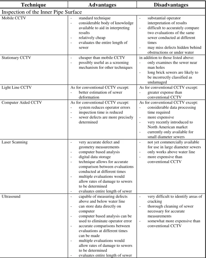
Table 4. Comparison of Inspection Methods for Brick Sewers
Technique Advantages Disadvantages
Inspection of the Inner Pipe Surface
Mobile CCTV - standard technique
- considerable body of knowledge available to aid in interpreting results
- relatively cheap
- evaluates the entire length of sewer
- substantial operator interpretation of results - difficult to accurately compare
two evaluations of the same sewer conducted at different times
- may miss defects hidden behind obstructions or under water Stationary CCTV - cheaper than mobile CCTV
- possibly useful as a screening mechanism for other techniques
in addition to those listed above: - only examines the sewer near
man holes
- long brick sewers are likely to be incorrectly classified as undamaged
Light Line CCTV As for conventional CCTV except: - better estimation of sewer
deformation
As for conventional CCTV except: - greater expense than
conventional CCTV Computer Aided CCTV As for conventional CCTV except:
- system reduces operator errors - inspection time is reduced - sewer defects are more precisely
determined
As for conventional CCTV except: - considerable data processing
time required - more expensive
- very recently introduced to North American market - currently only available for
small diameter sewers Laser Scanning - very accurate defect and
geometry measurements - computer based analysis - digital data storage
- technique allows for accurate comparison between evaluations conducted at different times - multiple evaluations would
allow rates of damage to sewers to be determined
- evaluates entire length of sewer
- not yet commercially available for use in large diameter sewers - only works above water line - more expensive than
conventional CCTV
Ultrasound - capable of measuring defects above and below water line - can store data directly on
computer
- computer based analysis can be used to eliminate operator error - accurate comparisons between
evaluations at different times can be made
- multiple evaluations would allow rates of damage to sewers to be determined
- evaluates entire length of sewer
- very difficult to identify areas of cracking
- thorough cleaning of sewer necessary for accurate measurements
- somewhat more expensive than conventional CCTV
Table 4, con.
Technique Advantages Disadvantages
Inspection of Pipe Structure and Bedding Condition
Microdeflections - not affected by bedding condition
- can be used to evaluate the entire length of the sewer line - provides a direct measure of the
pipes structural integrity - available in mobile form for
entry in 600x900 mm sewers
- rigid pipes only
- more expensive than CCTV - will not necessarily locate
individual defects
Natural vibrations - can produce an evaluation of the structural condition of the sewer - can be used to evaluate the
entire length of the sewer line - possibly able to give condition
of section of sewer without travelling its entire length - available in mobile form for
entry in 600x900 mm sewers
- effect of water inside pipe unknown
- effect of bedding condition unknown
- effect of specific defects unknown
- more expensive than CCTV - will not necessarily locate
individual defects
- may require thorough cleaning Impact Echo - can produce an evaluation of the
structural condition of the sewer - may detect voids behind sewers - known to work in brick,
concrete water lines - can be used to evaluate the
entire length of sewer
- results likely to combine pipe wall and bedding behaviours - currently only available in the
form of manually operated equipment
- more expensive than CCTV - will not necessarily locate
individual defects
- may require thorough cleaning
SASW as Impact Echo except:
- frequency analysis allows separation of response from pipe wall and bedding
- currently only available in the form of manually operated equipment
- more expensive than CCTV - will not necessarily locate
individual defects
- may require thorough cleaning
Inspection of Bedding
Ground penetrating radar from the surface
- does not require entry into the sewer
- theoretically capable of detecting voids near sewers
- highly dependent on soil conditions
- no evidence of a consistent ability to detect voids - tests have produced false
positive results - substantial operator
interpretation of results is necessary
Ground penetrating radar from inside the pipe
- detection of voids, rocks and other objects in bedding - detection of exfiltration - can detect delaminations in pipe
walls
- otherwise not influenced by sewer condition
- more expensive than CCTV - field tests required to prove
technique
- substantial operator interpretation of results is necessary
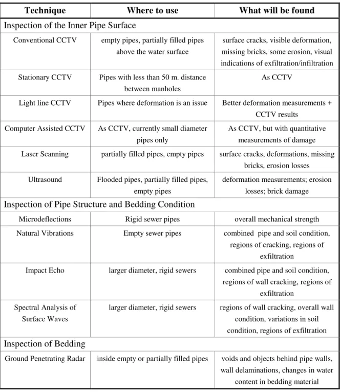
Table 5 – How to use the techniques
Technique Where to use What will be found
Inspection of the Inner Pipe Surface
Conventional CCTV empty pipes, partially filled pipes above the water surface
surface cracks, visible deformation, missing bricks, some erosion, visual indications of exfiltration/infiltration Stationary CCTV Pipes with less than 50 m. distance
between manholes
As CCTV
Light line CCTV Pipes where deformation is an issue Better deformation measurements + CCTV results
Computer Assisted CCTV As CCTV, currently small diameter pipes only
As CCTV, but with quantitative measurements of damage Laser Scanning partially filled pipes, empty pipes surface cracks, deformations, missing
bricks, erosion losses Ultrasound Flooded pipes, partially filled pipes,
empty pipes
deformation measurements; erosion losses; brick damage
Inspection of Pipe Structure and Bedding Condition
Microdeflections Rigid sewer pipes overall mechanical strength Natural Vibrations Empty sewer pipes combined pipe and soil condition,
regions of cracking, regions of exfiltration
Impact Echo larger diameter, rigid sewers combined pipe and soil condition, regions of wall cracking, regions of
exfiltration Spectral Analysis of
Surface Waves
larger diameter, rigid sewers regions of wall cracking, overall wall condition, variations in soil condition, regions of exfiltration
Inspection of Bedding
Ground Penetrating Radar inside empty or partially filled pipes voids and objects behind pipe walls, wall delaminations, changes in water
Table 6 – Needed Developmental Work
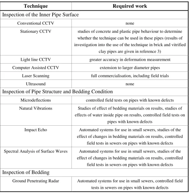
Technique Required work
Inspection of the Inner Pipe Surface
Conventional CCTV none
Stationary CCTV studies of concrete and plastic pipe behaviour to determine whether the technique can be used in these pipes (results of investigation into the use of the technique in brick and vitrified
clay pipes are given in reference 3) Light line CCTV greater accuracy in deformation measurement Computer Assisted CCTV extension to larger diameter pipes
Laser Scanning full commercialisation, including field trials
Ultrasound none
Inspection of Pipe Structure and Bedding Condition
Microdeflections controlled field tests on pipes with known defects Natural Vibrations Studies of effect of bedding materials on results, studies of
effects of water inside pipe on results, controlled field tests on pipes with known defects
Impact Echo Automated systems for use in small sewers, studies of the effect of changes in bedding materials on results, controlled
field tests in sewers on pipes with known defects Spectral Analysis of Surface Waves Automated systems for use in small sewers, studies of the
effect of changes in bedding materials on results, controlled field tests in sewers on pipes with known defects
Inspection of Bedding
Ground Penetrating Radar Automated systems for use in small sewers, controlled field tests in sewers on pipes with known defects