CASE STUDY IN RAPID PRODUCT DESIGN AND DEVELOPMENT
byGarrett L. Winther
Submitted to the Department of Mechanical Engineering in partial fulfillment of the requirements for the Degree of
Bachelor of Science at the
Massachusetts Institute of Technology June 2011
@ 2011 Garrett Winther
All Rights Reserved
ARCHIVES
MASSACHUSETTS INSTITUTEOF TECHNOLOGY
OCT
202011
LIBRARIES
The author hereby grants to MIT permission to reproduce and to distribute publicly paper and electronic copies of this thesis document in whole or in part in any medium now known
or hereafter created.
Signature of Author
Certified by
Department of Mechanical Engineering May 16, 2011
aria C. Yang
Assistant Professor of Mechanical Engineering and Engineering Systems
Accepted by
John H. Lienhard V. Mechanical Engineering Undergraduate Officer
CASE STUDY IN RAPID PRODUCT DESIGN AND DEVELOPMENT
byGarrett L. Winther
Submitted to the Department of Mechanical Engineering on May 16, 2011 in partial fulfillment of the requirements for the Degree of Bachelor of Science in Mechanical
Engineering
ABSTRACT
This thesis explores a new strategy in developing products quickly, cheaply and efficiently, with the hopes to redefine the paradigms behind the product design process. This was carried out through the development of the product "flatRat", a commemorative MIT novelty ring. With this product, we explored different prototyping techniques, manufacturing processes, and business strategies with the hope to optimize the process for others to carry out similar projects. This thesis summarizes a selection of work from the development of flatRat from concept generation to final product sales.
The ultimate goal of this project was to bring a product to life with limited resources. From the project's beginning in June, 2009 to its capstone in February, 2011, flatRat was designed and developed fully into a marketable product followed by an initial manufacturing run of 500 units. These were sold to MIT's Class of 2013 Ring Committee and given away to attendants of the "Ring Premiere" Ceremony on February 11, 2011. This product is currently being developed further to be sold at the MIT Museum and Campus Bookstore. The process developed around this product is currently being implemented at Olin College of Engineering under Dr. Lawrence Neeley.
Thesis Supervisor: Maria Yang
TABLE OF CONTENTS
ACKNOW LEDG EM ENTS ... 3
INTRODUCTION ... 5
1 CO NCEPT G ENERATION ... 6
1.1 BENCHM A RKING... 8
1.2 BRA INSTO RM ING ... 10
2 CO NCEPT SELECTIO N... 16
2.1 The "flatRat"...16
3 PRO TOTY PING ... 18
3.1 VISUA L PROTOTYPING ... 18
3.2 PA PER PROTOTYPING... 19
3.3LA SER CU l ING ... 34
3.3.1 LASER PROTOTYPING ... 38
4 CHEM ICA L ETCHING ... 46
4.1 DESIGNING FOr CHEMICAL ETCHING ... 46
4.2 CHEMICAL ETCHING PROTOTYPING... 50
4 FINA L PRO DUCT ... 58
5 D ISCUSSIO N ... 63
REFERENCES ... 66
ACKNOWLEDGEMENTS
First and foremost, I would like to acknowledge the influence of my two project advisors Prof. Maria Yang and Dr. Lawrence Neeley. They were both invaluable resources to both the thesis project and my development as a designer and engineer. Their continued involvement and excitement has been the backbone of this project and I will always be grateful for their help.
I would also like to acknowledge the work of Paul Uche '13 who assisted with a
almost every aspect of the final production of flatRat. His involvement was a tremendous help and made the thesis a true success.
Lastly, I would like to thank MIT's Department of Mechanical Engineering who funded this project for the past two years along with providing the facilities to make it possible.
Introduction
There are a multitude of product development strategies being implemented throughout industry, all with the hopes of bringing profitable ideas to market. An idea usually needs a considerable amount of money, time and man power to fully develop itself from a promising concept to a profitable item. There are exceptions to these standards, but most products on store shelves are backed by large amounts of money with vast resources for prototyping, marketing and distribution. This leaves a significant barrier to entry into the product market to those who cannot overcome the standard cost associated with product development and distribution.
The goal of this project is to develop new avenues that a product can come to life ,
focusing to minimize time and resources in its development. By doing so, we hope to make the product development process more accessible and allow more ideas to come to market from a variety of backgrounds. We are exploring these strategies via several products that allow us to test our new processes first hand while assessing and optimizing their potential for widespread use. The flagship product of this research project is the "flatRat", a foldable MIT class ring, also know as the "Brass Rat". Over the past two years, we have explored a multitude of tools under this concept and it has developed into a complete product we are
currently producing and selling. This paper will outline the development of the "flatRat" and
highlight our exploration into prototyping, manufacturing, and distribution strategies that will in turn, apply back to a process that makes product development accessible to a wider range of people.
It should be made clear that the goal of this project is not to redefine design process in large companies or for designers that have the knowledge to adequate produce their products, but rather develop new strategies to make product development available to a new audience. There is currently a large population of inexperienced designers that will benefit from a renovated and consolidated design process, which we hope to deliver.
I
Concept Generation
The first part of any product development process is generating a concept. This time is incredibly crucial to the rest of the process and ultimately leads to the success of a product. Most products are derived to fill a user need or fill a user need better than an existing solution. Our products ultimately look to do the same, but the foundation of the process is changed due to the constraints and goals of the project.
Rather than generating concepts specifically around user needs, we focused our idea generation around low cost manufacturing processes. This allows us to control the rest of the process for any idea as long as it fits first within this first manufacturing constraint. If we left it unconstrained, ideas would potentially arise that were out of the scope of our process and require complex manufacturing or assembly. For example, if an idea required complex
3D surfaces it would potentially call for injection molding or some other similar manufacturing process. Though these aren't completely out of reach, they come with a set of potential issues and details that would be overly complex for the initial stages of our project and may be out of scope for the first iteration of our process. That being said, we decided to begin with simple, 2 dimensional manufacturing processes and set boundaries for ideas to only be manufactured in that space.
The decision to limit to specific manufacturing processes gives a good set of boundaries for what a product might be within our process, but doesn't create too great of limits such that new and interesting ideas cannot come out of it. The most important aspect of this decision is that we can control the more detailed steps later in the process, such as prototyping and design for manufacturing. We can then provide adequate instruction and guidance through these controlled steps and avoid the variances that may cause delays and cost money. This also puts the project within scope for our team, allowing us to control one variable at a time instead of worrying about breadth of potential options that we haven't completely explored. By mastering the in's and outs within our initial constraints, we will have a robust process that can handle a wide range of potential products. We can then move to on to control subsequent steps that will then expand the capabilities of our process. After we have complete control over the complete set of skills for one specific manufacturing
process, we can then begin to explore another and master the process involved in that form of production.
Ultimately, we aspire to control a wide range of manufacturing processes such that idea generation will no longer be constrained by production. This would allow a designer to completely focus on a user need and then find the prototyping, manufacturing and distribution path to take their idea through full development, no matter the variety or complexity of each step that may be necessary. This end goal will take a considerable amount of work and time, but by steadily working and mastering each step, a full catalog of potential options will be developed and open to users.
This thesis explores the first of these options with products that are (1) purely mechanical and (2) manufactured by 2 dimensional processes. This means that the form of a product or each piece within a product is determined only by variations in the X-Y plane with a controlled Z. The material will have a set thickness and the manufacturing process will be able to alter the area and shape of the flat plane but it cannot vary the thickness or depth a part. This would be like having a piece of paper that you cut to any shape you want, but you can't make the piece of paper thicker at any point. You may be able fold it or bend it to change the shape but the initial thickness cannot be altered.
This control over the first products is critical for controlling a lot of the primary steps of the development process. Two dimensional products have some pros that allow us to control a lot of the process and also easily transfer it to a wider population. First, the manufacturing processes are relatively intuitive and the tools for designing are all easily accessible. The packaging for these products is also straightforward. With two dimensional products, one only needs 2D packaging which can be as simple and cheap as an envelope. This in turn leads to easy shipping and distribution, with smaller objects being as easy as standard USPS first class mail. These are all in line with our initial goals of limiting time and
cost associated with our process along with simplifying our first run.
The constraints take products down to a very simple level and will not only allow us to optimize the steps of the process but we will also optimize how we learn and document these processes for others. The key to the first stage of this project is learning how to assemble information and details about every aspect that may arise in each process. Initially
we planned on this to be a quick and non-trivial aspect but this first run took much longer than expected. Even though we constrained the project to these low level products, we had to learn how to learn from our work and how to translate it into a meaningful process. This was an incredibly important part of the project allowing us to refine how we approached subsequent steps and how the interact. We were also able to encounter most of the problems that arise in these manufacturing or prototyping processes which may help future designers avoid pitfalls in their projects.
1.1. Benchmarking
With these constraints in place, we began our first iteration of our development process in June of 2009. Our first step was to introduce ourselves to the space we were working in by benchmarking current products that used similar manufacturing processes as the ones we were limiting ourselves to. Benchmarking is the observation of current standards among products that currently exist and how they are implemented into the
market. This step allows us to get a good idea of what is currently being sold, how far the technology can take us, and what has actually been successful in the market. By collecting all this information, we can further guide our concept generation and optimize our decision
based on the details of existing products.
At this point in the project, we had inclination towards laser cutting as a manufacturing process due to our easy access to the machines and its capabilities to prototype within our constraints. As we continued our research in the following months, we expanded the breadth of our scope to other manufacturing but the initial benchmarking efforts were constrained to simple 2D products that had the potential to be laser cut. All products were recorded by name, brief description, and commented on as shown in the spreadsheet in Appendix A on the following page.
As we went through this step in the process, it actually proved to be potentially useful in cutting time off the overall process, which was one of our primary goals. In our case, we we're able to learn a tremendous amount from simply exploring the current market and how the technologies are used. For example, Flgure 1 demonstrates abstract geometries and
interactions that can be used with the the laser cutter. We could have explored and eventually come to the conclusion that we could make a product such as the elephant skeleton, but it would take a lot of time to get there. By evaluating the market, we saw the products that are using the technology fully and the potential for our product.
Figure 1 :Laser cut elephant skeleton held together without adhesive. Epilog Laser Company [1]
The benchmarking process also included a basic search for user needs and how some of the products that we observed were filling those needs. There was a particular focus to wallet sized items that were the size of a credit card but also served a particular function. These ranged from complex multi-tools to bottle openers to purely aesthetic novelties, all of which were flat packed to fit in a compact space shown in Figure XX.
I
Another interesting theme of products take 2D pieces and manipulate the final form to become a 3 dimensional product, both functionally and aesthetically. These products were particularly appealing because they offered new potential for our product to take more advanced shapes and functions beyond some of the simpler flat packed objects we observed. Some of the benchmarked products in Figure XXX show the potential for a flat
product to be altered into 3 dimensional form.
Figure 3 :Mikro Man figure "Off Road". Begins flat and folds up to figure on bike [5]
The Mikro Man product line, as shown in Figure 3, have based their entire company around this technique. Their initially single flat piece bends into an artistic toy figure.
1.2 Brainstorming
The primary goal of the previous steps is to create a certain level of controlled idea generation within the brainstorming process. By ensuring all the constraints are known and understood, the time spent brainstorming can be incredibly effective in finding a good idea that fits within our specific process. Brainstorming, in product design, is the formal process of generating new ideas. Good ideas don't always come in a single of moment of inspiration, but most often come during an organized brainstorming session that has been set up with a specific set of goals and constraints. These sessions help generate a multitude of ideas that afterward can be filtered to good and bad ideas, and during the evaluation the best ideas
can be down selected to the best solution. This section will review the overall function and strategies of brainstorming while also outlining the results of our own brainstorming session.
The following section is an example of how we might translate this process to people who are new to brainstorming along with giving a basic outline of how our process works in
relation to this paper.
Guide To Brainstorming
First and foremost, the main purpose of a brainstorming session is to come up with as many ideas as possible. You may think that your only goal is to come up with one good idea that you can turn into a product, but that isn't the case for brainstorming. Brainstorming
allows you to come up with a multitude of ideas that, until the end, should be considered of equal value to your project. Never evaluate your ideas while your brainstorming, just worry about getting lots ideas out. The more ideas you generate, the better chance you'll find a good one along the way and the more options you have when you want to make your final
decision.[6]
A brainstorm session is structured in order to promote a multitude of ideas. There are
developed rules and guidelines that professionals to amateurs alike use to have the most efficient brainstorming sessions. Most often, a group of people will get together in a quiet and comfortable area to have a brainstorming session. There are established rules beforehand and a set an amount of time to generate ideas. The brainstorm begins with a prompt, and everyone then proceeds to think of ideas, document them, and present them to the group. It is meant to be a fast paced process with ideas flying for however long you have
set to brainstorm. To get good results, we have created a checklist for the optimal brainstorm.
Checklist for Brainstorming Setup
- People - You can brainstorm all by yourself, but studies have shown that the best
also enough brainpower to put out a lot of ideas. They don't have to be people part of your project and sometimes its better to bring in different people to get new perspectives and hopefully new interesting ideas.
- Place - Find a place that everyone can be comfortable and can easily communicate with
one another. A wall, dry erase or chalk board are a plus.
- Tools - One of the most critical parts of the set up is developing a universal mode of
documentation. Everyone needs to document their ideas the same way and you need to have a way to have all the ideas presentable to the rest of the group. Here are two ways that you may want to do it:
- Paper and Pin Up - Everyone should have a stack of paper and a marker. As you come up with an idea: draw a quick sketch, put a descriptive name on it, give a quick description to everyone in the group, and pin it up so that everyone in the group can see it. It is important that you announce and pin your ideas visibly. First, so that they don't waste their time writing down the same idea if they think of it later
in the brainstorm and also that they can potentially build off it into other ideas.
- Dry Erase/Chalk Board and Recorder - In this scenario, one person is designated as the idea recorder. Everyone comes up with ideas, gives a quick description and the recorder writes down a descriptive word or picture to record the idea on the board.
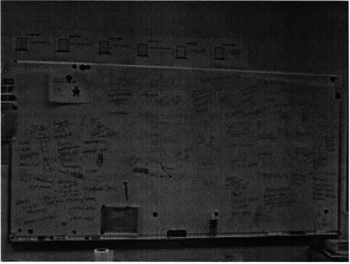
Figure 5 :Dry Erase brainstorm session for flatRat project held June 2009 Rules To Brainstorming
- Establish a set of rules for the session and make sure everyone knows them. This is
important to how well your brainstorm flows and the quality and quantity of your ideas. Here is a basic set of rules that should lead to a productive brainstorm:
1. Focus on Quantity - As mentioned previously, brainstorming is all about getting lots of
ideas out there. Encourage people to put out every idea that pops into their head.
2. Withhold Criticism - There are no good or bad ideas during a brainstorm, just ideas. Don't waste critical thinking time on evaluating the intricacies of any idea.
3. Welcome Unusual Ideas - Thinking out of the box is key to potentially finding a new and
innovative idea. Even if something isn't feasible, there may be aspects of it that will contribute to other people's ideas and lead to something interesting.
4. Combine and Improve Ideas - There is no idea ownership during a brainstorm, therefore you can take someone's idea and build on it or change it to a new and interesting idea
5. Have Fun - This shouldn't be a frustrating process but should be an enjoyable time to
thinking creatively and put out a ton of ideas.
- Set a time limit -You should limit your brainstorms to between 15 and 30 minutes. This amount of time is long enough that people can think through things thoroughly but not exhaust people creatively. It also yields a manageable quantity of ideas that you can evaluate later.
- Prompt - You should have a designated prompt to focus what you are brainstorming for. In
this case you'll be looking for "2D or 2D->3D products". You want it to be directed but not too open ended such that your ideas are all over the place.
- GO! - Even if you don't have any experience, give it a shot and see how many ideas you can
put out.
We set up a brainstorm session to think about potential 2D products made by laser cutter. Everyone who was involved was prepared by looking over the benchmarked products and contributing products to the list that they found. Everyone was given the rules of the brainstorm and the prompt for 2 dimensional products leading to a multitude of ideas as seen in the Figure 5 above.
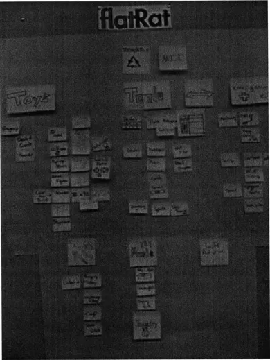
After our brainstorm, we reflected on all of the ideas and evaluated the results. The first step in this process was to categorize the ideas and focus on the areas that we saw
Figure 6: Collection and categorizing of ideas from Brainstorm in Figure 5
From these results we could then go onto deeper evaluation and begin to down select to a concept that we wanted to go forward with. The ease and success of concept selection directly relates to the ideas generated from these early stages.
2 CONCEPT SELECTION
With a multitude of ideas from the brainstorm, we needed to evaluate each in order to move forward with the project. Unlike most concept selection in industry, this down selection mainly revolved around personal affinity for a concept. It was decided that whatever project I went forward with would have to be one that I was passionate about and would be motivated to continue. All of the other constraints and factors could be figured out, but if it wasn't a project that we were excited about it would have a lot more trouble getting off the ground. Most of the time selecting a concept revolves around market potential, technical feasibility, or cost, but with ours we tried to make it fairly personal. There was definitely consideration into every one of these factors and they did contribute to our final concept, but the over arching factor was our excitement.
2.1 THE "FLATRAT"
The clear favorite of our ideas was the concept of a foldable "Brass Rat", MIT's class ring. The ring could be carried around as a credit card sized insert in your wallet and when the time came, you could take the flat ring out, fold it together, and sport a the 3D ring. The ring had the potential to be made out of paper, plastic and most ideally thin metal to give the same aesthetic as the official class ring.
This concept was the most compelling because of the rich history and culture within MIT and behind the "Brass Rat" ring. The "Brass Rat" has been the official class ring of MIT students since 1929 and has become one of the primary recognition symbols of a MIT graduate. The original Standard Technology Ring depicted a beaver, the school's mascot, on
it's bezel which eventually lead to it's nickname the "Brass Rat". Every graduating class of MIT assigns a committee to redesign the ring to be unique to their class. Over the years, the tradition behind the ring has grown and it has become one of the defining elements of all of
MIT.
Though the ring changes every year, there are common elements that make the ring recognizable. This includes common images of a beaver on the bezel, seal and dome on the sides, and most recently the Boston and Cambridge skylines. The Class of 2011 Brass Rat is
Figure 7: The Class of 2011 Brass Rat ring
The foldable Brass Rat concept, known as "flatRat" is an opportunity to celebrate the
rich tradition behind the ring and commemorate the history of MIT. This product focused on the emotional ties that people had to MIT and their rings, which would make our product a
compelling novelty. The actual function of the product is over shadowed by the excitement around it's ties to MIT culture and community.
One of the most compelling parts of this project was our accessibility to the market. With most products, it is difficult to get your foot in the door with a product and capture a market share. This product however was all within reach with the community that we were working in. I also had a lot of the insight into the market, which would allow me to develop the product with clear information and also the ability to do direct user testing to optimize the design. That being said, there were some major trade offs to the MIT market, mainly in size. We could access it easily but we were also caping the size of the project to the size of the small market of the MIT community. For a student project and my first attempt at
product design, this wasn't as much of an issue but rather was a good fit for my abilities. Overall, this concept had a ton of potential to go in lots of different directs with numerous pros for its development in our process. The project also played a good balance of ambiguity for what it could become and enough definition that it could thrive within our
process. With the concept decided, we began the early stages of prototyping and refining the concept to a marketable product.
3 Prototyping
After down selecting to a final concept, I began to prototype to a final product. The flatRat concept was a great fit for prototyping because the idea was open to a multitude of approaches, forms, structures, and issues that could be hashed out during prototyping. Our initial prototyping processes are extremely cost effective and accessible, with everything being free or within a common household.
Our primary goal in the first weeks of prototyping were to develop as many ideas as possible, with as much spread and diversity among the prototypes that we could think of. This would lead to a wide range of elements that could lead to a breakthrough in the final iteration of the flatRat. Since the first stages of prototyping took relatively no money and little time, not all the prototypes I made necessarily made sense as a final product. Some would
be very difficult to use, manufacture or distribute, but they each an interesting element that I hadn't seen in previous prototyping. With low fidelity prototyping, this mindset is incredibly
important for (1) potentially finding an innovative solution and (2) understanding everything
about the materials and constraints of the prototyping process. By pushing each prototyping tool too its boundaries, we could see what the most extreme prototype of flatRat may look
like and how that may translate into an interesting product.
3.1 VISUAL PROTOTYPING
Our prototyping process began with the lowest fidelity tools and advanced to more complex as we felt necessary. The lowest form of prototyping is through sketching or basic digital rendering. Drawing a form, idea or structure can give you pertinent information a very small amount of time put into the sketch. Putting ideas to paper creates a concrete visual for a concept and is the first step to understanding if it can be translated to a tangible prototype. Sketching allows for quick iteration but it also doesn't allow you to understand the physical constraints of the project or the potential issues of the forms represented. It does provide a great first representation and can serve as an invaluable first tool to bringing any idea to life.
The next level above this is digital rendering, which in some forms can take just as little of time as drawing out an idea. Digital prototyping is helpful because it allows the visual
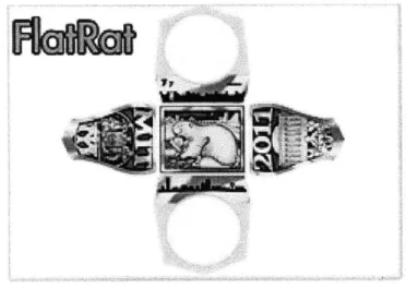
prototype to take more complex forms at a high resolution. For example, I can attempt to draw a perfect square by using a ruler, measuring out exact side widths, make sure the corners are exactly 90 degrees, and try to get it exact with pen along those lines. This will lead to a good looking square, but there are too many potential inconsistencies to make sure that it is perfect. Digital prototyping will take away the human tolerances and make the square precise. It also has the ability to add complex coloring, abstract curves, and is editable after its creation. There are a wide range of tools to use on the computer for this and even the easiest to use can give a great visual prototype for a short amount of time invested. Figure 8 shows a digital prototype of the flatRat before anything was actually prototyped physically.
Figure 8 Digital prototype of flatRat concept created in Adobe Photoshop CS3. June 2009.
Figure 8 was created using Adobe Photoshop CS3 but it's components can all be made by MS Paint or other standard software. I was able to include all the basic form elements of a flat ring while also adding the components of the 2011 Brass Rat to give it a completed feel. This digital prototype gave a quality first representation and would in turn influence future prototypes.
3.2 PAPER PROTOTYPING
Paper prototyping is one of the quickest and cheapest form of physical rapid prototyping. Paper lends itself to many functions and with the flatRat project, paper's properties can be directly related to tho materials that we were hoping to use. This form of
prototyping serves our overall projects goals as well. By restricting to 2 dimensional manufacturing, we can essentially reproduce any part with paper or paper based products. Some of the material properties may differ from some of the material options we were considering, like metals or plastics, but all the forms can be modeled and rigid card stock
can be used that hold shape to mimic stronger materials.
Paper can be cut and manipulated very easily which allowed us to create dozens of prototypes in a very shot amount of time. This process allows for continuous iteration and improvement, which can't be said for a lot of prototyping processes. If we chose to prototype in metals at this stage, each prototype would have a considerably larger investment. This would require us to make more concise prototypes and leave less room for exploration, which was critical in the early development stages of our product. With very little investment, we had huge returns for what we learned in paper and the beginning of our physical
prototyping.
The very first physical prototype seen in Figure 9 of flatRat is a prime a low fidelity prototype can prove as a proof of concept.
example of how
Figure 9: Rough prototyping of digital prototype in Figure 1. Made out of wax coated playing card. Flat packed form (left) and comparing shape to brass rat (center) on finger (left)
This prototype took less than 10 minutes to make but it yielded a basic proof that the form in Figure 8 made sense as a physical product. It also required no monetary investment
by being made out of a recycle playing card.
Continuing on this path of taking a digital design and turning into a physical prototype, I wanted to see what kind of shapes and complexity I could get with the computer and transfer it to paper. With these prototypes, I set a constraint of using only open source computer programs, meaning that they are complete free to download and use. This was in
line with our original philosophy of accessibility and cost effectiveness.
The first program I explored was Metasequoia, a japanese surface modeling program that runs on Windows. It allows you to create and edit objects based on flat surfaces. For example, a cube won't be a solid volume but rather a collection of 6 flat surfaces. This works perfectly for paper based prototypes that can only use a flat surface in order to The language barrier from its translation is difficult at times, but for the most part everything is universally designed so that anyone can use it. I was able to prototype several three dimensional mockups of flatRat in the software, the first shown in Figure 10.
This model gave us a good idea of the shape and look of a 3D ring, but a physical prototype would provide tangible feedback for this model. To make a paper prototype, I could have done extensive geometry analysis and precise measuring and cutting, but that would take far too long for the fidelity of prototype we were looking for. Instead, I found the free program "Papakua" (Figure 11) which takes the surface models created in Metasequeria and unfolds them to paper cut outs. So the complex surfaces made in the original model will be folded out, given flaps, and fit onto a standard pieces of printer paper.
FIGURE 11: Computer aided "unfolding" software Papakura screen shot
I could then print this out onto standard computer paper from a generic printer, cut
with an ulfaknife and fold together. This model, shown Figure 12, was fairly complex in geometry and took some dexterity to assembly. This process allowed for some very detailed prototypes that had much more complex of geometries to the point where it was too difficult to reproduce by hand. This also had a great potential of turning into a final form of the flatRat with the ability to fold together a full flatRat with a cheap and easy piece of paper.
FIGURE 12: Prototype derived from Figure 11 and assembled with paper, ulfaknife and glue. June 2009.
This tool helped create a series of prototypes in a short period of time. Each of the prototypes attempted to have some differentiating factor that would allow us to learn something from each one. The prototypes in Figure 13 is testing the ability to transfer this technology to the size constraints of the rings. These two prototypes approximated a size nine ring and also the ability to include artwork.
FIGURE 13: Small prototype derived from Papakura software with added graphics (left). June 2009.
These two prototypes required an even greater amount of dexterity to assembly. They turned out to look very similar to the Brass Rat look and feel but were pretty hard to put
together, which was a constant trade off that we had to make throughout the process with future prototypes.
The prototype in Figure 14 attempts to diffuse the difficulty of these types of paper prototypes and keep the look and feel of the ring. The ring is broken into 3 components that are individually easier to fold than than the whole ring shown in Figure 4.
FIGURE 14: Multi piece large ring modeled by Papakura software with added graphics. June 2009.
This prototype was the first exploration into a multiple piece ring. This made each piece easier to fold but several potential issues arose based on the multiple piece component . The most obvious problem was how each piece would interact with one another, especially in the final product. This prototype could be glued together but that solution would be impractical for user assembly. The question continued to be an potential problem for any approach with multiple pieces and would lead to some interesting solutions down the road.
After quickly exploring the multiple part ring, I dove back into creating a ring that would function from a single part. This would help us avoid the connecting issue and also aid in some other factors like keeping multiple parts together in packaging and distribution. I
began to look into different forms that would be replicated if the product would be made out of metal. This would require much simpler folding methods than the previous prototypes but also wouldn't require and fasteners or glue to maintain their shape.
The prototype in Figure 15 demonstrates a paper prototype that would take advantage of the characteristics of metal and also beginning to address the issues of a multiple finger sizes. This ring would be bent to a basic shape down from the bezel, and then points that would meet under the ring would be adjustable. This would allow a large range of fingers to use the same ring and individual sizes wouldn't have to be made.
FIGURE 15: Paper prototype with adjustable flaps for multiple ring sizes. June 2009.
Though this prototype looked to address some of the primary needs, it fell short in giving a good feel. It did however, help stir the issue of multiple sizes and how we were going to address the problem of fitting the ring to many people.
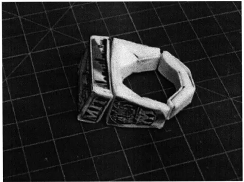
The prototype in Figure 16 continues with the theme of one part prototyping. This is a similar prototype to the previous CAD based rings, but I looked to minimize the amount of material used with the shape. This prototype was considerably easier to fold together than
the previous prototypes and it had a great feel once it was completed. Overall, this prototype had a lot of positives and lent itself very well to the overall concept of flatRat.
FIGURE 1.6: One piece prototype derived from Papakura and assembled with glue. June 2009.
The main issues with this part were its size and again, the issue of multiple sizing. At this point in the project, we were looking to fit the entire product in someone's wallet and this prototype was double the allowable length. The issue of multiple sizes wasn't served in this prototype but its form gave rise to a potential solution of changing the band length to change the sizing. The long tail seen in this prototype could easily be shortened or lengthened to fit anyone's ring.
To build upon this concept, my next prototype looked to serve multiple sizing while maintaining the form of the ring. I also began to look more closely at what makes the look
and feel of the Brass Rat unique and how to implement those aesthetics with the
functionality that we want for our product. One of the most defining components of the ring is how the bezel interacts with the rest of the ring. There is a distinct ridge that borders the main beaver depiction and the inset bezel is a unique feature that people can recognize from a distance. I also questioned some of the form elements needed on the flatRat, in particular needing full form around the bottom of the ring. The underside of the ring is rarely
looked at and if someone is showing off a ring, they exclusively display the top side of the ring with your other fingers covering the bottom side of the ring. With those thoughts in mind, I made the prototype shown in Figure 17 in CAD.
FIGURE 17: CAD of more complex multi piece prototype. June 2009.
This prototype stepped back into multiple pieces in order to gain all the functionally that we wanted. I also emphasized the need for all the surface to be able to display the full artwork of the ring along with the raised ridge bordering the bezel. The full assembly of the ring is shown in Figure 18 from 3 pieces to a comparison to the Brass Rat.
FIGURE 18: Physical prototype from CAD in Figure 17. Product assembly cycle from top left. June 2009.
This top side of this prototype was the most similar to the Brass Rat along with having the potential to serve different size of rings. The prototype requires assembly and each piece is connected strictly by mechanical functions of either hooking or press fits. It met a lot of our constraints, but it had the issue of a large surface area needed for the complete product. Though the bottoms side served a primary function, there was something missing about the look and feel of the ring. If it wasn't on your finger, it would look incomplete and unrefined. We were assuming that people would wear the ring for a few minutes, but the rest of the time it would serve as a novelty item that was fun representation of MIT. This brought up the issue of how complete the product had to look and the balance between functionality and aesthetics.
Figure 19 dives into the functional side of this argument by attempting to again satisfy our issues with variable sizes. The basic bezel was fit with a rubber band that would conform to the complete range of finger sizes.
FIGURE 19: Basic bezel and rubber band prototype. June 2009.
This solution was great to include all of potential market with one ring but it also had some big issues with implementation and aesthetics. The biggest downfall of this prototype was how we would be able to implement this function easily within our manufacturing and assembly steps. We would have to source an entirely new manufacturing process and then would have to assemble the product accordingly, or find a way that users could easily put it in place. Even if we did have the users assembly the product we would still have a more complex packaging process that would have to include the multiple forms and materials.
The next few prototypes were an attempt to completely step away from the techniques that I had previously been working with and potentially find a new solution to our problems. Figure 20 shows a quick prototype into foam core, a thicker composite material made of paper and foam. This prototype was definitely difficult to work with and the end product showed the results of that. In order to work with material, our manufacturing process would have to be very detailed and controlled to get quality edging and form. Overall, this quick
prototype gave a quick indication that working with this material would probably be a bad decision.
FIGURE 20: Foamcore prototype. July 2009.
On a similar path, Figure 21 is an exploration into 3D materials to see if there was anything interesting to learn from those types of forms. For these prototypes, I carved blue form to the form of the rings. One prototype was left whole while the other was cut to smaller pieces for potential assembly. This process was tedious and without the correct tools, the prototypes turned out to be pretty rough and unfinished.
Ultimately, both the foam and foam core were difficult to work with and the prototypes that each yielded were poor. This helped us narrow our potential materials and where I'd focus the next set of prototypes. This also was a quality lesson in exploring different materials within prototyping. By quickly incorporating these two prototyping materials I could easily see that they were a poor fit but also a sense of what kind of projects that might be suitable for the in the future. These two prototypes took very little time and gave me a lot of information, which is incredibly valuable for the prototyping process. These two prototypes
really didn't contribute anything to the end project, but served as a great, quick learning tool for the prototyping process as a whole and the focus that lead to the future quality
prototypes.
After this divergence, I dove back into exploring paper prototypes. With previous prototypes, I was able to see a lot of how I could incorporate all the aesthetics we may need for the project but there were still plenty of questions involving the best way to attache the functional requirements of the ring. Figure 22 shows an attempt to attach to pieces of the ring mechanically. The ring has two tabs on either end that can be placed through a slot, turned 90 degrees and pulled back down into slots that hold the two pieces together.
FIGURE 22: Ring locking mechanism for multi piece rings. July 2009.
This prototype started pushing forward to solve our problems with more mechanically complex solutions than simple folding and cutting. These solutions are more robust and can
be done in a multitude of ways to serve all the functions I was looking for in the ring. This solutions isn't necessarily optimized or the best, but it served as a good starting point for the
prototypes to follow.
This time frame of prototyping really pushed my creative abilities to think of solutions far outside of the box. By trying to find non-obvious solutions or unorthodox approaches, I started to come across more interesting ideas and more compelling concepts. This started showing the value of repeat prototyping and diversify approaches. With a steady set of various prototypes, each mandated to take a different approach, I was able to see the real
boundaries of the process and also how to play within the space to come up with a novel solution.
My next prototype really exemplifies the prototyping process by its unique and
non-obvious solution. The goal of the prototype in Figure 23 was to simplify the entire product down to a rectangle. I was only able to use a 90 degree rectangle in order to create a full ring shape. I also wanted it to be a continuous ring that didn't require complex connecting points. This lead to a prototype that would be easily folded and robustly stay together. The prototype when worn would display the shanks and bezel fully and the supporting ring held the rest of the ring together without interaction points.
This solution lacked in some areas of concern such as a ring look in every component, with an aesthetically lacking underside. This was countered however with the simplicity of the prototype and also the saved cost with the initial form. This prototype, if produced, would be the cheapest to manufacture and would yield a great look and feel. It fits all of our constraints to fit in the form factor of a business card and wold be a great addition to someone's wallet. With paper, it has the ability to be refolded and re-worn, something not many of the prototypes have. Though I liked this prototype, I had to continue to diversify and explore to potentially see something new and interesting.
The prototype in Figure 23 inspired to me to push the envelope on simple forms moving in ways that you wouldn't expect. We also had discussions as a group about the potential functionality of the flatRat and the possibility of making it more puzzle like. Instead of using intuitive forms, the product would be non-obvious and challenge the user to put it together the right way. Though the end product still looked to deliver the same thing, getting to the final product would be more interesting and complex user experience. Figure 24 shows my attempt for a puzzle ring that requires some non-obvious folding and interactions that gives both an interesting look and more intricate final product.
This prototype was both interesting and insightful. Most of the time, you want to make a product easy to understand and come together with simple and obvious steps. This however, required me to make something more complex and more difficult to user in order to add to the user experience of putting it together. Eventually, we decided this strategy added a little too much complexity for what we were ultimately trying to do, but practice this process and looking to control the user experience in a certain way was very valuable for future prototyping.
Paper prototyping served as an incredibly useful resource and created a great foundation for the project, all while costing less than 5 dollars for all materials used. The value gained from these prototypes greatly outweighed the investment and served as the perfect spring board to the next level of prototyping. It was also all done with tools that anyone can access and use, providing the perfect platform for anyone to use and exploit for our development process.
3.3 LASER CUTTING
Laser cutting is a quick, cheap (for this particular project) and informative prototyping tool. The machines have a wide range of capabilities ranging from cutting surface imagines on materials to creating complex 2 dimensional curves in mechanical products. The laser cutter was our initial end manufacturing process and the constraints of the machine created the initial constraints on our process of 2 dimensional products. This prototyping process served as a great tool for our prototyping by including the detail of computer aided design paired with computer controlled machining. This allowed us to prototype with controlled variations but also consistent repeatability that we would need for future manufacturing.
A laser cutter works by controlling the power of a laser to a single point and being
able to move that point over an x-y plane. The concentrated energy in the laser is focused to point on a material and the energy separates the molecules within the material.. This separation, when done so through the entire thickness of the part, is called a vector. Vector cuts can be complex shapes on the x-y plane or cut holes on the interior of a flat part. The power of the laser can be limited so only the surface of a material is altered, which is called
a raster. This effect can be used to add images or basic functional features that require basic multiple thicknesses. Raster cuts have a great amount of variability however, and shouldn't be relied upon for tight tolerances.
Just as paper prototyping, all of the initial pieces must be 2 dimensional. When designing 3D products with the laser cutter, the object should only consist of 2D flat planes and then assembled into the 3D product. This again brought up the issue of interacting pieces and how to design the connection points which will be discussed further in the paper. The use of the laser cutter requires some more advanced computer programs in order to translate designs into the laser tool paths. The major requirement is a vector editing software, such as Adobe Illustrator or CorelDraw. The program must be vector based, which means it develops an image based on a set of equations rather than pixels. For example, when you draw a line, a vector creates an equation for that line to exist rather than a pixel based software would simply color the pixels in the path a different color. This allows the line to be edited after being created along with creating an equation that can be translated into the laser's movement when cutting.
These programs only allow you to edit 2D parts from a top view and you can't develop the more complex 3D products that the project may be looking for. In order to edit these parts, I used solid modeling software "Solidworks" which can control the thickness of the parts and the interaction between the parts can be modeled. This program has the versatility to create complex assemblies for more advanced prototypes that we couldn't get with vector based programs.
Using both Solidworks and Adobe Illustrator took a specific process in order to translate the files into data that could be used for the laser cutter. Appendix B outlines the
necessary process to get the files from these programs to final cut on the laser. There are some portions of this step by step process that can cause issues within the final cuts so by creating a defined set of steps, one can always easily cut files from these formats. It is also possible to cut from many other formatted files as long as they can be opened with CorelDraw for this particular laser cutter.
For more advanced prototypes and to limit the use of glue or other fasteners, I developed a way to snap together pieces with flush edges. This is done with a pressure snap fit with a hook shape on one piece, with ridges to snap into on the other piece. These snap fits can be used for 90 degree joints. This doesn't mean the object is limited to right angles, but there must be a 90 deg angle where the two pieces meet one another.
A basic design diagram is given in Figure 25 with relevant dimensions. The raster
areas will require testing based on the quality and strength of the laser cutter that is used in order to get a .005" deep raster cut.
Raster W = with of hole 2,3
Vetor ta = thickness of snap side t
th = thickness of hole side
W +.01
FIGURE 25: Acrylic snap fit feature for laser cut prototyping
These snaps can be used individually but are best when used in pairs. In order to use a pair of snaps, set up the centers of of the snaps to align with their matching hole/snap as shown
FIGURE 26: Acrylic snap fit alignment for multiple features
The holes can also be used to get a completely flush corner by moving the features to the edge of each piece. If the tolerances from the machine are tight enough, these edge
holes will be robust for most applications but have more potential for falling apart.
A plus to laser cutting is that you are able to create images by way of rastering. This
can create a binary image, which means there can only be two different levels of contrast. This means your image is created with a series of cuts that are all of the same depth. Some
lasers have the potential to differentiate rastering thicknesses for a more detailed depth profile in an imagine, but none of our testing included these features. There is a limit to the complexity of the images used, but by adding images by laser saves a secondary manufacturing process to add graphics.
3.4 LASER PROTOTYPING
Prototyping flatRat with a laser presented unique challenges for the form and aesthetic of a ring. The first prototypes were bulky and a far way off from a real Brass Rat look and feel. This was a result of the plastics that we were using and their lack of dexterity for this application. After exploring with the basic functions of the laser and getting the basics of a snap fit to work, I produced the first iteration of flatRat in plastic as seen in Figure 27.
FIGURE 27: Acrylic multi piece prototype with adjustable band and rastered bezel images. July 2009.
This prototype is a total of 8 pieces that are easily assembled and fit together to be a
wearable ring. It is primarily made up of two different thicknesses of acrylic sheet and the
band is a nylon strap. The strap can be adjusted to multiple sizes of finger and easily fits within holes on the underside of the ring. There is also rastered image of a beaver on the bezel to test to capabilities of translating an image to the ring. The prototype fit a lot of the functional requirements of the ring and with a better color of acrylic, it would start looking a bit more like a real Brass Rat.
As we started to increasing fidelity of prototypes, there was a rising problem of how we were going to package all these pieces. For this prototype, I developed a laser cut packaging solution as seen in Figure 28.
FIGURE 27: Packaging prototype for Figure 26 ring. July 2009.
Since this prototype was 8 different pieces of varying thickness, I had to come up with a solution that accommodated that. The package is made up of the thickest piece of
acrylic with those components directly cut into the sheet. The rest of the sheet is rastered half way through in order to nest the remaining components. The entire package was then sealed with clear tape coating to hold everything in place. This solution seemed interesting but it also had some major problems that called for refinement.
The main issue with this prototype was the multiple sizes of acrylic and different material for the band. This would require (1) multiple sources for materials (2) advanced assembly that would take time and money. Though these could all be made on the laser cutter, the whole process of nesting several parts and sourcing assembly would potentially increase cost to the point where we couldn't see any. This prototype also took a lot of time per part to make on the cutter. With the heavy rastering in the material for the nesting parts, each unit would cost too much to actually outsource. Ultimately the product needed to be slimmed down, reduced part count and aesthetically refined.
One of the more difficult issues with the laser cutter was getting quality images with the rastering. Figure 28 shows some explorations in imagine application strategies with different materials.
FIGURE 28: rastering testing on acrylic mirror (left), opaque acrylic (center) and backside rastering on clear
acrylic (right). July 2009
One of the major tactile factors on the real Brass Rat is the depth and profile of the beaver on the bezel, so I did my best to replicate that in the initial prototypes by rastering on the top side of the acrylic. This would give a rough surface and basic depth to give a similar feel. This however, would require very deep cuts that would at times start melting the surrounding plastic, leaving a dusty residue and burn marks. In order to mitigate this problem, I optimized the boundaries of the raster on the laser I was using. This was part of a trade off of aesthetic feel and time per cut. With deep cuts, the machine would take a lot longer to lay a depth heavy imagine compared to a quick cut image that may lose some of it's appeal.
I attempted to find some new solutions among different types of acrylic and different
application of the laser. The first was a backside cut on the translucent plastic which shows the image of the ring through the clear plastic. This gave a clean topside view but also took away from some of the look and feel we were going for. I also tried top side cut on opaque acrylic to see how the different contrast would help the look. The image came out clearer due to the dust residue after the cut but could be wiped away and the image was very
difficult to see. The last was cutting an image into a mirrored back piece of acrylic. This acrylic is covered in a reflective paper that shows through the translucent acrylic and gives a mirrored look. By rastering the paper, the image would come out clear with a much shorter cutting time. There was however some difficulty getting consistency with the cut along with easy burning of the reflective paper.
In general, producing a quality image on the ring was very difficult. The constraints of the laser made it tough to get a good look and tactile feel, but some of the solutions were good enough to get our basic prototyping aesthetic across. I started looking into some other secondary processes like screen printing or painting to get the images on the ring with the
hope to find an interesting solution to this dilemma.
The next set of prototypes looked to redesigning our system for addressing multiple finger sizes. Figure 29 shows the same ring design altered to fit three ranges that covers
95% of the current population. Ring's were sized a 6, 9, and 12 or small, medium and large
respectively, with the hope that people could buy the ring that was slightly larger than your size. This was justified by the user's time actually wearing the ring. If a user only wears the ring from a couple minutes to at most a half hour, having a ring slightly larger would be acceptable. The rest of the time would be enjoying the ring as a novelty. This allows us to tool and stock 3 sizes instead of 24 half incremental sizes that most rings are sold in.
These rings along with a more refined form, also reduced the total part count from 8 to 5. There were still two different thicknesses of acrylic but the nylon strap was removed which takes a considerable additional cost out the product. As this prototype developed, we began to explore some different materials for the bezel including the mirrored acrylic and opaque colored acrylic as seen in Figure 30.
FIGURE 30: Incorporating opaque plastic (left) and mirror acrylic (right) into ring prototype. July 2009
As I prototyped, the team thought it would be fun to explore what a giant Brass Rat would look like and the novelty of having more of a desktop ring as seen in Figure 31.
These prototypes allowed us to develop a lot of little concepts with a simple form, but there were still some fundamental issues that need to be resolved with the form and aesthetic. This prototype would stick out when worn and really didn't have the full Brass Rat feel that was wanted. The bezel appears too squared off and didn't flow well between the bezel and the rest of the ring. This was especially apparent in the smaller rings where the sizing of the bezel over powered the base of the ring. The next set of prototypes looked to really attack the form of the ring and try to bring more of the spirit of the Brass Rat into a plastic flatRat.
FIGURE 32: Reformed ring prototype to more closely resemble form of Brass Rat. August 2009.
Figure 32 shows a first attempt at finding a form factor closer to the Brass Rat. The shanks of the ring were angled out and the snaps to the top bezel piece to the skanks were removed. This lead to the hole and snaps to the sides to be moved lower and flare out on the edges, which was a bit awkward and bulky. The biggest difference was in the transition from the bezel to the lower parts of the ring, which became much smoother and much more Brass
Rat specific.
Building on the foundation of this prototype, I immediately reworked the design and developed the prototype seen in Figure 32. The biggest improvement in the new design is the connection between the ring sides and the shanks, which instead of a snap and hole
mechanism was replaces with a dove-tail like snap system. The alternating posts snap together to give a clean and strong edge to the ring and gave more versatility to the form. The lines and curves of the ring were modeled heavily after the ring and as seen in Figure
33, it began to resemble the Brass Rat profile.
FIGURE 33: Reformed ring prototype with new snap fit edges. August 2009.
This prototype was definitely the best yet and gave the most potential for a viable product. It was also designed to be all one thickness of acrylic so it could be packaged in the same sheet it was cut, removing several steps in the manufacturing and assembly process. Figure 34 demonstrates a mockup of this prototype to be complete cut as one piece on the laser cutter.
The pieces are held in by small tabs connecting the large piece to each piece of the flatRat by simply leaving uncut portions around the circumference of each piece. The card is
similar thickness and size to a credit card and could easily fit in anyone's wallet of pocket. This prototype gave all the functionality, looks and manufacturability that the project was looking for. The only question was whether the laser cutter is ultimately the best strategy or if we even wanted the product to be in plastic. As we continued exploring, we found that it proved to be very expensive and lower quality than what we could achieve.
4 CHEMICAL ETCHING
4.1 DESIGNING FOR CHEMICAL ETCHING
Chemical etching is a 2D manufacturing process that uses chemicals to remove specific areas on sheet metal in order to create complex forms that would be difficult to
machine. It begins with an art proof with a desired image or part. This image is then translated to a protective film and where the image designates there will be a hole in the protective film. This film is then put over the desired metal and then put into a chemical bath. The chemical will react and dissolve the metal at all the open areas of the film. The result is a metal sheet with the art work imprinted onto it.
There are a few options when creating the artwork for chemical etching. You can etch on the front of the sheet, on the back, or etch all the way through. Depending on the thickness of the sheet, there are limits on the resolution of the artwork due to isotropic properties of the etching process. Isotropic etching means that as the chemical dissolves down from the initial film layer, it also etches laterally that affects the resolution of the etch.
FRONT FILM METAL SHEET
BACK FILM
TOP ETCH BACK ETCH FULL ETCH
ISOTROPIC
RESOLUTION LOSS
FIGURE 35: Section view of chemical etching process for back, front and full cuts on metal.
Due to the capabilities of the process, the artwork is essentially limited to "black and white" meaning that either you have a mark or you don't. All complex images must be broken down to two tones, there is no in between "grey". It is also difficult to use both sides of the a sheet for imaging the same area. If you have a front etch on one side, you cannot have any etch on the back or it will become a full etch through. Essentially, you are cutting half way through on either side and when they overlap it etches all the way through. Below is an
FIGURE 36: Chemically etched business card for MIT Mechanical Engineering
As you can see, everything on the card is either etched (matted grey look), etched through("MECH"), or unetched (polished areas). There are several techniques that help make more complex and interesting images with only using these three depths of cut:
- Etching Artwork - You can simply etch the vectors of you images or text directly in. It gives
the cleanest and highest resolution lines. On a 0.01" thick sheet, all vector lines must be at least 0.5 pixel width.
- Etching Background - As seen with the three pillar logo, the artwork is raised from an
etched background. This gives a "popping" look to the artwork and the matte finish of the
etched background gives a good contrast to the card. All raised artwork must be 1 pt width. - Full Etch - Full etching, as seen with "MECH", cuts the artwork all the way through the sheet. It is important to maintain structure when creating full cuts, because if the art is too complex or you have surrounded an area in full etching, it will fall through and you won't get
the desired outcome. Lines that are smaller than 1 pt. between two areas of full etching
will be lost and all "islands" surrounded by full etching should be supported.
In order to develop the artwork for this manufacturing process, I used Adobe Illustrator. It was perfect for creating vector based images which are required for the manufacturer to
![Figure 3 :Mikro Man figure "Off Road". Begins flat and folds up to figure on bike [5]](https://thumb-eu.123doks.com/thumbv2/123doknet/14203703.480481/10.918.219.680.314.621/figure-mikro-man-figure-road-begins-folds-figure.webp)