READ THESE TERMS AND CONDITIONS CAREFULLY BEFORE USING THIS WEBSITE. https://nrc-publications.canada.ca/eng/copyright
Vous avez des questions? Nous pouvons vous aider. Pour communiquer directement avec un auteur, consultez la première page de la revue dans laquelle son article a été publié afin de trouver ses coordonnées. Si vous n’arrivez pas à les repérer, communiquez avec nous à PublicationsArchive-ArchivesPublications@nrc-cnrc.gc.ca.
Questions? Contact the NRC Publications Archive team at
PublicationsArchive-ArchivesPublications@nrc-cnrc.gc.ca. If you wish to email the authors directly, please see the first page of the publication for their contact information.
NRC Publications Archive
Archives des publications du CNRC
This publication could be one of several versions: author’s original, accepted manuscript or the publisher’s version. / La version de cette publication peut être l’une des suivantes : la version prépublication de l’auteur, la version acceptée du manuscrit ou la version de l’éditeur.
Access and use of this website and the material on it are subject to the Terms and Conditions set forth at
The NRC 3-D Laser Tracking System: IIT's Contribution to the
International Space Station Project
Blais, François; Beraldin, Jean-Angelo; Cournoyer, Luc; El-Hakim, Sabry;
Picard, Michel; Domey, Jacques; Rioux, Marc
https://publications-cnrc.canada.ca/fra/droits
L’accès à ce site Web et l’utilisation de son contenu sont assujettis aux conditions présentées dans le site
LISEZ CES CONDITIONS ATTENTIVEMENT AVANT D’UTILISER CE SITE WEB.
NRC Publications Record / Notice d'Archives des publications de CNRC:
https://nrc-publications.canada.ca/eng/view/object/?id=eecfebed-ba51-4b6d-9121-13b8d94018e1 https://publications-cnrc.canada.ca/fra/voir/objet/?id=eecfebed-ba51-4b6d-9121-13b8d94018e1
National Research Council Canada Institute for Information Technology Conseil national de recherches Canada Institut de Technologie de l’information
The NRC 3-D Laser Tracking System: IIT’s
Contribution to the International Space Station
Project*
F. Blais, J.-A. Beraldin, L. Cournoyer, S. El-Hakim,
M. Picard, J. Domey, and M. Rioux
April 2001
Copyright 2001 by
National Research Council of Canada
Permission is granted to quote short excerpts and to reproduce figures and tables from this report, provided that the source of such material is fully acknowledged.
*
published in Proceedings of the 2001 Workshop of Italy-Canada on 3D DigitalImaging and Modeling Application of : Heritabe, Industry, Medicine, & Land. Padova, Italy, April 3–4, 2001. NRC 44181.
The NRC 3D Laser Tracking System: Contribution to International
Space Station Project
*F. Blais, J.-A.Beraldin, L. Cournoyer, S.F.El-Hakim, M.Picard, J.Domey, M.Rioux
National Research Council of Canada
Institute for Information Technology
Ottawa, Ontario, Canada, K1A 0R6
Francois.Blais@nrc.ca
ABSTRACT
Advances in the 3D sensing of dynamics and unstructured environments require the development of intelligent systems, algorithms, and methods to replace or at least minimize the human intervention to the 3D acquisition process. From the user point of view, most existing 3D acquisition systems still require static techniques that can be considered archaic when compared to current 2D still cameras and video. For dynamically uncontrolled environments, the dynamics of the 3D system is becoming very important. Space applications provide an initial impetus to reach this objective, for uncontrolled and harsh environments. This paper will summarize the work that the National Research Council of Canada has pursued in the development of sensing, dynamic tracking, and intelligent acquisition systems for space applications.
1. INTRODUCTION
Presently, the process of 3D sensing still requires static rigid scenes, and complex equipments. Looking at the end results and comparing 3D acquisition methods with the more conventional 2D still and/or video cameras, we can immediately see that research is still needed to obtain the equivalent of ease of use of the 2D video and still camera counterpart. Research in 3D is limited by key factors: (1) 3D is an emerging technology and therefore does not have the same large consumer market and momentum that 2D still-imaging and video cameras enjoy, (2) the fields of applications are very specialized and requirements are often contradictory, and finally, (3) cost and complexity. To define research content that is at the same time specialized and generic is difficult but challenging and rewarding. Cost reduction is an important economic topic and researchers at the NRC and elsewhere have demonstrated different acquisition methods that offer the potential of low cost; the Biris and BiView sensors are two examples [1]. Although volume production and market are still important factors that prevent a real cost effective 3D solution, this is also rapidly evolving.
During the late 80s, the 3D laser scanner systems developed were mostly limited to laboratory use and commercial systems were focused toward very specific applications such as the automobile industry. In the early 90s, a mobile (to differentiate with portable) version of the auto-synchronized scanner was demonstrated, first for the acquisition of a scaled model of the cargo bay of the space shuttle [2]. In the mid-90s, the scanners are moved in the field with experiments in Israel, on Canada’s Parliament Hill, and in Kennedy Space Center Florida, USA. With the development of the Biris portable sensor, cost effective experiments in Italy were made possible; a first in portable 3D equipment [2-3].
Advances in the sensing of dynamics and unstructured environments are still at the early research stage and require the development of intelligent systems, algorithms, and methods to minimize the human intervention. Because these intelligent systems are at the very early stage of development, cost justification of the research, prototypes, and the definition of the application, to narrow down the research objectives and expectations, are key questions. Space provides an initial impetus to reach this objective.
• Tracking and acquisition of dynamically moving objects.
• Study of the dynamics of the sensor and of the acquisition process.
• Smart intelligent acquisition systems for dynamic and unstructured environment.
*
2. THE NRC AND SPACE
Canada plays a very important role in the Space Program and the National Research Council of Canada (NRC) has been a key player in Canada’s contribution to the space initiatives. The robotic Canadarm, for example, is a technology whose origins are directly linked to NRC labs. Another key technology is the Space Vision System used on-board the Space Shuttle. Neptec Design Group manufactures this advanced space qualified version of a prototype system originally demonstrated at NRC in the early 70s.
In 1989, the Canadian Space Agency was created to supervise and coordinates Canada’s efforts in space. For the new International Space Station, one of Canada’s main contribution is the Mobile Servicing System, which will support the assembly, maintenance, and servicing of the space station. Today, the Space Vision System is a key component for the assembly of the International Space Station.
In the early 90s, the Institute for Information Technology (IIT) of the National Research Council of Canada (NRC) successfully demonstrated major advances in the use of laser scanner technologies for space applications. The technique developed combines laser scanning technology, ranging, imaging, and tracking to compute in real-time the pose of objects [4]. This laser scanner was designed to be insensitive to background illumination such as the earth albedo and the sun and most of its reflections. To demonstrate the concept, retro-reflective targets were used and tracking was based on the intensity of the reflected laser light. In the mid 90s, the use of the laser scanner system for the acquisition of dense static 3D views and the integration of these multiple views in a single 3D object, using Polyworks, were presented. During the late 90s, the focus of the 3D sensing research activities was shifted toward portability Biris, quality, and colour. All these combined advances also demonstrated the needs for more user-friendly acquisition systems, better adapted to the ever-changing conditions of dynamic environments.
In the summer of 1999, the laser scanner prototype was successfully interfaced to the Space Vision System [5] with major advances in both software and hardware technology. The prototype automatically searches and tracks in 3D retro targets attached to the object. Stability of the photo-solution was advantageously compared to results obtained using existing video cameras but with the added feature of generating robust solutions in the presence of strong background illumination. With this success Neptec Design Group and the National Research Council of Canada, in collaboration with the Canadian Space Agency, are currently working on a space-qualified version of the Laser Scanner prototype, to be flown on board mission 7A during the summer of 2001.
More recent work has also demonstrated the capabilities of the laser technology to track the existing Inconel Black/White targets making the system compatible with existing NASA equipment, a key feature for acceptance. This research has also demonstrated the first successful results of dynamic controls of 3D scanning, real “real-time” (msec range) geometrical (3D) processing, tracking, and relative pose evaluation of moving object/sensors.
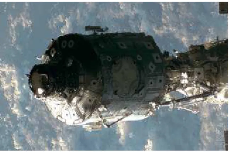
Figure 1. The existing Space Vision System (SVS) uses the known locations of the B/W targets to compute the pose of objects. Effects of sun illumination and earth albedo on video images that affect accuracy and reliability are wide dynamic range, poor signal, saturation, and shadows. (Courtesy of NASA)
Figure 2: Inspection in orbit, a key task for 3D systems. Fine surface details can be accurately monitored and inspected using the 3D geometry. (Courtesy of NASA)
3. SPACE A HARSH ENVIRONMENT
Experience gained in ground simulation and on orbit during space shuttle missions has proved the importance of vision for space applications. As mentioned previously, a key component, currently used by NASA for the assembly of the International Space Station is the Space Vision System. This vision system uses video cameras and photogrammetry-based methods to compute in real-time the pose (position and orientation) of an object [6,7].
Video camera based systems are attractive because of their ease of use, low maintenance, and simplicity of integration to existing equipment. Unfortunately, the presence of the sun or any other strong sources of light adversely affect the quality of the conventional methods that rely on standard video images, e.g. the camera on-board the Space Shuttle. Poor contrast between features on the object and background makes these conventional video images difficult to analyze. Figure 1 shows a typical example of video images obtained on orbit that illustrates potential problems a vision system will encounter during normal operation. Camera saturation, insufficient light and shadows are very serious problems that limit the normal operation of conventional video-based vision systems. An special case for automated machine vision system is concerned with lighting gradients (cast shadows), which requires both extended dynamic range for the video camera and sophisticated image processing algorithms. Although this seems a-priori a
straightforward problem for the human eye (brain), it is not as simple for limited dynamic range vision systems. It is therefore very important that any complementary systems like a laser scanner be robust to operational conditions such as sun interference, saturation, shadows, or simply insufficient light. Figure 2 illustrates the type of inspection task that can be expected from a 3D vision system.
The laser-based range scanner approach presented here offers the advantage of being close to 100% operational throughout the changing illumination conditions in orbit. The technique is designed to be insensitive to background illumination such as the sun and most of its reflections. The laser scanner uses two principal modes of operation:
• Imaging produces a dense raster type 3D (range) image of the object.
• Real-time tracking of multiple targets on object(s): to compute the orientation and position of the object in 3D
space.
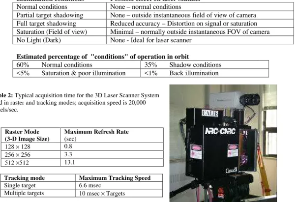
Table 1: Conditions for ambient illumination and their effect on the Laser Scanner System. Illumination conditions Possible effect on laser scanner
Normal conditions None – normal conditions
Partial target shadowing None – outside instantaneous field of view of camera Full target shadowing Reduced accuracy – Distortion on signal or saturation Saturation (Field of view) Minimal – normally outside instantaneous FOV of camera No Light (Dark) None - Ideal for laser scanner
Estimated percentage of "conditions" of operation in orbit
60% Normal conditions 35% Shadow conditions <5% Saturation & poor illumination <1% Back illumination
Table 2: Typical acquisition time for the 3D Laser Scanner System used in raster and tracking modes; acquisition speed is 20,000 voxels/sec.
Raster Mode (3-D Image Size)
Maximum Refresh Rate (sec)
128 × 128 0.8 256 × 256 3.3 512 ×512 13.1
Tracking mode Maximum Tracking Speed Single target 6.6 msec
Multiple targets 10 msec × Targets
Figure 3: Prototype of the laser scanner system, a conventional video camera is “temporarily” mounted on the laser scanner for monitoring and comparison with conventional video methods.
One of the unique features of this laser system is its potential to combine in a single unit different ranging and object pose estimation methods:
• Triangulation-based method for short to medium distance measurements (<5-10 m)
• Photogrammetry-based technique (spatial resection) and target tracking, compatible with current Space Vision System (SVS) used by NASA.
Using the imaging mode, the main applications include inspection and maintenance; where as, assembly, docking, and any tele-operations are solved using the tracking mode. In tracking mode, the variable resolution laser scanner of Figure 3 tracks in real time targets and/or geometrical features of an object as shown in Figures 5 and 10. The scanner uses two high-speed galvanometers and a collimated laser beam to address individual targets on the object. Very high resolution and excellent tracking accuracy are obtained using Lissajous scanning patterns [8]. Laser wavelengths at 1.5
µm (eye-safe), 820 nm (infrared), and 523 nm (green) have been tested.
The Space Vision System [9] tracks the small black dot targets visible in Figure 1. Because the exact locations of these features on the object are known, object position is computed from their relative positions in the video images using photogrammetry-based techniques. Obviously tracking compatibility with these B/W targets is a key aspect for the laser scanner and system sensitivity becomes mostly a question of minimum laser signal power relative to the background light rather than the minimum signal detected and detector electrical noise.
The most recent works use the geometry of simple 3D features such as holes of circular protuberances, sphere. Although this is still limited, it opens the door to fully track the detailed geometry of an object Raster imaging can then be used to obtain very dense images while simultaneously tracking the relative motion of the moving objects or the camera.
4. IMAGING VS REAL-TIME TRACKING
Because of the inertia and limited speed of galvanometers, a 3D laser scanner used in the conventional raster-imaging mode of operation will be very slow. As shown in Figure 4, raster imaging consists of scanning the scene line-by-line, emulating the video reading mechanism of conventional CCD/CMOS cameras. Although video 3D range imaging has been demonstrated [10] using very fast rotating mirrors, maximum range and accuracy measurements are limited and insufficient for tracking. Table 2 shows the speed of acquiring a 3D-range image assuming an acquisition speed of 20,000 voxels/sec. It is clear that refresh rates will be prohibitively slow with conventional raster type images.
Real-time tracking of targets or geometrical features on an object is implemented using Lissajous figures, to obtain good scanning speed and accuracy. Driving the two axis galvanometers with sine waves of different frequencies creates a Lissajous pattern [4,5]. Figure 5 illustrates the geometrical tracking principle using the 3D range information on the Lissajous pattern, to (a) identify targets on the object or any useful geometrical feature and (b) to discriminate the target from its background as illustrated by the bounding box in Figure 5. Lissajous patterns are used to efficiently scan objects at refresh rates exceeding the bandwidth of the mechanical deflection system. The natural inertia of the
Figure 4: Conventional raster type imaging mode. The whole object is scanned line by line and a raster type image is created.
Figure 5: Illustration of real-time tracking of geometrical features using Lissajous patterns. Range information is used to discriminate between the object and its background.
Object Laser Scanner Raster Scan Pattern Laser Lissajous Tracking Patterns Laser Scanner Object Laser Range Validation
galvanometer-mirror structure smoothes the scanning pattern and hence increases the pointing accuracy of the tracking system.
Section 7 will describe the principle associated with position tracking of a single target using Lissajous patterns (Figures 12 and 13). Range and intensity data are measured for each of the N points on the scanning pattern. Both range and intensity data can be used to discriminate targets and background.
5. RASTER IMAGING DEMONSTRATION
Results demonstrating the accuracy of a 3-D Laser Camera build at the NRC for the creation of models and measurements were presented with a test case that was performed in collaboration with the Canadian Space Agency (CSA) and NASA [2,11]. The goal of this test was to evaluate the technology in tasks that will ease the documentation, assembly, and inspection of the international space station.
After acquiring many 3D images all around the Orbital Docking Station (ODS) (Fig. 6), interfacing the MIR station and the Space Shuttle, these images were merged to create a complex 3D model of the ODS at different level of complexity depending on the application. For example CAD (computer aided design) prefers full resolution images, e.g. 10 million polygons. Web pages are limited by the speed of modems and the computing power of personal computers and coarser resolution is used, e.g. 10 000 polygons.
Figure 6: The ODS module at KSC. (Courtesy of NASA)
Figure 7: Scanning the ODS.
Figure 8: Creation of a 3D model of the ODS module.
Figures 7 and 8 show the experiment and the results obtained. There are still several unresolved issues such as the evaluation and selection of the proper views for image registration and object occlusions, however it is worth
mentioning that object model creation has considerably evolved since then and powerful commercial software, such as Polyworks from Innovmetric Software, are now readily available.
6. INTEGRATION OF LASER CAMERA SYSTEM WITH THE SPACE VISION SYSTEM
The demonstration of real-time cooperative targets was the next logical step in the demonstration of intelligent systems. Accuracy and ruggedness to harsh lighting conditions and environments were therefore some of the key questions to answer. The Laser Camera System – SVS demonstration project had two main objectives [5]:
• To demonstrate that the Space Vision System (SVS) accuracy performance, with the Laser Tracking System used as a sensor, is equivalent to the performance of the system using an orbiter quality video camera as a sensor.
• To demonstrate that the LCS provides greater robustness to adverse lighting conditions than is provided by a video camera.
Figure 10 shows the multiple targets tracking process in action where the laser scanner is programmed to sequentially scan different sections of the object. One of the targets is here in the search mode and the scanner uses a larger Lissajous pattern to locate it. When found, the scanner automatically switches from the search mode to the track mode
using a smaller Lissajous pattern to increase target centroid accuracy. Using this method, errors introduced by the measurement process are always optimal because the scanner automatically centers and optimizes the size of the tracking patterns based on the measured target to object distance, for each target individually. The laser scanner sequentially scans different sections or targets on one or multiple objects.
The locations of the centroid of the detected targets are fed directly into the existing photosolution and attitude control modules of the Space Vision System (SVS). The SVS uses real-time photogrammetry techniques to compute the poses (position and orientation) of multiple objects. For the SVS system, the Laser Scanner appears like a conventional video camera.
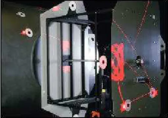
The demonstration setup utilized the 3A-Z1 install task simulation in the Neptec Vision System Certification Lab (VSCL), shown in Figure 9. This simulation consisted of half-scale models of the Unity and Z1 truss models with Inconel targets applied in flight locations and closely located retro-reflective targets. The model set-up simulated an orbiter orientation with the starboard wing into the floor of the lab with the nose toward the east wall and the payload bay toward the north wall.
For demonstration purposes a good quality JVC video camera and the LCS had been set up in a location that roughly approximates the center of the payload bay on a GAS bridge in the aft section of the payload bay. This configuration demonstrated the LCS performance in a flight like task geometry; the relationship between sensor, targets and payloads is representative of on-orbit operations. The results indicated that, under the correctly chosen conditions, the agreement between the camera and LCS solution was within 6 mm (0.25") and 0.25 degrees (worst case).
Lighting Robustness Testing
To demonstrate the robustness of the LCS to adverse lighting conditions, different specific lighting configurations were used.
• Light was placed to create a sharp shadow in the vicinity of a target. By raising and lowering the light the shadow could be made to move across the face of the target such as illustrated in Figure 11.
• Shining a very directional 1000-Watt light source directly at the LCS and camera. This situation was intended to simulate the condition of the sun shining directly into the camera.
• Measurements done outside under clear sunny day.
Testing showed that when using the video camera, the SVS would not continue to generate a solution. When the same test was performed with the LCS there was no loss of solution. In [9] a more complete sensitivity analysis of the tracking system to sun interferences is presented.
Figure 11: Effect of light shadows on a target. Figure 9: The Node and Z1 modules experimental setup (1/2
scale).
Figure 10. Real-time tracking of targets on the simulated Node and Z1 modules. Two types of target are visible, Inconel B/W and retro-reflective targets. The system tracks each retro-target sequentially. In this example, one of the targets is in “search mode” (larger Lissajous pattern).
System Dynamic Range
The geometrical tracking principle uses both the 3D range and intensity information on the scanning pattern to (a) identify targets on the object or any useful geometrical feature, and (b) to discriminate the target from its background. Although it seems a-priori that intensity reflectance should be sufficient, in practice this is far from reality since target reflectivity is highly dependant on surface material, angle of incidence on the surface, specular reflections, and ambient illumination. Tracking brings very interesting and practical challenges for automated detection:
• illumination and poor contrast between the targets and/or geometrical features and their surrounding background,
• specular reflections created by metallic structures,
• defects and non-uniformity of the targeted surfaces,
• variations in the material reflectivity, surface incident angles,
• ambient intensity variations and shadows introduced by sunlight,
• occlusions.
For example, the reflected signal ratio between the white surface and its darker background may vary between 2:1 and 1.5:1 depending on the incident angle of the laser beam (10:1 for Inconel material). Other interesting dynamic signal ratios are non-uniform signal response of the “dark” background and vignetting (3:1), variations of reflectivity versus surface incident angle (4:1), specularity of non-diffusing surfaces (>20:1), ambient light and shadows (3:1), variation of target reflectivity with range (>100:1). The laser scanner must therefore exhibit an equivalent SNR of more than 104 to 105 of dynamic range, far exceeding the 256:1 ratio of conventional frame grabbers and the 20:1 of electronic shutters. With the laser technology, this is accomplished by dynamically varying the laser power and the sensitivity of the laser spot position sensor on a per target basis, and by automatic compensation of the non-linear dynamics of the scanning system. Because of the constraints of signal dynamic range (104 to 105 and Figure 11) geometrical range processing is the only truly reliable method to differentiate the target from its environment.
7. GEOMETRICAL TRACKING
To simplify the discussion, we are here assuming that most geometrical objects can be modeled using planar surfaces (or meshes). Because the laser scanner provides range information, the equation of a surface can be defined using 0=ax+by+cz+d. Target discrimination is obtained by removing measurements that do not belong to the plane of the target. Because most objects can be defined using planes, meshes, or simple geometries, best fit of surfaces (or simple geometries) is a robust method for target detection and tracking as seen in Figures 12 to 14. Although the extension of the method to other geometries such as spheres will not be presented here, it is obviously possible as seen in Figure 13.
Figure 12. Tracking using the Lissajous pattern and a planar circular target.
Figure 13. Geometrical tracking of a sphere illustrating the discrimination of similar colour/shape targets at different range.
Figure 14: Tracking of natural geometrical features.
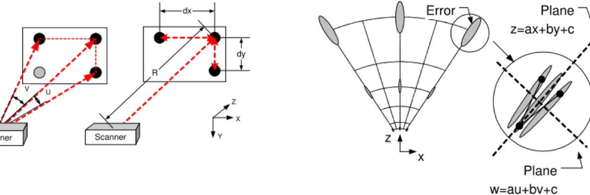
There is major drawbacks using quadratic error fitting (plane) in the XYZ coordinate system because x, y, and z are highly correlated with range R [12]. Referring to Figure 16, the distribution of the errors in the x-z plane is depicted with ellipses with varying dimensions in order to show the anisotropy and inhomogeneity of the distribution. Statistically, this will show as non-zero terms outside the diagonal of the error covariance matrix. Physically, this will be seen as non-continuous profiles as shown in Figure 16 where we can have retrograde motion in the x scanning profile. Real-time geometrical target processing and tracking in the laser scanner inverse spherical coordinate system is used. This corresponds to the angles of measurements and the inverse of the range u=x/z, v=y/z, and w=1/z [12]. Using the homogenous UVW coordinates system, the high correlation normally obtained using the three axes x-y-z in the Cartesian coordinate system relative to the object distance R, is minimized. The UVW coordinate system also eliminates the z2 dependency of range error, linearizing the error equations, and more important, eliminating the possibility of ill-conditioned systems of equations. Of primary interest is the direct relationship between the sensor raw measurements and the equation of a plane z=ax+by+c, becoming w=αu+βv+χ. Linear minimization techniques can then be efficiently used since the errors are constant for the whole volume. Furthermore, because u and v are mostly correlated with only the angles ϕ and θ, of the scanner, quadratic error minimization will never be ill conditioned, of primary importance for real-time computation. Several techniques can be used for plane extraction; the method we selected combines split and merge and outlier removal (robust fitting).
Figures 10 to 12 demonstrate the tracking method using the plane of the target to discriminate the target from the surrounding environment and ambient light. The intensity gradient of the target is used to discriminate the target itself. Figure 13 shows geometrical tracking. If we compare the method with a 2D video camera, the background target and the sphere will be identical (same color) and impossible to differentiate using conventional video methods. Finally, Figure 14, shows an extension of the technique tracking natural object features.
8. OBJECT POSE EVALUATION
Object pose evaluation is a complex subject by itself and an in depth analysis is beyond the scope of this paper. We will rather provide here a qualitative analysis of the method from a mathematical point of view based on similar concepts. Assuming a set of known coordinates (xo,yo,zo) on a rigid object, the expected location of these targets in the laser
scanner 3D space (x),y),z)) is given using Xˆ =M⋅Xowhere M is a 4x4 rigid transformation matrix (|M|=1) that maps the object target coordinates Xo=
[
xo yo zo 1]
Tin the laser scanner space[
]
T
z y x
Xˆ = ˆ ˆ ˆ 1 . The matrix M has 6 unknowns, 3 translations and 3 rotations (yaw-pitch-roll). Object pose estimation consists of evaluating the
transformation matrix that will minimize a set of error equations. The most commonly used method minimizes the quadratic error between the expected position computed from the previous equation and the laser scanner measurements
[
]
Tz y
x 1
=
X . Different techniques are available to minimize this set of equations such as based on least-squares adjustment, and quaternion. However, for medium to long range, the error vector Å=X−Xˆ will be highly dependent on the range measurement ∆E≈R2∆p. Using the camera pinhole model and photogrammetry methods, pose
estimation requires the minimization of the error vector Å=U−Uˆ of the projected vector U=[u v 1]T and the dependence of the error vector E on range R is minimized compared to the previous approach.
U V Scanner Scanner R dx dy X Y Z z x Error Plane z=ax+by+c Plane w=au+bv+c
Figure 15: Object pose calculation based on 3D range data (left) and photogrammetry techniques (right).
Figure 16. Dependencies of x-y-z measurement errors with radial range R (equation 4). Note the retrograde motion of the x-axis and the plane fits.
Accuracy of the photogrammetric method should then be much better than direct range data minimization for medium to long range R. Figure 15 illustrates the two object pose evaluation methods. Obviously, to obtain the desired pose accuracy, the data must first be calibrated using the complete laser scanner model. Because we are only calibrating the location of the centroid of the target, real-time constraints are reduced.
In order to compare the two methods, the targets on the structure shown in Figure 17 were divided in three groups and the targets acquired over a period of twelve hours. Standard deviation of the pointing stability for the targets was 40
µrad. Figure 18 shows the results of the object pose model (simulation) using the previous methods for a 1 m × 1 m array and for the targets of Figure 17. Increased stability/resolution using the photogrammetric model UV, compared to XYZ data is important. At the time of writing, work for the calibration of the laser scanner are still in progress and the absolute accuracy experimental results of the method were not available.
There are several key factors that must be considered when comparing the stability of the pose from the model data and these experimental results, the most important being the distribution of the target, the number, and their sustained angle (size). For the UVW method, the distribution of the targets on the structures of Figure 17 was definitely an advantage, providing a large triangulation base (Figure 15). The model used a regular target array of 1 m × 1 m, while the experimental data used targets distributed within the whole FOV of the laser scanner. This gain is important at longer range for the UV method and almost negligible for the XYZ method. In [13] the B/W targets were bigger than the targets used here and pointing accuracy has also been improved. From both the simulated model and experimental data, an increase in accuracy using resection methods is important. This also clearly demonstrates the advantages of the combined methods, i.e. the use of a laser range scanner as a projective camera.
9. CONCLUSION
This paper has presented some of the research performed at the National Research Council of Canada toward the 3D acquisition of non-cooperative environments. Because most of current 3D acquisition systems still require static scenes and supervised operations, the dynamics of the 3D system is becoming very important for dynamically uncontrolled
environments. Dynamic geometrical tracking and space applications provided an initial impetus to study this objective. Because the dynamics of the acquisition process is an extremely complex question, this work has progressively solved several key questions:
• the acquisition of dense 3D images and the integration of multiple views for the creation of complex 3D objects to study the basic problems of acquisition and small volume calibration;
• the demonstration of large volume cooperative target tracking and immunity to sun illumination to analyse the problems of ambient light interferences;
• the understanding of the scanner and the acquisition process dynamics;
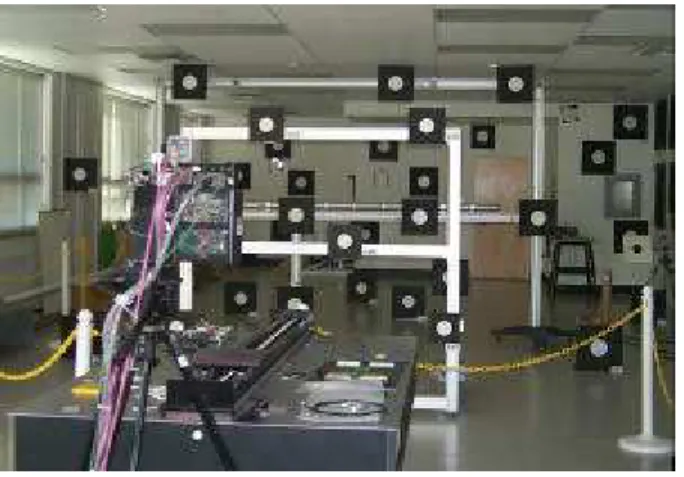
Figure 17. Experimental setup used to verify the accuracy of the tracking system. The blinds were shut to prevent saturation in this photograph.
Figure 18: Model simulation and experimental results for analysis of the stability of the pose.
0.1 1 10 100 0 5 10 15 20 Range (m) Z Stability Error (mm)
XYZ - Simulation XYZ - Experimental UV - Simulation UV - Experimental
• a first demonstration of geometrical object features/target tracking and larger volume calibration
• the evaluation of the dynamics of object/scanner relative position (moving objects).
Future work should demonstrate the tracking of complex 3D geometrical features, the integration of simultaneous imaging and tracking (moving object/camera), and fully automated acquisition.
10. ACKNOWLEDGMENTS
This work is part of a more ambitious collaborative project between Neptec Design Group, the NRC and CSA, of developing flight-ready space qualified version of this laser scanner system. The authors would like to acknowledge their precious collaboration.
11. REFERENCES
1. F. Blais, M. Rioux, and J.-A. Beraldin,”Practical Considerations for a Design of a High Precision 3-D Laser Scanner System,” Proc. Soc. Photo-Opt. Instrum. Eng. 959, 225-246 (1988).
2. J.-A. Beraldin and al., “Real world modeling through high resolution digital 3D imaging of objects and structures”, ISPRS Journal of Photogrammetry and Remote Sensing, 55 (2000), 230-250.
3. www.shapegrabber.com
4. F. Blais, M. Rioux, and S.G. MacLean, “Intelligent, Variable Resolution Laser Scanner for the Space Vision System,” in Acquisition, Tracking, and Pointing V, Proc. Soc. Photo-Opt. Instrum. Eng., 1482, 473-479 (1991).
5. F.Blais, J.-A. Beraldin, L.Cournoyer, I. Christie, R. Serafini, K. Mason, S. McCarthy, C. Goodall., “Integration of a Tracking Laser Range Camera with the Photogrammetry based Space Vision System”, Acquisition, Tracking, and Pointing XIV, Proceedings of SPIE’s Aerosense 2000 Vol. 4025, p. 219-228, (2000), Orlando, FL.
6. S.G. MacLean, M. Rioux, F. Blais, J. Grodski, P. Milgram, H.F.L. Pinkney, and B.A. Aikenhead, “Vision System Development in a Space Simulation Laboratory,”in Close-Range Photogrammetry Meets Machine Vision, Proc. Soc. Photo-Opt. Instrum. Eng., 1394, 8-15 (1990).
7. S.G. MacLean, and H.F.L. Pinkney, “Machine Vision in Space,” Canadian Aeronautics and Space Journal, 39(2), 63-77 (1993).
8. http://www.neptec.com
9. F. Blais, J.-A. Beraldin, S. El-Hakim., “Range Error Analysis of an Integrated Time-of-Flight, Triangulation, and Photogrammetric 3D Laser Scanning System,” Laser Radar Technology and Applications V, Proceedings of SPIE’s Aerosense 2000 Vol. 4035, p. 236-247, (2000), Orlando, FL.
10. Beraldin, J.A., Rioux, M., Blais, F., Cournoyer, L., and Domey, J. Registered intensity and range imaging at 10 mega-samples per second. Opt. Eng. 31(1): 88-94; 1992.
11. Beraldin, J.-A., Blais, F., Rioux, M., Cournoyer, L., Laurin, D., and MacLean, S.G., “Eye-safe digital 3D sensing for space applications”. Opt. Eng. 39(1): 196-211; Jan. 2000.
12. F. Blais, J.-A.Beraldin, S. F. El-Hakim, L. Cournoyer, "Real-time Geometrical Tracking and Pose Estimation using Laser Triangulation and Photogrammetry", 3DIM2001,Third International Conference on 3D Digital Imaging and Modeling, May 28 - June 1, 2001, Québec City, Canada
13. Blais, F., Beraldin, J.-A., and El-Hakim, S.F. Range error analysis of an integrated time-of-flight, triangulation, and photogrammetry 3D laser scanning system. SPIE Proceedings, AeroSense, Orlando, FL. April 24-28, 2000. Volume 4035.