READ THESE TERMS AND CONDITIONS CAREFULLY BEFORE USING THIS WEBSITE. https://nrc-publications.canada.ca/eng/copyright
Vous avez des questions? Nous pouvons vous aider. Pour communiquer directement avec un auteur, consultez la
première page de la revue dans laquelle son article a été publié afin de trouver ses coordonnées. Si vous n’arrivez pas à les repérer, communiquez avec nous à [email protected].
Questions? Contact the NRC Publications Archive team at
[email protected]. If you wish to email the authors directly, please see the first page of the publication for their contact information.
NRC Publications Archive
Archives des publications du CNRC
This publication could be one of several versions: author’s original, accepted manuscript or the publisher’s version. / La version de cette publication peut être l’une des suivantes : la version prépublication de l’auteur, la version acceptée du manuscrit ou la version de l’éditeur.
Access and use of this website and the material on it are subject to the Terms and Conditions set forth at
A Framework to Support Structural Reuse in Simulation Environments.
Tanir, O.
https://publications-cnrc.canada.ca/fra/droits
L’accès à ce site Web et l’utilisation de son contenu sont assujettis aux conditions présentées dans le site LISEZ CES CONDITIONS ATTENTIVEMENT AVANT D’UTILISER CE SITE WEB.
NRC Publications Record / Notice d'Archives des publications de CNRC:
https://nrc-publications.canada.ca/eng/view/object/?id=838eeab0-4285-4286-83c4-7b9cf0f9089f https://publications-cnrc.canada.ca/fra/voir/objet/?id=838eeab0-4285-4286-83c4-7b9cf0f9089f
National Research Council Canada Institute for Information Technology Conseil national de recherches Canada Institut de technologie de l’information
A framework to support structural reuse
in simulation environments.
*
Tanir, O., Erdogmus, H.
June 1997
* published in: Proceedings of the 1997 European Simulation Multiconference (ESM'97), Istanbul, Turkey. June 1-4, 1997. pp. 25-33. NRC 41545.
Copyright 1997 by
National Research Council of Canada
Permission is granted to quote short excerpts and to reproduce figures and tables from this report, provided that the source of such material is fully acknowledged.
A FRAMEWORK TO SUPPORT STRUCTURAL REUSE IN SIMULATION
ENVIRONMENTS
Oryal Tanir
Bell Canada, Quality Engineering & Research
265 Roland Therrien Blvd., Longueuil, Québec, J4N 1C5, Canada [email protected]
Hakan Erdogmus
National Research Council of Canada, Institute for Information Technology - Software Engineering Montreal Road, Bldg. M-50, Ottawa, Ontario, K1A OR6, Canada
KEYWORDS
Structure, reuse, model, environment, design.
ABSTRACT
In the design of computer-based systems, simulation tools employed during various stages of the design cycle can provide significant insight into the behavior of the proposed design. Unfortunately the knowledge gained through the course of a simulation exercise is typically lost and inaccessible to other designs. One promising solution to this is the utilization of development environments that can support libraries of models at high levels of abstraction — more suitable for reuse. One such environment is the Design Analysis and Synthesis
Environment (DASE) based on the Design Specification Language, or DSL. DASE allows
designers to model, experiment with, and reuse model components in other designs. Whereas
component reuse has been studied extensively and
widely supported in environments such as DASE, reuse of a different form — structural reuse — is still relatively poorly understood. The Extended
Style Notation (ESN) establishes a basis for
describing the abstract structure of systems at a high level — thus facilitating structural reuse. This paper presents a framework — a marriage of ESN and DSL — to create a rapid prototyping and simulation environment supporting both structural and component reuse.
INTRODUCTION
Component reuse is possible when an artifact recurring in system descriptions can be isolated and
encapsulated as a unit of abstraction. Then the artifact is conveniently incarnated on demand by a simple reference to the corresponding unit of abstraction. With structural reuse, the objects of reuse are not the individual artifacts that make up a system description, but rather the “contexts” in which these artifacts are embedded. Thus structural reuse is based on the identification and isolation of organizational patterns recurring across system descriptions, thereby allowing these patterns to be taken advantage of over and over again. In this context, an organizational pattern is expressed in terms of configurations of abstract components which serve as place holders for real, or concrete, components. Such patterns are often parameterized, making them generic — and hence more amenable to reuse.
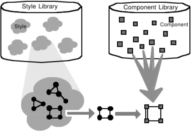
Reusable artifacts are often grouped into libraries. When a component is reused, it is instantiated once and this instance is final. One can also envision reusable libraries of organizational patterns. When a pattern is reused from such a library, first it must be retrieved and instantiated in the same way a component is retrieved and instantiated. The result is a fixed pattern, but this does not constitute the required final artifact since it still is expressed in terms of abstract components for which concrete counterparts must be substituted. Therefore, a second level of instantiation is necessary. In the software architecture literature, an organizational pattern is often referred to as a style and the kind of reuse described above is referred to as style-based reuse (Shaw and Garlan 1992, Monroe and Garlan 1996). This is illustrated in Fig. 1.
To identify and formally specify an organizational pattern may be a substantial undertaking, in which case the process would be worth the effort if either
2
the underlying complexity is nontrivial, or there is a high degree of internal replication (many identicalcomponents), or the pattern can be reused
sufficiently many times. Today, a large number of concurrent and distributed systems possess a degree of organizational complexity which makes structural reuse increasingly important.
The Concept of Architecture
The term architecture is overused. Since its definition is specific and the notion is central to the paper, it is worthwhile to review the usage of the term in the relevant literature.
Although there is no widely accepted definition of an architecture and opinions are abound as to what kind of information an architectural specification is supposed to convey, it is generally agreed that at the architectural level of abstraction, the key issue is the gross decomposition of a system into components and relationships among those components (Garlan and Shaw 1993, GARLAN ET AL. 1994, Shaw et al. 1995). Different definitions arise from placing the focus on different aspects of system design at the architectural level. In (Tanir 1997), this level falls somewhere between the conceptual and algorithmic levels of design, where a system is described as a network of communicating components.
In the software engineering literature, several different definitions can be found. In this framework, the vocabulary invariably refers to the notions of
component, connection, and configuration, where
components represent computational entities,
connections represent relationships or interactions
between these entities, and configurations represent the overall organization of a system in terms of the constituent components and connections. According to (SCHWANKE ET AL. 1989), architecture
specifies structure alone as the permitted set of connections among components. This purely structure-oriented view is also adopted in (Dean and Cordy 1995). In VHDL (Lipsett et al. 1990), architecture (and the corresponding language construct) also refers exclusively to structure. In the architecture description language RAPIDE (Luckham and Vera 1995), architecture is defined as a “plan of a distributed object system showing what types of modules are components of the system, how many components of each type are there, and how its components interact.” Here an architectural plan, besides serving as a template for guiding the construction of a system, is also used to “prototype its behavior before effort is put into building the components,” and this implies some degree of behavioral modeling at the architectural level (Luckman et al. 1995, Luckham and Vera 1995). Perry and Wolf’s definition (Perry and Wolf 1992) goes further. They consider architecture as composed of — in addition to components and connections — constraints and a rationale which together may address not only topological and functional (behavioral) properties (such as data and control flows, communication protocols, and synchronization), but also extra-functional aspects (such as performance, reliability, security, and
modifiability). Garlan and Shaw (Shaw and Garlan
1995) also adopt a similar extended definition. In this view, Shaw et al. state in (Shaw et al. 1995) that “in addition to specifying the structure and topology of the system, the architecture shows the
intended correspondence between the system
requirements and elements of the constructed system. It can additionally address system-level properties such as capacity, throughput, consistency, and component compatibility.” Finally, according to Perry and Wolf (Perry and Wolf 1992) and also Clements (Clements 1994), architecture is not merely a one-dimensional view of the gross organization of a system, but is a collection of one or more useful complementary views that are consistent with each other.
STRUCTURAL REUSE
FRAMEWORK
A compelling motive for structural reuse is that at some high level of abstraction, it is desirable to concentrate on the gross structure of a system. At this level, component functionality is secondary, with primary emphasis on the organization of components with respect to each other. In this
Style Library Component Library
Style Component
3
respect, one is interested only in whether or not a connectivity relation exists between any given two components. This very high-level of abstraction will be referred to as the topological level.The next level is the so-called architectural level, where although more detail can be added, components are still not assigned particular functionalities. The line between topological and architectural levels is ordinarily blurry. However, distinguishing between the two can be beneficial since complexity can be reduced with the subdivision of the structure into two levels, and reuse facilitated with the higher level of abstraction. Essentially, the more general a structural specification is, the more reusable it becomes.
In going from a topological to an architectural specification, component interfaces and connectivity relations may be refined. Such refinement basically involves mapping abstract components to concrete components with multi-port interfaces, and also mapping connectivity relations between abstract components to bindings between the interface ports
of the participating concrete components.
The system level is where each concrete component is assigned a functionality in terms of a behavioral description. This involves mapping the architectural specification to an executable model where bindings may be implemented by standard communication protocols or by the underlying communication regime of the executable model. Note that the
system level encompasses the architectural level in the same manner the architectural level encompasses the topological level.
We propose a framework for style-based structural reuse which supports the three levels of abstraction described above. Activities at the topological and architectural levels are supported by ESN. System level support is realized by DSL. The proposed framework and the related methodology are summarized in Fig. 2.
ESN Basics
ESN is a strongly typed, interpreted functional language based on the Style Calculus (Erdogmus 1996), a graph algebra with both an axiomatic and a denotational theory, and the architectural model of (Erdogmus 1995). It has special constructs for expressing topologies and classes of topologies (the
style sublanguage), refinement rules (the map
sublanguage), and architectures (the template sublanguage). In ESN, the unit of abstraction is the
definition. Functions of integers (int), booleans
(cond), names (name), styles (style), templates (temp), and maps (map) can be defined, as well as sets and vectors of integers and names. ESN also has a package facility for library support which is not discussed here.
Expressions of type style in ESN specify topologies. Formally, a topology is a finite graph consisting of typed (and named) nodes and named binary edges. A parameterized style definition (a generic style) is often thought of as specifying a topological class, which when invoked with actual parameters, is evaluated into an instance, yielding a particular topology. Expressions of type template specify architectures, and those of type map specify refinement rules. Constants of type name (which always begin by a backslash) stand for themselves, and can be indexed by an integer vector; e.g., \a, \a<1, 2>. A definition invocation must be prefixed with the type of the value returned, e.g., name a, int b[k], style S[~a, 1]. The default type is int (which is ordinarily omitted) and the symbol ~ is often used as a shorthand for the type keyword name. Strong typing allows the inference of the type of any ESN expression independent of the context.
An ESN definition is uniquely identified by its
signature which is made up of the type of the return
value, a definition identifier, and the types of the formal parameters (if any). A definition returns its signature (an object of type sig) when evaluated. We
Topological Architectural System E S N E S N DSL Abstraction Level Modeling Language VHDL Concept Language Construct Activity Simulate & synthesize Topology Refine Instantiate Translate & define behavior Process or Entity Topological Class Style Map Style Architecture Template System Module Refinement Rules System
4
do not discuss signatures further here. It is possible to specify pre- and post-conditions for a definition. These indicate the constraints that must be satisfied, respectively, before and after the body of the definition is evaluated.DSL Overview
DSL is a specification language which provides the necessary representation mechanisms at the system level of design. It is employed within DASE (Tanir 1994, Tanir 1997), a rapid prototyping and synthesis tool that was developed at McGill University and Bell Canada. DSL is based on Prolog in which DASE is implemented. This section will summarize some of the basic concepts of the language.
The basic construct in DSL is the module. Modules are the primitive building blocks of a system. A module has a name, a set of possible behaviors, and a set of resources. A module is defined as follows: module(module_name, [
behavior1, ...
behaviorN ]).
Each behavior is consists of a guard and a sequence of actions. If the guard is satisfied, the associated actions are executed in the given order. The guard is usually a predicate which holds true upon the reception of a communication message from another module. An action can initiate communication with other modules, modify or query the local resources of the module, or suspend the execution of the module for a specified time period.
Modules can possess their own unique behavior or can inherit the behavior of other modules. Resources store local data associated with a module. Note that resources are not employed in the simple example provided below.
Inter-module communication is realized using the send construct (action) whose general form is:
send(destination, port, message)
where message is the message to be sent; port specifies an output port; and destination specifies the destination module. When the destination field is blank (“_”), the message is sent to the first module connected to port capable of interpreting the message. If a port is not specified, one will be synthesized during simulation.
Within DASE, the DSL simulator creates the data structures necessary for communication, and takes care of internal queuing of incoming and the scheduling of outgoing messages.
DSL permits hierarchical specifications through the composition of modules into higher order (ho-) modules. Connections between modules within a ho-module are specified using path statements. A path statement binds a port of one module to a port of another module. It serves as a virtual communication channel. For example,
path(modX, modY, [portX, portY])
binds portX of modX to portY of module modY. Note that since ports are not typed, any message can be sent from or received at any port. A (primitive) module’s behavior only refers to output ports, not input ports. Thus, inside a (primitive) module, it is not known at which port a particular incoming message is going to be received. This is determined at execution time by the simulator using the path statements associated with ho-modules. Path statements are not mandatory; the DSL simulator is able to synthesize such bindings between ports at execution time.
DSL also has a special library mechanism to support component reuse and design space exploration. But the discussion of this topic is beyond the scope of this paper.
Translation from ESN to DSL
An ESN template specifies the architecture of a distributed system in terms of an interface (a collection of ports), a set of components (expressed as instances of other templates), and a set of
bindings between the interface ports of its
components. A primitive template does not possess an internal structure, and thus simply consists of an interface. At the system level, each ESN primitive template is implemented by a corresponding DSL module. Which DSL module to use and how to instantiate it is specified by a with clause in the translations part of a template. The translations part is evaluated by a language-specific translator when an instance of the template is exported to a system-level language. As an example, consider the following primitive template:
5
...translations
with DSL use "modX(1, %(N))" where \p is "dsl_port_p", rep k from 0 .. N-1 in \q<k> is "dsl_port_q(%(k))", end rep end with end def;
Here, the ESN-to-DSL translator is instructed to use a module named modX for every instance of the above template. The module must have two parameters, and each time the template is instantiated with parameter N, modX is instantiated with parameters 1 and N. Thus the value of the second parameter of modX is bound to the value of the template's parameter N. In the where clause, the port correspondences are defined. In the above example, the port named \p of the template is mapped to the port dsl_port_p of the module modX. Similarly, for k from 0 to N-1, the template's \q<k> port is
mapped to the module's port dsl_port_q(k) (a
parameterized port).
EXAMPLE: AN ATM SWITCH
FABRIC
Let us illustrate the methodology through a small example. Here we specify the fabric of an Asynchronous Transfer Mode (ATM) switch (Awdeh
and Mohftah 1995). The architectural model given
here is that of the fabric component of a Banyan switch.
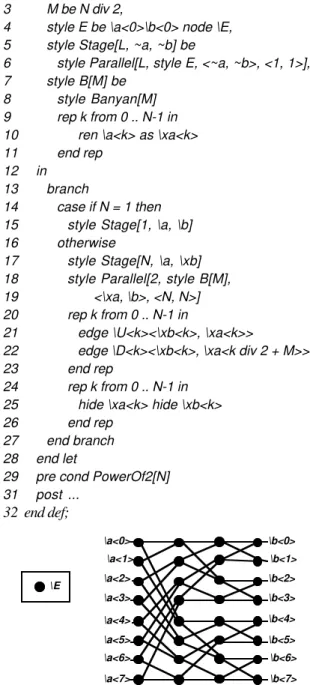
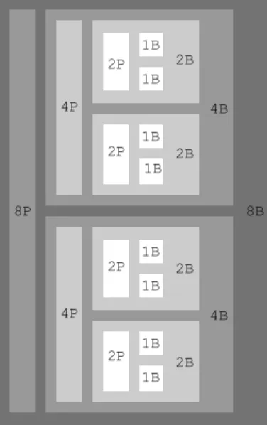
First, the topology of a Banyan network is specified. An N x N Banyan network, where N is a positive
power of 2, consists of N*N switch elements,
represented by nodes of type \E. 2*N of these nodes are external (visible) nodes. There are two kinds of external nodes, the first N of which are named \a<0> to \a<N-1> and designated as entry nodes, and the remaining N of which are named \b<0> to \b<N-1> and designated as exit nodes. Such a network can be constructed recursively using two N/2 x N/2 Banyan networks (see Fig. 3) organized in parallel and an additional entry stage of N parallel elements (see Fig. 4. For the resulting topology.)
Following this recursive construction, the topology of a Banyan network for an arbitrary N can be specified by the following generic style:
1 def style Banyan[N] is
2 let
3 M be N div 2,
4 style E be \a<0>\b<0> node \E, 5 style Stage[L, ~a, ~b] be
6 style Parallel[L, style E, <~a, ~b>, <1, 1>], 7 style B[M] be
8 style Banyan[M]
9 rep k from 0 .. N-1 in 10 ren \a<k> as \xa<k>
11 end rep
12 in
13 branch
14 case if N = 1 then 15 style Stage[1, \a, \b]
16 otherwise
17 style Stage[N, \a, \xb] 18 style Parallel[2, style B[M], 19 <\xa, \b>, <N, N>] 20 rep k from 0 .. N-1 in
21 edge \U<k><\xb<k>, \xa<k>>
22 edge \D<k><\xb<k>, \xa<k div 2 + M>>
23 end rep
24 rep k from 0 .. N-1 in 25 hide \xa<k> hide \xb<k>
26 end rep
27 end branch 28 end let
29 pre cond PowerOf2[N] 31 post ... 32 end def; \a<1> \a<0> \a<2> \a<3> \a<4> \a<5> \a<6> \a<7> \b<1> \b<0> \b<2> \b<3> \b<4> \b<5> \b<6> \b<7> \E
6
We do not discuss the individual style constructs in detail here. The construct node applied to a name expression creates a single node of the type specified by the name expression (line 4). The nodes of a style can be named through prefixing a style expression by a name expression (line 4). The named nodes become external and can subsequently be used in an edge. By concatenating two style expressions, larger styles are obtained (lines 17–19). The postfixsemantic renaming construct ren is used to rename
the nodes of a given style expression (line 10). The postfix construct edge introduces named edges between nodes; the nodes are identified by a name pair (lines 21–22). The postfix construct hide is used to hide a specified external (node) name of a style (line 25). Note that, in addition to these constructs, the above definition takes advantage of a generic Parallel style whose definition is omitted here. The next step involves the mapping of the topology
defined by the style Banyan to a concrete
architecture. To do this, we need a primitive template to represent the switch element component of a Banyan switch:
def temp BE is spec temp
interface \x<0>, \x<1>, \y<0>, \y<1> end spec
translations
with DSL use "binary_switch_elmt" where \x<0> is "x(0)", \x<1> is "x(1)",
\y<0> is "y(0)", \y<1> is "y(1)" end with
end def;
Thus the switch element component has four interface ports, namely \x<0>, \x<1>, \y<0>, and \y<1>. Now we can define a map which specifies the refinement rules for the Banyan style so that a composite template can be synthesized from it. The respective map can be expressed as:
1 def map Banyan_to_BANYAN[M] is
2 let
3 ~x[k] be if cond Even[k] then \x<0> 4 else \x<1> end if 5 in 6 spec map 7 interface 8 rep k from 0 .. M-1 in 9 \a<k> to \x<0> as \i<2*k>, 10 \a<k> to \x<1> as \i<2*k+1>, 11 \b<k> to \y<0> as \o<2*k>, 12 \b<k> to \y<1> as \o<2*k+1> 13 end rep 14 components 15 \E to `temp BE’ 16 bindings 17 rep k from 0 .. M-1 in 18 \U<k> to <\y<0>, ~x[k]>, 19 \D<k> to <\y<1>, ~x[k]> 20 end rep 21 end map 22 end let
23 pre cond Powerof2[M] 24 end def;
Line 15 states that each \E-node must be mapped into an instance of the template BE. Refinement of the edges (connections) are specified by the bindings part (lines 16–20). The rules regarding the interface ports of the synthesized template and the bindings associated with these interface ports are specified in the interface part (lines 7–13). For example, line 9 states that for each external (visible) node having name \a<k>, there must be a corresponding component with an interface port \x<0>, and that this interface port is to be bound to the interface port \i<2*k> of the synthesized template. Finally, the switch fabric is defined as the synthesized template SF by applying the above map to the Banyan style: def temp SF[M] is
extend
let L be M div 2 in
apply map Banyan_to_BANYAN[L] to style Banyan[L] end let with interface \r end extend 1B 1B 1B 1B 1B 1B 1B 1B 2B 2B 2B 2B 4B 4B 8B 2P 2P 2P 2P 4P 4P 8P
Fig. 3 Recursive construction of a 8 x 8 Banyan network, where nB represents an n x n Banyan and nP represents an n x 1 stage of parallel elements.
7
pre M > 0post ... translations
with DSL use "generic_fabric(%(M))" where rep k from 0 .. M-1 in \i<k> is "cell_in%(k))", \o<k> is "cell_out%(k))" end rep, \r is "synch_in" end with end def;
Note that the architectural model of the switch fabric is more detailed than its topological model because a network element node of the Banyan switch is refined into a (binary) switch element component with four interface ports.
The interface port \r is added (by the extend construct) in case the switching fabric must send a synchronization message to an external component. Whether this is necessary or not will be decided at the system level. Therefore, in the architectural specification, this port is not bound to any internal port within the switch fabric. The necessary internal bindings and the missing ports of the switch components can be synthesized by DASE if the corresponding behaviors of the switch components require it. To generate the architecture of a 16 x 16 Banyan fabric with input ports \i<k>, output ports \o<k>, and a synchronization port \r, we instantiate the above template as follows:
temp SF[16];
When this expression is evaluated by the ESN interpreter, the instance illustrated in Fig. 5 is generated.
The translation rules of the primitive template BE states that in a DSL model, this template will be implemented by the DSL module binary_switch_elmnt, which may be defined as follows:
module(binary_switch_elmnt, [ (atm_cell(VPI, VCI, D, [Bit | Rest])
:-delay(BE_delay),
send(_, y(Bit), atm_cell(VPI, VCI, D, Rest))) ]). The module binary_switch_elmnt accepts ATM cells at an unspecified input port, stores them for a fixed amount of time, and routes them to one of its two output ports. A new cell is admitted by the atm_cell message whose last parameter specifies the output
port address of the switch to which the cell is destined. Upon receiving an atm_cell message, the module removes the most significant bit of this address, and uses this bit to route the cell either to its y(0) or y(1) port.
The translation rules of the template SF instructs the ESN-to-DSL translator to synthesize a ho-module generic_fabric for each instance of this template. If the definition of the module binary_switch_elmnt is stored in a directory atmSwitch, then the ESN-to-DSL translator can be invoked by an export statement such as
export `temp SF[16]’ to results:DSL using atmSwitch;
which generates automatically a DSL ho-module description and the associated path statements for the fabric component of a 16 x 16 Banyan switch, and stores the resulting description in a file named results. The generated ho-module generic_fabric is composed of several instances of the module binary_switch_elmnt.
CONCLUSIONS
This paper presented an integrated framework supporting both structural and component-based reuse for rapid prototyping and simulation of distributed computer-based systems. The idea of combining ESN and DSL to support style-based reuse in a rapid prototyping and simulation tool is novel. Work is underway to implement an ESN interpreter and interface it with DASE using an ESN-to-DSL translator. \x<1> \x<0> \y<1> \y<0> BE \o<1> \o<0> \o<2> \o<3> \o<4> \o<5> \o<6> \o<7> \o<8> \o<9> \o<10> \o<12> \o<11> \o<14> \o<13> \o<15> \i<1> \i<0> \i<2> \i<3> \i<4> \i<5> \i<6> \i<7> \i<8> \i<9> \i<10> \i<11> \i<14> \i<15> \r
8
REFERENCES
R.Y. Awdeh and H.T. Mohftah. 1995. Survey of ATM switch architectures. Computer Networks and ISDN Systems, 27:1567–1613, 1995.
P.C. Clements. 1994. From domain models to architectures. In Proc. Workshop on Architecture, USC Center for Software Engineering, Los Angeles, 1994.
T.R. Dean and J.R. Cordy. 1995. A syntactic theory of software architecture. IEEE Transactions Software Engineering, 21(4):303–313, April 1995.
H. Erdogmus. 1995A Formal Framework for Software Architectures. Technical Report ERB-1047, National Research Council of Canada, Institute for Information Technology, Ottawa, Canada. December 1995.
H. Erdogmus. 1996. From Configurations to Styles: An Algebraic Theory. Technical Report ERB-1049. National Research Council of Canada, Institute for Information Technology, Ottawa, Canada. June 1996.
D. Garlan, R. Allen, and J. Ockerbloom. 1994. Exploiting style in architectural design environments. In Proc. of SIGSOFT’94, Second International ACM SIGSOFT Symposium on Foundations of Software Engineering, December 1994.
D. Garlan and M. Shaw. 1993. An introduction to software architecture. In Advances in Software Engineering and Knowledge Engineering, vol. 1, World Scientific Publishing, 1993.
R. Lipsett, C. Schaefer, and C. Ussery. 1990.
VHDL: Hardware Description and Design. Kluwer, 1990.
D.C. Luckham and J. Vera. 1995. An event-based architecture definition language. IEEE Transactions on Software Engineering, 21(9), September 1995.
D.C. Luckham, J. Vera, and S. Meldal. 1995. Three concepts of architecture. Technical Report, The Program Analysis and Verification Group, Computer Science Department, Stanford University, July 1995.
R.T. Monroe and D. Garlan. 1996. Style-based reuse for software architectures. In Proc. 1996 International Conf. on Software Reuse, 1996. D.E. Perry and A.L. Wolf. 1992. Foundations for
the study of software architecture. Software Engineering Notes, 17(4), October 1992.
R.W. Schwanke, R.Z. Altucher, and M.A. Platoff. 1989. Discovering, visualizing, and controlling software structure. In ACM SIGSOFT Notes, 14(3):147-150, Proc. 5th International Workshop on Software Specification and Design, May 1989. M. Shaw and D. Garlan. 1992. Characteristics of
higher-level languages for software architecture. Report CMU-CS-94-210, Carnegie Melon University, School of Computer Science, December 1992.
M. Shaw and D. Garlan. 1995.Formulations and formalisms in software architecture. In Lecture Notes in Computer Science, vol. 1000, Springer-Verlag, 1995.
M. Shaw et al. 1995. Abstractions for software architecture and tools to support them. IEEE Transactions on Software Engineering, 21(6), April 1995.
O. Tanir. 1997. Specification Driven Architectural Modeling Environment for Telecommunications Systems Synthesis. PhD Thesis. Department of Electrical Engineering, McGill University, Montreal, Canada. October 1994.
O. Tanir. 1997. Modeling Complex Computer and Communication Systems: A Domain-Oriented Design Framework. McGraw Hill. 1996.
![Fig. 5 The template temp SF[16]](https://thumb-eu.123doks.com/thumbv2/123doknet/14221011.483699/9.918.497.833.802.1042/fig-the-template-temp-sf.webp)
