CANISTER DESIGN FOR DEEP BOREHOLE DISPOSAL OF NUCLEAR WASTE
By
CHRISTOPHER IAN HOAG
B.S. Naval Architecture, United States Naval Academy, 1998 Submitted to the
DEPARTMENT OF NUCLEAR SCIENCE AND ENGINEERING For the Degree of
MASTER OF SCIENCE IN NUCLEAR SCIENCE AND ENGINEERING At the
MASSACHUSETTS INSTITUTE OF TECHNOLOGY May, 2006
0 2005 Christopher Ian Hoag. All rights reserved
The author hereby grants to MIT permission to reproduce and to distribute publicly paper and electronic copies of this thesis document in whole or in part in any medium now
known or hereafter created
Signature of Author:
Certified by:
Certified by:
Accepted by:
Department of Nuclear'dence and Engineering May 2006
Profess 6rmeritus Michael J. Driscoll Department of Nuclear Science and Engineering Thesis Supervisor
Professr Richard K. Lester 4epartment of Nuclear Science and Engineering Thesis Reader
Associate Professor Jefferey A. Coderre Department of Nuclear Science and Engineering Chairman, Committee for Graduate Students
ARCHES
CANISTER DESIGN FOR DEEP BOREHOLE DISPOSAL OF NUCLEAR WASTE
By Christopher Ian Hoag
Submitted to the Department of Nuclear Engineering on May 12th, 2006 in partial fulfillment of the requirements for the degree of Master of Science in Nuclear Science and Engineering
Abstract
The objective of this thesis was to design a canister for the disposal of spent nuclear fuel and other high-level waste in deep borehole repositories using currently available and proven oil, gas, and geothermal drilling technology. The canister is suitable for disposal of various waste forms, such as fuel assemblies and vitrified waste. The design addresses real and perceived hazards of transporting and placing high-level waste, in the form of spent reactor fuel, into a deep igneous rock environment with particular emphasis on thermal performance.
The proposed boreholes are 3 to 5 km deep, in igneous rock such as granite. The rock must be in a geologically stable area from a volcanic and tectonic standpoint, and it should have low permeability, as shown in recent data taken from a Russian deep borehole. Although deep granite should remain dry, water in flooded boreholes is expected to be reducing, but potentially corrosive to steel. However, the granite and plug are the containment barrier, not the canister itself.
The canisters use standard oil drilling casings. The inner diameter is 315.32mm in order to accommodate a PWR assembly with a width of 214mm. At five meters tall, each canister holds one PWR assembly. The canister thickness is 12.19mm, with an outer diameter of 339.7mm. A liner can extend to the bottom of the emplacement zone to aid in retrievability. The liner has an outer diameter of 406.4mm and a thickness of 9.52mm. The standard drill bit used with a liner of this size has an outer diameter of 444.5mm.
Sample calculations were performed for a two kilometer deep emplacement zone in a four kilometer deep hole for the conservative case of PWR fuel having a burnup of 60,000 MWd/kg, cooled ten years before emplacement. Tensile and buckling stresses were calculated, and found to be tolerable for a high grade of steel used in the drilling industry. In the thermal analysis, a maximum borehole wall temperature of 2400C is computed from available correlations and used to calculate a maximum canister centerline temperature of 3370C, or 3190C if the hole floods with water. Borehole repository construction costs were calculated to be on the rate of 50 $/kg spent fuel, which is competitive with Yucca Mountain construction costs. Recommendations for future work on the very deep borehole concept are suggested in the areas of thermal analysis, plugging, corrosion of the steel canisters, site selection, and repository economics.
Acknowledgements
Thank you, Professor Driscoll for your vigorous interest in this topic, countless hours, and volumes of articles and references. Great thanks are also in order for Professor Lester who introduced me to the very deep borehole concept.
This would not have been possible without the United States Navy affording me the opportunity to study at MIT, and providing funding for tuition while maintaining my standard Navy benefits.
Professor Tester and Chad Augustine shared their on-going work and valuable time to provide the most recent information on drilling costs. For this I am very grateful.
To my wife, I dedicate this work for the future of our children. Her love and support have been a great help to me throughout this time.
I am most grateful for my parents, who raised me to strive for challenging goals, and taught me to exceed even my own expectations.
I would also like to thank my office mates, Craig Gerardi, Chris Handwerk, and Sung Joong Kim for their friendship.
The staff and faculty of Nuclear Science and Engineering Department have also contributed making this work enjoyable,
Table of Contents TITLE PAGE ... 1 A B ST R A C T ... 2 A CK N OW LEDG EM ENTS ... ... 3 TA BLE O F CO NTENTS ... ... ... 4 LIST OF FIGURES ... 7 LIST O F TA BLES ... 8 1 IN TR O D U CTIO N ... 9
1.1 OBJECTIVE OF THE THESIS ... 9
1.2 OVERVIEW OF THE DEEP BOREHOLE CONCEPT... ... 9
1.3 LITERATURE REVIEW... 17
1.4 SCOPE OF THE PROBLEM ... .. ... 17
1.4.1 D isposal C anister Production ... 18
1.4.2 Transportation / Accidents ... ... 18
1.4.3 T errorist A ttack ... ... 23
1.4.4 E m placem ent Process ... 23
1.4.5 Short & Long Term Environment of the Borehole... ... 30
1.4.6 R etrievability ... ...31
1.5 A RRANGEM ENT OF THE THESIS ... 32
1.5.1 C anister R eference D esign ... 33
1.5.2 Stress A nalysis ... ...33
1.5.3 T herm al A nalysis ... 34
1.5.4 Econom ic A nalysis ... 34
2 REFERENCE DESIGN SELECTION ... 35
2.1 INTRODUCTION ... ... .. ... 35
2.2 INITIAL CONSIDERATIONS ... 35
2.2.1 Waste Forms... . ... 35
2.2.2 D esign B asis ... ... 37
2 .2 .3 D epth ... 4 1 2.2.4 R equired D iam eter ... 41
2.2.5 Canister H eight...42
2.2.6 B orehole C asing ... ... 42
2.3 SUM M A RY ... 43
3 STRESS ANALYSIS ... 45
3.1 INTRODUCTION ... 45
3.2 TENSILE STRESS ... 45
3.2.1 W aste String Casing M ass... ... ... 46
3.2.2 Mass of the Waste ... ... 47
3.2.3 Mass of the Packing Material ... 48
3.2.4 Total Mass and Tensile Stress ...49
3.3 COMPRESSIVE STRESS ... 49
3.4 THERMAL STRESS ... ... ... ... 50
3.5 S U M M A R Y ... 50
4 THERM AL ANALYSIS ... 52
4.1 INTROD UCTION ... ... 52
4.2 FUEL ASSEMBLY HOMOGENIZATION ... ... ... 52
4.3 CALCULATION OF THE CANISTER CENTERLINE TEMPERATURE ... 54
4.3.1 Heat Transfer Between the Liner and Granite ... 55
4.3.1.1 Maximum Granite Temperature ... 55
4.3.1.2 Convection and Conduction... ... 56
4.3.1.3 Thermal Radiation ... ... ... ... 58
4.3.2 Heat Transfer Through the Liner...59
4.3.3 Heat Transfer Between the Liner and Canister...60
4.3.4 Heat Transfer Through the Canister ... 60
4.3.5 Heat Transfer Through the Packing Material and Waste... ... 60
4.3.6 Temperature Profile Inside the Borehole...62
4.4 PARAMETRIC STUDY OF TEMPERATURES IN THE BOREHOLE SYSTEM ... 65
4.5 SUMMARY ... ... 69
5 ECONOMICS ... 71
5.1 INTRODUCTION ... ... ... ... ... . ... . ... 71
5.2 D AILY RIG COSTS ... .. ... ... 72
5.3 TOTAL DRILLING OPERATION COST FOR A SINGLE HOLE ... ... 72
5.4 ESTIMATION OF CURRENT COSTS FOR DRILLING... ... 73
5.5 COMPARISON TO YUCCA M OUNTAIN COSTS... ... 74
5.6 SUMMARY ... .... ... ... ... . 75
6 CONCLUSIONS ... ... 77
6.1.1 C anister R eference D esign ... 78
6.1.2 Stress A nalysis ... 79
6.1.3 Therm al A nalysis ... 79
6.1.4 Economic Analysis... ... .. 80
6.2 FUTURE WORK ... 81
6 .2 .1 T h erm al A n aly sis ... 8 1 6.2.2 Plugging ... 82
6.2.3 Corrosion of Steel Canisters ... ... .... 83
6.2.4 Site S election ... 83
6.2.5 R epository E conom ics ... 84
7 A PPE N D IC E S ... 85
7.1 APPENDIX A: REFERENCE FUEL DATA ... 85
7.2 APPENDIX B: STRESS AND THERMAL CALCULATIONS ... . ... 94
7.2.1 Thermal Calculations in Air ... 94
7.2.2 Thermal Calculations in W ater... 108
7.3 APPENDIX C: SENSITIVITY ANALYSIS OF THERMAL CALCULATIONS ... ... 113
7.4 APPENDIX D: PROPERTIES OF AIR40 . ... . . . . ... .. .... .. . . . .. .. ... . . ... ... 119
List of Figures
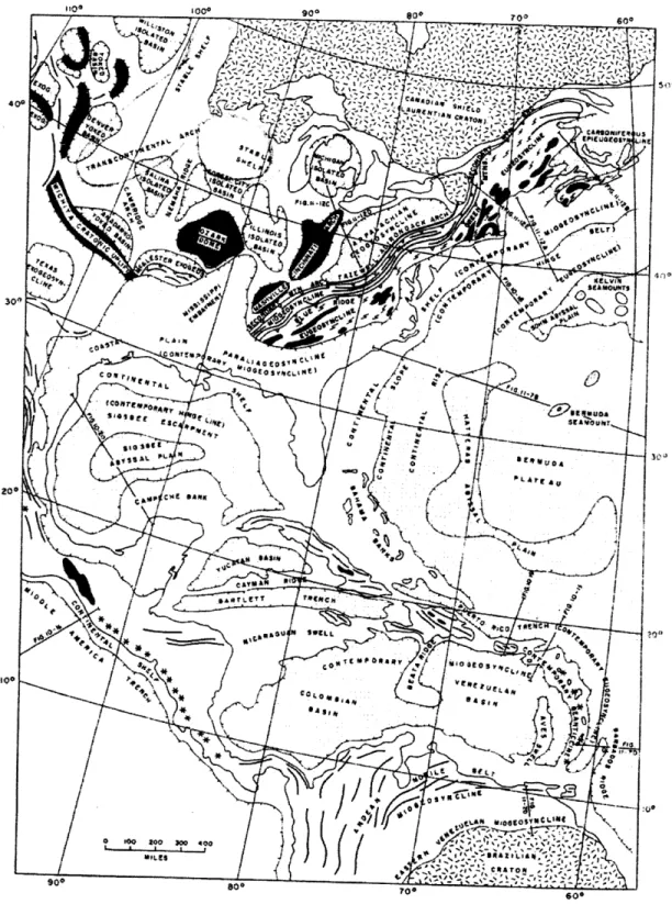
Figure 1-1 Tectonic Map of Eastern North America and Northern South America5 ... .. ... .. ... . . .. .... 13
Figure 1-2 Fault Lines in N orth A m erica ... 14
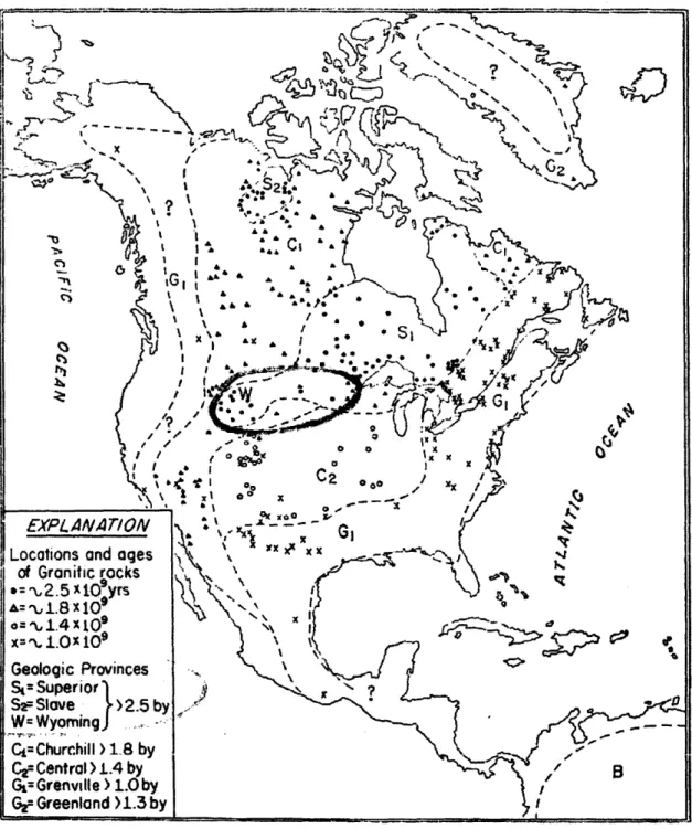
Figure 1-3 Sites of Measured Granite-Forming Events Over a Billion Years Old5 ... ... ... .. ... ... . . ... 15
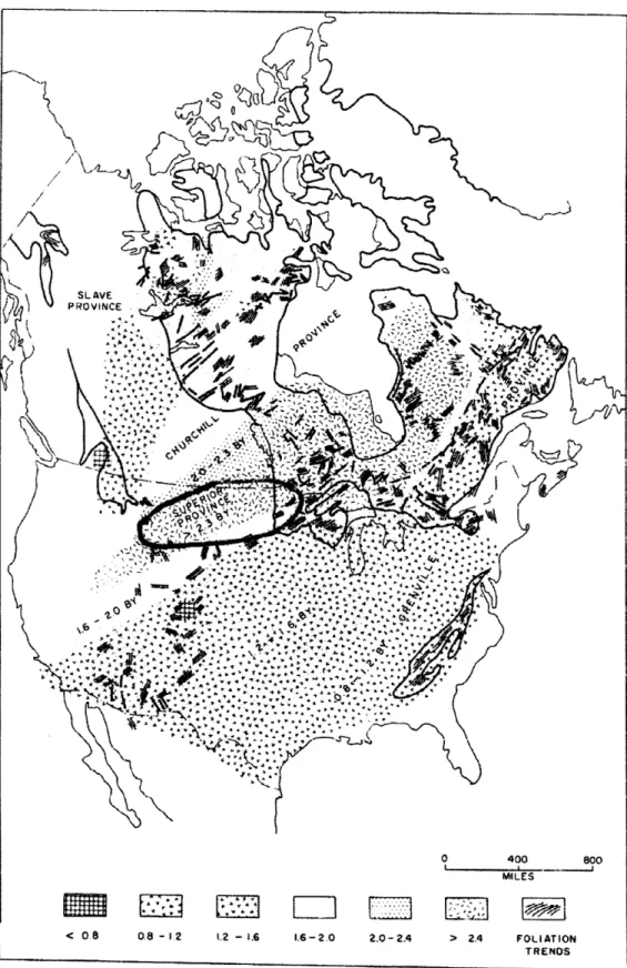
Figure 1-4 Precambrian Mineral Date Provinces of North America5. . . ... . . . . .. ... . . . 16
Figure 1-5. Typical Spent Fuel Transportation Casks...22
Figure 1-6 Layout of Em placem ent Facility6. ... .. ... ... ... .. ... ..... 25
Figure 1-7 Schematic of Waste Emplacement Rig ... ... .. . . ... ... ... ... .. ... ..26
Figure 1-8 Transfer of a Transport Cask from Truck to Rail6... .. .... ... ... .. ... . . . ... 27
Figure 1-9 Alignment of Waste Canister for Lowering into the Hole6 .... . . .. . ... .. . . . ... 28
Figure 1-10 Em placem ent Rig Basem ent ... 29
Figure 2-1 Decay Power of a 17X17 Pin Fuel Assembly ... ... 36
Figure 2-2. High Level Waste Borehole ... . ... 38
Figure 2-3. Individual Canister ... ... ... 39
Figure 2-4. TPS Casing Buttress Thread Coupling Connection to API Spec. 5CT & 5B27 .... ... ... ... .. . . . 40
Figure 4-1 Flow Diagram for Calculation of the Canister Centerline Temperature, TCL...62
Figure 4-2 Expected Temperature Profile Inside the Borehole, using the homogenized interior approximation for #16 SiC grit... ... ... ... .... ... 64
Figure 4-3 Center Line Temperature, TCL, as a function of linear power, q', and ambient granite temperature, Tamb ... ... ... ... ... ... 66
Figure 4-4 Borehole Temperature Difference between Center Line, TCL, and Borehole Wall, Tdck as a function of linear power, q', and ambient granite temperature, Tamb ... ... 67
Figure 4-5 Effect of Packing Material Conductivity on Centerline Temperature, TCL, and the "Delta T" of the Canister, A T a ... ... ... ... ... ... ... ... 68
Figure 6-1 Center Line Temperature, TCL, as a function of linear power, q', and ambient granite temperature, Tamb
List of Tables
Table 1-1. Department of Transportation Regulations for Nuclear Waste... ... 19
Table 1-2. Nuclear Regulatory Commission Regulations for Nuclear Waste... 20
Table 1-3. Environmental Protection Agency Regulations for Nuclear Waste ... .. 20
Table 1-4. R epresentative Properties of G ranite ... 30
Table 2-1 Casing Parameters For A 2km Emplacement Zone26 ... ... .. . . . .44
Table 3-1 A PI Steel Specifications ... ...46
Table 3-2 W aste Specifications... 48
Table 3-3 Packing M aterial D ata ... ...49
Table 5-1 Applicable Rig Costs and Overhead Factors ... ... 72
Table 5-2 D rilling O perations Cost A nalog per H ole ... 73
Table 5-3 Monitored Geologic Repository Costs by Phase (in Millions of 2000$) ... 75
Table 6-1 Casing Parameters For A 2km Emplacement Zone26 ... ... .. . . . ... ... .. ..78
Table 6-2 API Steel Specifications29... ... ... .. .... .. ... .. ... ... ... ... .. ..78
Table 6-3 Summary of Data for Stress Calculations ... ... 79
1 INTRODUCTION
1.1 Objective of the ThesisThe objective of this thesis is to design a canister for the disposal of spent nuclear fuel and other high-level waste in deep borehole repositories. The canister is suitable for disposal of various waste forms, such as fuel assemblies and vitrified waste. The design addresses real and perceived hazards of transporting and placing high-level waste, in the form of spent reactor fuel, into a deep igneous rock environment. The thermal performance of the design is emphasized.
To provide an option for second generation repositories at a competitive cost, the canister reference design is based on standard oil drilling technology. Calculations are conducted to assess stresses in the waste string and granite, temperatures and thermal gradients, sensitivity of thermal calculations to variables, and cost. Recommendations are made for future work.
1.2 Overview of the Deep Borehole Concept
Nuclear power has the potential to make a dramatic improvement in the earth's environment by providing large amounts of energy without producing CO2 or other harmful
gases. But one of the greatest challenges to the nuclear industry is how to dispose of the nuclear waste. Isotopes in the decay chain of uranium and plutonium, and several long lived fission products, can potentially be harmful for over a million years. The current repository design at Yucca Mountain relies principally on manmade barriers to prevent those radioisotopes from reaching water supplies, crops, and air. These manmade barriers, combined with the natural barriers of Yucca Mountain, must assure protection for over 100,000 years,
based on models having a high degree of uncertainty, including the potential for volcanic activity (Yucca Mountain is in fact in a volcanically active region). The very deep borehole concept relies on the ability of the granite to contain the waste, as evidence from a Russian deep borehole shows.1
Even if Yucca Mountain is built, it is legislatively limited to 70,000 metric tons of heavy metal (MTHM). If existing reactors operate for the extent of their licenses, there will be over 80,000 MTHM of waste, which means it is already oversubscribed.2 Furthermore, the Bush administration is pushing to expand the nuclear power industry in order to mitigate some of the effects of greenhouse gases on global warming, which will significantly increase the need for repository capacity.
Due to continuing advances in the oil and gas drilling industry, the idea of placing nuclear waste in three to five kilometer deep boreholes in igneous rock shows great promise for a final repository. Drilling companies are becoming more proficient at drilling deep (over 10km), drilling through hard rock, and drilling larger diameter holes. With more experience also comes more knowledge of the geologic environment at depth. These recent developments provide the base of information necessary to develop a preliminary canister design.
Drilling through granite is already being done for geothermal energy. The rock desired for geothermal wells is very similar to that desired for a nuclear waste repository, with one exception. Geothermal wells require fractured granite to allow water to pass from one hole to another as it is heated. In a waste repository, fractures are undesirable because they allow the migration of radionuclides. A five kilometer deep geothermal well has been drilled in Soultz, France, proving the necessary drilling capability exists.3
A deep borehole for disposal of nuclear waste will be very similar to an oil well or geothermal well, with multiple layers of casing near the surface where the ground is unstable and likely to cave in. At depth, in a solid block of granite, the borehole could be either lined or unlined. The waste canisters can be lowered by cable, or as part of a drill pipe. Once the canisters are in place, the casings near the surface can be left in place or removed, but the hole needs to be plugged, to close the direct pathway between the decaying waste and the atmosphere. The hole can be plugged immediately with a temporary plug, to ease recovery of the waste in case a better use for it is found, or in case a different disposal method is desired; however, a permanent plug should eventually be emplaced, due to the length of time during which the waste will be hazardous.
However, before drilling can start a site must be selected. An ideal site would have an unfractured granite shelf extending in depth from within one kilometer of the earth's surface down to at least four kilometers deep. A site with granite within one kilometer of the surface is not an exact requirement, but allows a four kilometer deep hole to have two kilometers of waste emplacement and one kilometer of plugging within the granite. Unfractured granite in a geologically stable zone provides a natural barrier to migration of radionuclides which is potentially far superior to any man-made barriers. Structural and Tectonic Principles by Peter C. Bradley4 contains some useful maps of the granite lithology of North America. Figure 1-1 is a tectonic map covering most of North America. Note that there is an area in the vicinity of North Dakota (930W 430N) labeled "stable shelf." Figure 1-2 is a map of fault lines in North America. Notice the lack of fault lines in North Dakota and South Dakota. Figure 1-3 shows that the granite formation in North Dakota occurred about two billion years ago. Figure 1-4 combines the data from Figure 1-2 and Figure 1-3 and labels the stable precambrian shelf
below North Dakota as "Superior Province." The various shaded areas of Figure 1-4 indicate the age of the Precambrian basement in billions of years, matching the age measurements of Figure 1-3. These maps illustrate a possible site for a very deep borehole repository. Upon more detailed inspection, sites other than North Dakota may also be found. Even though North Dakota appears suitable from a geologic standpoint, it is difficult politically to obtain approval for construction of a nuclear waste repository in any state.
400
3O"
It ,- u- I a O f L·e z x ~Jt a "" I
3
E WwO ro E10
Figure 1-2 Fault Lines in North America4
~I
3-"·.~5yl·.I-.-· i' i
£ 4 4r A ' &&r qt
Figure 1-3 Sites of Measured Granite-Forming Events Over a Billion Years Old4
EXPLANAT/ON
Figure 1-4 Precambrian Mineral Date Provinces of North America4
16
0 400 Ba0
I ._. I ...I MILES
1.3 Literature Review
In December of 1983, a thorough technical report, Very Deep Hole Systems Engineering Studies, was published by Woodward-Clyde Consultants for the Office of Nuclear Waste Isolation5. This report first described the concept, and analyzed the thermal impacts, containment and isolation, site qualification, a waste package system, the repository system, depth criteria, surface facilities, borehole design, emplacement facilities, plugs, monitoring, costs, and an engineering program plan. As thorough as this report is, it does not have a thermal analysis of the waste packages.
Over a decade ago, Weng-Sheng Kuo wrote a thesis on the feasibility of deep borehole disposal, and found the concept to be promising based on data prior to 1992.6 Advances since then have the potential to make it even more economical. For example, the ability to steer drilling and to drill multiple holes from one rig could greatly reduce drilling costs as well as reduce the number of potential pathways for radionuclides to return to the surface.
Victoria Anderson wrote a relevant thesis in 2002 on the deep borehole chemical environment.' Professors Driscoll, Lester, and others in the Nuclear Science and Engineering Department at the Massachusetts Institute of Technology (MIT), researchers at US national laboratories, and Professor Gibb8 in the UK continue to carry out research in support of the
deep borehole disposal concept.
1.4 Scope of the Problem
The following sections discuss aspects which should be considered in the design
1.4.1 Disposal Canister Production
Canister production refers to the process of placing the waste inside the canister. The canister transitions from a cool non-irradiated state to a warm irradiated state. The canister may expand and change the way the waste is seated in the canister.
Also, in the case of spent fuel assemblies the waste is very fragile, and needs a smooth and gentle transition into the canister. In a shielded area, automated or remotely operated machinery will remove the fuel assemblies from the shipping casks and place them into the canister casings. End caps will be welded to the end of the casings using automated resistance or e-beam welding to ensure a high quality weld.
Canister production should be revisited after a design and materials are chosen. Depending on the metals used there may be some aspects of fabrication which will have an effect on the performance of the canister.
1.4.2 Transportation / Accidents
Ohio State University has the following information available on its website.9 There are three federal agencies which have published regulations governing the transport of nuclear waste in the United States: the Department of Transportation (DOT), the Nuclear Regulatory
Commission (NRC), and the Environmental Protection Agency (EPA).
DOT regulations specify requirements for hazardous materials. The following are applicable DOT regulations for the shipment of radioactive waste:
Table 1-1. Department of Transportation Regulations for Nuclear Waste 49 CFR 171 General information, regulations, and definitions
Hazardous materials table, special provisions, hazardous materials 49 CFR 172 communications requirements, and emergency response information
requirements
49 CFR 173 General requirements for shipment and packaging
49 CFR 174Requirements for shipments by various means (truck, rail, ship, etc.) to 179
The NRC has established licensing requirements for radioactive waste facilities and for the packaging and shipping of radioactive waste. The NRC also sets limits on the annual radiation exposure allowed at the boundary of radioactive waste disposal facilities. NRC regulations also state that exposure to radiation should always be kept as low as reasonably possible. The following is a list of NRC regulations applicable to transport of radioactive waste to a radioactive waste disposal facility:
Table 1-2. Nuclear Regulatory Commission Regulations for Nuclear Waste
10 CFR 19 Requirements for training of radiation workers and inspections of licensed facilities
10 CFR 20 Limits on radiation doses and concentrations of radioactive materials
1 Environmental protection regulations applicable to facilities licensed by
10 CFR 51
the Nuclear Regulatory Commission
10 CFR 61 Requirements for low-level radioactive waste disposal facilities
Requirements for packaging and transportation of radioactive materials; 10 CFR 71 standards for Nuclear Regulatory Commission approval of packaging and
shipping procedures
The EPA regulations set limits on radiation doses allowed for members of the public and the amount of radioactive material introduced by nuclear facilities into the environment. The following are the EPA regulations:
Table 1-3. Environmental Protection Agency Regulations for Nuclear Waste
40 CFR 190 Limits on radiation doses to the public
40 CFR 193 Radiation protection standards for low-level radioactive waste
40 CFR 193
disposal (not yet released)
Fortunately, transportation casks for spent fuel have already been approved, built, and used as shown in Figure 1-5. The remaining question is whether to transport the assemblies prior to placing them in the permanent disposal canisters, which would allow use of the current designs for transportation casks; or, place the fuel assemblies into the final disposal canisters
prior to transport. Placing the assemblies into the disposal canisters prior to transport would require a redesign of the basket in the transportation casks, and would result in less efficient use of the limited volume in the transportation casks. In addition to the information, tables, and diagrams found on the Ohio State University Website, a specific centerline temperature for transportation and storage of fuel is provided in a paper by Manteufel.1o That maximum
centerline temperature is 3800C.
The decision about whether to place the fuel assemblies in disposal canisters prior to shipment is a current issue at the Department of Energy. Nucleonics Week recently reported that a new DOE plan "shifts the canister loading onus to the utilities."11 Since either approach could be employed for the very deep borehole concept, this analysis will not attempt to down-select either option.
Another possible advantage to disposing of nuclear waste in deep boreholes is that for some waste, transport may not be necessary. If the rock below a power plant is suitable for a nuclear waste borehole, the hole could be drilled on site. However, licensing of individual holes at multiple locations would drive up the cost of disposal per ton, making this unlikely option less favorable. Thus, the present work focuses on a centralized repository.
IMPACT LIMIA1R .
CLOSURE LID
Generic Truck Cask for S
Typical Specifications
Gross Weight (including fuel): 50,000 pounds (25 tons) Cask Diameter: 4 feet
Overall Diameter (including Impact Limiters): 6 feet Overall Length (including Impact Limiters): 20 feet Capacity: Up to 4 PWR or 9 BWR fuel assemblies
IMPACT LUMMER \ NEUTRON NEUTR CLOSURE LID , EEL SHELL IMASHIELDUIG EEL SHELL
Generic Rail Cask for Spent Fuel
Typical Specifications
Gross Weight (including fuel): 250,000 pounds (125 tons) Cask Diameter: 8 feet
Overall Diameter (including Impact Limiters): 11 feet Overall Length (including Impact Limiters): 25 feet Capacity: Up to 26 PWR or 61 BWR fuel assemblies
Figure 1-5. Typical Spent Fuel Transportation Casks
.SHELL
IELDING
pent Fuel
1.4.3 Terrorist Attack
Terrorist attacks are a serious concern in today's world. Many fear that explosives applied to a nuclear waste canister could spread radioactive material over a significant area causing localized panic and civil unrest in addition to the trauma and fatalities due to the explosion itself. Immediate death from radiation, however, is not likely. Transportation of nuclear materials already occurs on a regular basis. Precautions are taken to ensure safe transportation, as outlined in the Code of Federal Regulations.
Burying waste deep underground makes access to the waste much more difficult for those who intend to use the material unlawfully. In a mined repository, should the criminals breach the security, they might be able to drive a vehicle into the mine where they could work on retrieving the waste while out of sight. In order to retrieve waste from a borehole, however, criminals would need months to construct a drilling platform and they would have to do this in plain sight.
1.4.4 Emplacement Process
As the waste string is lowered into the borehole, each section of casing will have to be attached remotely, in a shielded area. At the emplacement stage, the borehole has already been drilled. With a final casing extending to the bottom of the hole, the waste string should move smoothly into the borehole. Should the waste string become stuck, then a retrieval process would begin.
The Woodward-Clyde technical report5 provides some illustrations of a proposed
emplacement process for very deep boreholes. Figure 1-6 shows a proposed layout for an emplacement facility at a deep borehole. This facility can serve multiple holes along a single
rail line, or even multiple rail lines running to an array of boreholes. Figure 1-7 shows more detail of the A-frame style emplacement rig. Under the derrick is a special rail car designed for transporting the waste from a truck, and positioning it above the borehole. Figure 1-8 shows a transport truck transferring a cask to the rail car. Figure 1-9 shows the waste canister positioned for lowering into a borehole, with shielding and cameras for aligning the canister remotely. Figure 1-10 shows more detail of the emplacement rig basement.
The emplacement process shown here requires a special transport cask with doors at each end. Transport casks like those shown in Figure 1-5 may only have an opening at one end, and they certainly do not have the sliding doors shown in the following figures; however, with some modification to the emplacement equipment, currently licensed transport casks could be used. While the design or redesign of the emplacement process is beyond the scope of this thesis, it is important to understand the complexities of the process, as emplacement operations account for a large portion of the cost of a repository.
Figure 1-6 Layout of Emplacement Facility5 Fnl"' j uZIl~ V[JI~j · ;T; nr "I la.
Derrick N 136 feet
Jil
Hoist onU 49 feet ManholeEZLflJni-Ml
iII 11i
lliI
Utility Corridor
Scale: 1 inch= 20 feet
NI
Drill Pipe Rotary Table Drill Floor Substructure Vdoor Slide Pipe RackStructural Cover Over Basement
Basement
[Refer to Figures 5.5-7 and 5.5-8 for details]
Figure 1-7 Schematic of Waste Emplacement Rig5 m
--
~---·-- -- ,'-en~
lil~
Approximate Scale: 1 inch a 5 feet
Figure 1-8 Transfer of a Transport Cask from Truck to Rails
Sarfety Hook on Traveling Blockr Swivel ~Kelly Bushing Master Bushing Rotary Table ire hown, ;d Basement Cover
bcate: i inch = 4 teet
Figure 1-9 Alignment of Waste Canister for Lowering into the Holes
Sliding Shiel Remotely 01
Ground S
530tS5.5-7
MldAAa mnt
rn to I Pits
Scale: 1 inch = 5 feet
54-inch OD Casing, Cemented
36-inch 00 Casing, Cemented 24.inch OD Removable Casing
IMUU T'-nd J un w PuwUr IIUJJU WWIWIm
24-inkh and 36-inch casing
Figure 1-10 Emplacement Rig Basements
ManhCorridore Corridor 26MJ vrrm ,, ~ r; r s
:
2 =
'-ri
1.4.5 Short & Long Term Environment of the Borehole
The ideal environment for a disposal borehole would have dry unfractured granite within one kilometer of the Earth's surface, and remaining unfractured to a depth of at least four kilometers. The following is a list of properties for granite (type of granite in parentheses):
Table 1-4. Representative Properties of Granite
Composition (by wt%): 74.1 SiO2, 0.43 TiO2, 11.9 A1203, 1.63 Fe20 3, 1.80 FeO, 0.16 MnO,
0.27 MgO, 0.39 CaO, 4.76 Na20, 4.57 K20, 0.03 P20 12
Property Value (Type of Granite)
Density, p: 2.7 to 2.8 g / cm3 (Various) 13
Porosity, 1: 0.2 to 4% (Various) 12
Specific heat, Cp: -790 J / kg 'K (Various) 14
Thermal conductivity, k: 2.4 to 3.8 W / m OK (Various) 15
Thermal diffusivity, r,: 0.00741 to 0.011 cm2 / sec (Various)
Poisson's ratio, v: 0.10 (Barre) 16
Young's modulus, E: 3.04 x 10¹⁰ Pa (Barre) 16
Shear modulus, [t: 1.38 x 10¹⁰ Pa (Barre) 16
Bulk modulus, K: 1.26 x 10¹⁰ Pa (Barre) 16
Compression strength, Co: 60 to 180 MPa (Various) 17
Laboratory measured permeability, Kp: 10-41 to 10-9 darcy (Various) 18
Melting temperature, Tm: 6500 to 11000C (Various)19
Emissivity, E: 0.45 (Unknown) 20
Anderson's thesis7 describes, in detail, the chemistry of water in deep granite as being reducing, with a pH of 8.5 to 9, and a likely Eh of -0.3 volts. While many pure metals show resistance to corrosion in these conditions, iron does not. Some steels would also be susceptible to environmentally induced corrosion cracking. Although the waste canisters could
be plated with copper (the most promising metal for corrosion resistance), this is not necessary, since granite has been shown by, natural analogs21, to prevent migration of metallic nuclides.
Research at Sweden's Aspo Hard Rock Laboratory22 has found microbial life in deep rocks. Some of the bacteria may accelerate corrosion by producing sulfides. Other bacteria may greatly reduce the corrosion rate by removing oxygen from the environment. A third function the microbes may perform, after the canisters and fuel cladding corrode through, is to slow the migration of metallic nuclides by binding the metal particles to the rock.
The down-hole environment is most likely to be dry due to the low permeability of granite. The ambient temperature of the rock at the bottom of the hole should be above the boiling point of water at atmospheric pressure. Upon emplacement of the waste, the temperature will quickly rise high enough to evaporate moisture in the entire emplacement zone; however, if the hole is completely flooded, the hydrostatic pressure is enough to prevent boiling. Once the hole is permanently plugged, it could maintain lithostatic pressure, which is far greater than hydrostatic pressure. Thus, any water leaking in at lithostatic pressure would remain in the liquid phase, so both dry and wet environments are possible.
In the long term, the environment should remain unchanged, except for the temperature. The site should be selected in an area that has a million year history of no tectonic or volcanic activity capable of fracturing the granite.
1.4.6 Retrievability
Current law requires radioactive waste be retrievable for at least 50 years after first emplacement at Yucca Mountain, and the waste must be retrievable until closure, which may be more than 300 years after first emplacement.23However, retrievability is not well defined.
Deep boreholes provide a good balance of retrievability and irretrievability. Retrievability provides the assurance that waste can be relocated if a better use or disposal method is discovered or required. Irretrievability provides security that the radioactive material will stay out of the hands of those who would use it for undesirable purposes.
There are various options to provide different levels of retrievability from deep boreholes. For the highest level of retrievability, a "final casing" can be placed in the hole, extending to the bottom. This final casing will act as a liner to prevent the "waste string" (the drill pipe containing the waste) from becoming stuck in the hole. The top part of the hole could remain unplugged for the first century after emplacement. However, leaving the hole unplugged may increase the corrosion rate on the waste string. This thesis will explore a design with a final casing extending to the full depth of the hole.
Should retrieval be necessary and the waste string is stuck, the hole can be over-drilled or a parallel retrieval hole could be drilled using well-developed oil field technology. In any case, retrievability will always be possible, although it may cost more than retrieval from a mined repository like Yucca Mountain.
1.5 Arrangement of the Thesis
The problem of disposing of nuclear waste is not simple. Approving and building a repository is challenging both politically and scientifically. The permanent repository must prevent hazardous levels of radiation from reaching the biosphere for up to a million years. At the time of emplacement the waste is so hazardous that it must be handled remotely. The waste must be transported in casks capable of surviving catastrophic highway and rail accidents. Special drilling derricks must be constructed to allow positioning of the waste, and
remote handling. After emplacement the environment surrounding the waste may change over the required decay time. An originally dry hole may partially or completely flood. Despite the technically complex process of emplacing the waste and the possibility of a changing environment, the best quality of the very deep borehole concept is that it relies on the proven capability of the host granite to maintain stability and prevent migration of nuclides for over a million years. And, should retrieval be necessary, it is possible, yet difficult enough to make it unlikely that the waste will fall into the hands of those who would use it against society.
1.5.1 Canister Reference Design
Before analyzing the canister design, the details of the design must be specified. Chapter 2 discusses the initial considerations and resulting reference design to be analyzed throughout the thesis. The initial considerations address: waste forms, design basis, depth of the borehole, required diameter, canister height, borehole casing, and tensile and compressive stress.
1.5.2 Stress Analysis
Chapter 3 is a detailed analysis of the tensile and compressive stresses of the waste string during the emplacement process, and thermal stress on the borehole wall. The stress analysis must be performed prior to the thermal analysis since strength requirements for the waste string affect the thickness of the canisters. However, packing material requirements are driven by the thermal calculations and the density of the packing material affects the mass and stress of the waste string.
1.5.3 Thermal Analysis
The main focus of this thesis is on the thermal analysis of the interior of the borehole. Chapter 4 describes the iterative calculations required to perform accurate thermal calculations using physical laws and correlations. Calculation of the canister center line temperature is broken down into steps corresponding to the layers of material in the borehole: an outer air gap, a liner casing, an inner air gap, the canister casing, and the homogenized canister contents. After establishing a method for calculating the temperatures in the canister, a parametric analysis is performed on key variables that affect the temperatures in the canister.
1.5.4 Economic Analysis
For the very deep borehole concept to be considered a viable option, an economic analysis must show that it is economically competitive with other options. Chapter 5 combines a previous cost analog with a recently developed depth-dependent drilling cost index to estimate the cost of a single borehole. The single borehole cost is multiplied by the number of boreholes for a conservative estimate of a repository construction cost. The very deep borehole repository construction cost estimate is compared to the construction cost estimate for Yucca Mountain.
2 REFERENCE DESIGN SELECTION
2. 1 Introduction
In 1983, the Battelle Memorial Institute released a report defining a reference "deep drillhole" (DH) concept.5 This report evaluated the feasibility of the DH system and the estimated cost at that time. The Battelle report is summarized in Kuo's thesis6, and provides a
good reference design for beginning the canister design. A reference borehole design was also proposed by I. S. Roxburgh in a book published in 1987, called Geology of High-Level Nuclear Waste Disposal: An Introduction.24 Both of these designs appear to be based on geothermal wells which use larger than standard diameter casings. Furthermore, the inner diameter of the canisters is larger than necessary for a PWR assembly.
2.2 Initial Considerations
2.2.1 Waste Forms
While several waste forms exist, such as various types and sizes of assemblies, and vitrified glass or synthetic rock, this thesis focuses mainly on existing US PWR assemblies. (For the case of vitrified glass and Synroc, Calvin Sizer is concurrently writing a thesis at MIT on the loading limits for these waste forms for disposal in a very deep borehole repository.) For the present study, the Westinghouse 17X17 pin fuel assembly was chosen. See Appendix A for details on the Westinghouse PWR assemblies. Figure 2-1 shows the decay power of one metric ton initial heavy metal from a 5% enrichment 17X17 pin fuel assembly with 60,000 MWday/MTU burnup over three power cycles at 85% operation at 80% power and ten years of cooling, calculated using the SCALES and OrigenArp code. These numbers are not representative of a typical assembly currently in storage, but are intended to produce
conservatively high power values for design purposes; however, the basic geometric properties of the assembly cover most commercial PWR assembly designs.25 Decay heat in watts is approximately proportional to fuel burnup, and cooling time in years is to the -0.75 power. PWR fuel assemblies in the United States, which are about four meters tall, have average burnups between 18 and 40 GWd/MTU for assemblies with at least ten years of cooling.26 Thus all assemblies with at least ten years of cooling have linear powers less than 250 W/m.
Figure 2-1 Decay Power of a 17X17 Pin Fuel Assembly
At ten years cooling, the total power for one metric ton of uranium is about 2,000 watts. Since a PWR assembly has about half a metric ton of uranium, the power per assembly is about a kilowatt, and the linear power is about 250 W/m for a four meter tall assembly. This value is rounded up to 300 W/m for an added degree of conservatism in the reference calculations.
2.2.2 Design Basis
The baseline design in this thesis is similar, but not exactly the same as the Battelle or Roxburgh designs. It uses standard oil drilling casing sizes, and proposes using an oil-type drill string for the actual canisters. By using standard drilling technology, research and development costs can be cut significantly. The American Petroleum Institute (API) sets drillpipe specifications. The API specifications can be found in Berger and Anderson's book Modem Petroleum,2 7 and on the TPS website28. Figure 2-2 shows a top down view and a side cutaway of the proposed borehole design. Figure 2-3 shows a side cutaway of a single canister containing a PWR assembly. The canisters are connected with external buttress thread coupling tubing as shown in Figure 2-4.
-- Conductor Casing OD: 508mm.--II•Surface Casing OD: 473mm
---i-Waste String OD: 340nmm.-*-Waste String ID:
318mm.---Conductor Casing Thickness:
11.13mm.
Surface Casing Thickness:
11.05mm.
Final Casing Thickness: 9.52mm.
Waste String Thickness:
10.92mm.
Figure 2-2. High Level Waste Borehole PWR Assembly
--
214mm-L
L
l Cadng aniF OD: 406m Mr
Option:
Figure 2-4. TPS Casing Buttress Thread Coupling Connection to API Spec. 5CT & 5B2 8 1
2.2.3 Depth
Prior analysis by Woodward-Clyde Consultantss5, Kuo6, and Anderson7 has been for a one kilometer emplacement zone in a four kilometer deep hole. The average depth of the upper surface of granite lithostructures is at about two kilometers. Based on the assumption that the granite formation begins at a depth of two kilometers, and the bottom kilometer of the hole is filled with waste, there is one kilometer of granite above the waste in which to employ plugging materials. However, this thesis assumes that a suitable granite formation can be found within one kilometer of the surface, allowing for a two kilometer emplacement zone in a four kilometer deep hole. The change in size of the emplacement zone does not require any re-calculation of previous work, since previous re-calculations modeled the borehole as an infinite line source.
2.2.4 Required Diameter
The design starts with the requirement to place inside the canister a 17 X 17 pin PWR fuel assembly, 214mm in width and 4058mm long. The diagonal width of the PWR fuel assembly is 303mm. The smallest standard casing capable of encasing this PWR fuel assembly has an outer diameter of 340mm and an inner diameter of 318mm. This casing can hold almost every type of fuel assembly listed in Nuclear Engineering International, September 2005.29 The exceptions are the Westinghouse Sweden & European Fuel Group Performance+ 18x18 assembly, which has a width of 229.6mm. Custom casings could be easily manufactured for these assemblies. A custom casing could also be manufactured to hold 3 BWR assemblies without changing any other casing sizes.
2.2.5 Canister Height
In Figure 2-3, a five meter canister is shown with a PWR assembly inside. Standard casing is normally 10m long, so 5m sections could easily be made by cutting standard casing in half. The floor of the canister is slightly raised to prevent corrosion of the floor if the canisters become partially or fully submerged in water while awaiting emplacement. The top of the canister is cambered to cause any dripping water to roll off, thus reducing corrosion. By sealing each assembly separately, the release rate of radioactive nuclides due to canister failure will be spread out.
2.2.6 Borehole Casing
Working outward, and leaving room for coupling, the "final" casing, which also acts as a liner string, has an outer diameter of 406mm. For improved heat transfer from the canister to the rock wall of the hole by radiation and convection, circular openings can be drilled in the final casing. However, calculations presented later in the thesis show that this step is not necessary for disposal of single intact PWR assemblies; however, if the assembly is disassembled, the fuel pins could be packed in a tight hexagonal array, increasing the linear power of the waste, and thus requiring improved heat transfer. The small openings shown in the drawing are sized to prevent pieces of rock from falling or protruding through the liner and damaging the waste canisters, or jamming them in the hole, should retrieval be required. With a 20mm diameter, the openings are only big enough for a small piece of rock to pass through. These small pieces of rock would then fall down through the 33mm gap between the canister and the liner.
The surface casing should meet the same requirements as in oil drilling, for example: protection of freshwater sands from contamination. During drilling operations, carefully controlled chemical mixtures, called "mud," are used to lubricate and flush debris out of the hole. However, after the waste has been placed in the hole and the hole is ready to be permanently closed, the surface casing and conductor casing could be removed and recycled. The upper part of the waste string, which does not contain any waste, can also be reused.
Conductor casing normally extends only about 10 to 20 meters into the ground. The conductor casing shown in the diagram has an outer diameter of 508 mm and leaves little space for coupling, requiring "extreme-line" coupling. However, a larger conductor casing could be used as shown in the Battelle reports
2.2.7 Tensile and Compressive Stress
Weight and stress calculations were performed using MathCad to determine the tensile stress on the waste string as it is lowered into the hole. Sample calculations discussed in
Chapter 3 are shown in Appendix B. Based on these calculations, T95 or C95 steel is required to support a two kilometer emplacement zone in a four kilometer deep hole; however, a one kilometer emplacement zone could be deployed using H40 steel. The two kilometer emplacement zone would also require buttress thread coupling, as shown in Figure 2-4.
2.3 Summary
Table 2-1 lists the specifications required for each layer of casing in the borehole. In the case of the waste string, the thickness listed is not the minimum standard thickness available, but results from the stress calculations discussed in Chapter 3. The types of steel and associated thread options listed for the waste string are those available for the thickness listed.
Table 2-1 Casing Parameters For A 2km Emplacement Zone"
Conductor Casing: Surface Casing: Final Casing: Waste String:
OD (mm) 508.00 473.10 406.40 339.70 ID (mm) 485.74 451.00 387.36 315.32 t(mm) 11.13 11.05 9.52 12.19 NW (kg/m) 139.89 130.21 96.73 101.20
Steel
H40
J55, K55
H40 J55, K55
H40
J55-
P110
Threads P,S,L P,S,L,B P,S P,S,B P,S P,S,B Bit size (mm) 508.00 444.50 Weight. OD = Outer Diameter, ID = Inner Diameter, t = thickness, NW = Nominal3 STRESS ANALYSIS
3. 1 Introduction
As the waste string, containing tons of waste material, is lowered into the borehole the tensile stress on the pipe at the surface increases. The waste string casing and the couplings must be able to hold this weight. There are a few controllable variables which will determine how the stress is handled. Obviously, less waste can be placed in a string by simply limiting the length of the emplacement zone. Another option for reducing stress is to use supports to transfer some of the weight to the liner. Also, boreholes can be drilled horizontally, in which case the length of the emplacement zone is limited only by the size of the rock formation and the drilling capability. Different grades of steel can be used to accommodate more stress. And, different size casing (diameter or thickness) can be used.
Sample calculations were performed as shown in Appendix B. The sample calculations assume a two kilometer emplacement zone at the bottom of a four kilometer deep hole, and determine the required grade of steel and casing thickness.
3.2 Tensile Stress
In the calculation of tensile stress at the top of the waste string as it is being lowered into the hole, there are three categories of mass to take into account: 1) waste string casing, 2) waste, and 3) packing material. Once the mass of the waste string is determined, it is divided by the cross sectional area of the casing, and the stress is compared to the maximum tensile stress ratings for casing steel. The American Petroleum Institute (API) sets tensile strength
limits for the available grades of steel at 80% of the average test strength. Some applicable API steel specifications are listed in Table 3-1.
Table 3-1 API Steel Specifications30
Grade Heat Treatment Min. Min. Chemical Analysis
Yield Tensile Maximum Concentrations
Strength Strength N/mm N/mr C Si Mn P S Other H40 276 414 J55 Normalized 380 520 0.03 0.03 K55 Normalized 380 655 0.03 0.03 N80 Heat treated, 550 690 0.03 0.03
full length after
upsetting L80 Quenched and 550 655 0.43 0.45 1.9 0.03 0.03 Ni 0.25 Tempered Cu 0.35 C90 620 690 0.35 1.0 0.02 0.01 Mo 0.75 Ni 0.99 Cr 1.2 T95 655 725 0.45 0.45 1.9 0.03 0.03 P110 760 860 0.03 0.03
Emissivity of steel with a rough oxide layer": 0.8
3.2.1 Waste Stringe Casinge Mass
Identifying the optimum casing for the waste string is an iterative process. The most cost effective solution to the problem would be casing with the minimum standard inner diameter (a PWR assembly with a width of 214mm has a diagonal dimension of 303mm), minimum thickness, and cheapest grade of steel, so these assumptions were used as the starting point for the calculations. However, a four kilometer deep hole, with a two kilometer emplacement zone, requires a higher grade steel than H40. The standard thickness for the higher grade casing is thicker than the minimum standard casing available. The thicker casing,
3.2.1 Waste
Strinu Casinu Mass
increases the mass of the waste string casing, but also increases the cross sectional area which reduces the stress.
The weight of the waste string is calculated from the nominal weight listed in Table 2-1. The sample calculations shown in Appendix B use the same nominal weight for the entire waste string; however, thinner and lower grade steel could be used for lower parts of the waste string if it can withstand the compressive stress after the waste string is released at the surface. The mass of the waste string calculated for the reference design is just under 405 MT.
3.2.2 Mass of the Waste
Table 3-2 lists representative values for the waste, using a PWR fuel assembly for the reference case. This table lists information for the stress calculations as well as for the thermal analysis. Those numbers pertaining to the thermal analysis will be discussed in Chapter 4. At 700 kg, the mass of a fuel assembly listed here is one of the higher masses found in the literature, but is not the highest. In any given waste string, some assemblies will be heavier than others, so by using a high value for the mass of a single assembly, the total mass of the waste will be conservatively high. Of course, in an actual repository, the mass of each waste string and its associated stress will have to be verified in advance of actual operations.
Length of Emplacement Zone 2 km
Height of an Assembly33 4058 mm Mass of a Fuel Assembly' 2 700 kg Width of a Fuel Assembly3 214 mm Number of Fuel Pins33 17X17
Fuel Pin Diameter33 9.5 mm Pitch33 12.6 mm
Cladding Thickness3 0.57 mm Fuel Pellet Diameter3 8.2 mm
Cladding thermal 13 Cracked U02 Thermal 2.0
conductivity33 W/m*OK Conductivity Estimate33 W/m*OK
Fuel pin effective thermal 1.87 Homogenized assembly 0.63
conductivity W/m*OK thermal conductivity W/m*OK
Initial Uranium Enrichment 4% Burn-up 60,000
MWd/MTU
Effective diameter of homogenized assembly 241.7 mm
For the reference case, the total mass of all the assemblies in each borehole was calculated to be 280 MT, based on an estimated mass for a spent fuel assembly of 700kg. This is based on placing an assembly at every five meters of the two kilometer emplacement zone, for a total of 400 assemblies per hole.
3.2.3 Mass of the Packing Material
By filling the canisters with a packing material, the canisters will be more resistant to crushing under the enormous lithostatic pressure (over 100 MPa) which could be encountered at four kilometers deep in granite. Therefore, the packing material must have a high compressive strength. It must also exhibit good thermal conductivity, since it will block radiative and convective heat transfer between the spent fuel and the canister. Two good candidates for packing material are graphite, silicon carbide, or perhaps boron carbide particle beds. Table 3-3 lists some useful properties of silicon carbide, graphite, and boron carbide.
Table 3-2 Waste Specifications
Table 3-3 Packing Material Data
Graphite3 Silicon Boron Carbide6 Carbide35
Density (gm/cc) 1.3 to 1.95 3.1 2.45 to 2.52
Compressive Strength (MPa) 20 to 200 3900 1400 to 3400
Thermal Conductivity (W/m*OK) 1603' 120 30 to 42
Coefficient of Thermal Expansion (10-6 oK-I 1.2 to 8.2 4 5.6
Specific Heat (J/kg* OK) 710 to 830 750 950
Thermal Conductivity of #16 Grit (W/m*OK) 0.33
The reference design uses #16 silicon carbide grit. The total mass of the reference packing material is calculated to be 236 MT. By decreasing the canister length to fit the fuel assembly more closely, and maintaining the number of canisters per hole, the depth of the hole could be decreased, thus significantly decreasing the mass of the waste string casing and packing material. This improvement would decrease the total mass of the waste string by 14%. 3.2.4 Total Mass and Tensile Stress
The total mass of a reference design waste string is just under 921 MT. The cross section area of the waste string casing is 12,542 mm2, resulting in a tensile stress of 720 MPa.
As mentioned in Chapter 0, this tensile stress requires the use of T95 or C95 steel.
3.3 Compressive Stress
Since the waste string is confined within the borehole, column buckling is unlikely; however, localized buckling must be considered. Roark3 7 provides Equation 3-1 for localized
buckling in a pipe:
E twws
S'347i
"
Where: s' is the critical stress for buckling to occur, E is Young's modulus (-190,000 MPa for steel), v is the Poisson ratio (0.26 for steel), twws is the thickness of the waste string wall, and
Rws is the mean radius of the annulus (the average of the inner radius and outer radius). Equation 3-1 results in a critical stress of 8.46 GPa. The actual stress, 721 MPa, is far less than the stress required to cause localized buckling.
3.4 Thermal Stress
Ranade38 calculated the thermal stress in granite for a peak temperature change of 61.20C at the borehole wall to be 4,226 psi. This thermal stress is considerably less than the lithostatic compressive stress at a depth of 4 km, which is about 100 MPa or 15,000 psi. The tolerable limit of thermal stress in granite was found to be 26,200 psi. It is clear that the temperature change caused by the waste will not cause spalling on the borehole wall, unless there are pre-existing weaknesses. It is unlikely that there would be a problem due to small pieces of granite breaking off into the hole. Future work would be required to determine what pre-existing weaknesses are likely, and how extensive the weaknesses would need to be to pose a problem in the unfractured granite desired for disposal of nuclear waste.
3.5 Summary
Calculations in this chapter were performed for a two kilometer emplacement zone in a four kilometer deep hole. The waste string will not fail in tensile or compressive stress. The tensile stress in this case is close to the limits for some of the lower grades of steel. Maximum waste mass was not calculated for the various types of steel, since there are many variables
(types of waste, length of emplacement zone, and thickness of the waste string) which may vary for each hole, requiring that stress calculations for each hole be verified.
4 THERMAL ANALYSIS
4. 1 Introduction
A common concern regarding any nuclear waste material is: how hot will it be? Will it get hot enough to melt the host rock or perhaps just cause the host rock to crack? Fortunately, as will be shown, the deep borehole is capable of keeping the fuel centerline temperature below acceptable limits for storage and transportation of high level waste. Although the current storage and transportation limit, quoted by Manteufello, is not necessarily the ultimate limit for permanent disposal, it is a reasonable and achievable goal.
The first step in the thermal analysis is to homogenize the fuel assembly and packing material as a cylinder so that the temperature change calculations can be done in cylindrical coordinates. The temperature calculations are then performed from the rock surface to the centerline, staring with a maximum wall temperature based on the ambient temperature of the rock and the peak rise in temperature caused by the fuel.
4.2 Fuel Assembly Homogenization
The fuel assembly homogenization is performed using Selengut's Relation39 shown in Equation 4-1:
(1 + n-v).k0 + n(1- v).k1
hm (1 - v).k0 + (n + v)-kI
4-1
where: khom is the homogenized conductivity, n represents the number of dimensions (0 for one dimensional problems, 1 for two dimensional problems such as this one, 2 for three
dimensional problems), v is the volume fraction calculated using 4-2, kl is the thermal conductivity of the primary conductor, and ko is the thermal conductivity of the filler (or packing) material.
7Ld2 4.p2
4-2
where: d is the diameter of the fuel pin, and p is the pitch between fuel pins (distance from the center of one fuel pin to another).
In order to use Selengut's Relation, the effective thermal conductivity of a fuel pin must be calculated. Todreas and Kazimi33 provide the following heat transfer equation for a cylindrical fuel pin:
AT.= q'.
- +
.-
+
1
4-n4kc 2-7 Rghg 2-k- iRc
JJ
4-3
Where: AT is the temperature difference between the centerline of the fuel pin and the outer surface of the fuel pin, q' is the linear heat rate of the fuel pin, kf is thermal conductivity of the fuel, Rg is the radius to the center of the gap between the fuel and the cladding, hg is the conduction coefficient for the gas in the gap, kc is the thermal conductivity of the cladding, Rco is the radius to the outer surface of the cladding, and Rci is the radius to the inner surface of the cladding.
terms equal to a single thermal resistance term:
1 1 1 1 Rco(
4-nkeff 4-rkf 2--Rg 1-hg 2-.k c , Rci
4-4
Solving for keff results in the following formula:
SkUozRgl hgl-kclad Rgl-hgl'klad + 2kUO2kclad + 21n
--kUo2 Rglhgl
4-5
where: for syntax purposes in Mathcad, kf has been replaced with kuo2, Rg has been replaced
with Rgi, hg has been replaced with hgi, and kc has been replaced with kclad.
An equivalent diameter is also calculated such that the circle defined by the equivalent diameter has the same area as the cross section of the fuel assembly. The space between the equivalent diameter of the fuel assembly and the inner diameter of the waste canister is treated
as an annulus of packing material.
4.3 Calculation of the Canister Centerline Temperature
Calculation of the centerline temperature is performed in a series of five steps corresponding to the different physical layers of the borehole and canister: 1) the gap between the granite and the liner, 2) the liner, 3) the gap between the liner and the canister, 4) the canister wall, 4) the packing material, and 5) the homogenized fuel assembly.
4.3.1 Heat Transfer Between the Liner and Granite
In the following calculations the subscript 1 is used to indicate values for the first gap. There is a second gap between the liner and the canister.
The temperature at the outer surface of the liner is calculated using Equation 4-6; however, kgl depends on the temperature of the liner outer surface (T1), so this becomes an
iterative calculation. In ODf + 2.51 T1new = Trock 4+ q' OD 27r.kg 4-6
Where: Tlnew is the liner outer surface temperature, q' is the linear heat rate produced by the waste, ODf is the outer diameter of the fuel, b1 is the gap thickness (distance between the liner and the granite), and kgl is the combined thermal conductivity due to conduction, convection, and radiation across the gap.
kg1 = keq1 + kradl
4-7
Where: keql is the combined thermal conductivity due to conduction and convection, and kradl
is the thermal conductivity due to radiation. Both keq~ and krad1 depend on T1.
4.3.1.1 Maximum Granite Temperature
Although the vertical temperature gradient in granite is likely to be 20°C/km, the