Publisher’s version / Version de l'éditeur:
Vous avez des questions? Nous pouvons vous aider. Pour communiquer directement avec un auteur, consultez la première page de la revue dans laquelle son article a été publié afin de trouver ses coordonnées. Si vous n’arrivez pas à les repérer, communiquez avec nous à PublicationsArchive-ArchivesPublications@nrc-cnrc.gc.ca.
Questions? Contact the NRC Publications Archive team at
PublicationsArchive-ArchivesPublications@nrc-cnrc.gc.ca. If you wish to email the authors directly, please see the first page of the publication for their contact information.
https://publications-cnrc.canada.ca/fra/droits
L’accès à ce site Web et l’utilisation de son contenu sont assujettis aux conditions présentées dans le site LISEZ CES CONDITIONS ATTENTIVEMENT AVANT D’UTILISER CE SITE WEB.
Newfoundland Electrical and Computer Engineering Conference [Proceedings],
2003
READ THESE TERMS AND CONDITIONS CAREFULLY BEFORE USING THIS WEBSITE. https://nrc-publications.canada.ca/eng/copyright
NRC Publications Archive Record / Notice des Archives des publications du CNRC :
https://nrc-publications.canada.ca/eng/view/object/?id=0f270c73-61fe-4a16-afb1-4832a95ee466 https://publications-cnrc.canada.ca/fra/voir/objet/?id=0f270c73-61fe-4a16-afb1-4832a95ee466
NRC Publications Archive
Archives des publications du CNRC
This publication could be one of several versions: author’s original, accepted manuscript or the publisher’s version. / La version de cette publication peut être l’une des suivantes : la version prépublication de l’auteur, la version acceptée du manuscrit ou la version de l’éditeur.
Access and use of this website and the material on it are subject to the Terms and Conditions set forth at
Carriage control systems at the national research council institute for
ocean technology
Carriage Control Systems at the National Research Council Institute for Ocean Technology Paul Thorburn, NRC-IOT, St. John’s, NL; James Knee, Controls and Equipment Ltd., St. John’s, NL; Ali
Golafshani, Brock Solutions Inc., Kitchener, ON Abstract
Two of the model test facilities at the Institute for Ocean Technology of the National Research Council are the Ice Tank, 90 m by 12 m, and the Tow Tank, 200 m by 12 m. Each tank has a carriage which travels its long dimension as required for testing of model ships and other marine structures. Instrumentation, data acquisition and computing systems are located on the carriages, each of which weigh in the order of 80 tonnes. The original control systems for the carriages date to the early 1980's and were becoming increasingly difficult to operate and maintain. This paper describes the new system that was designed, installed and tested beginning in the fall of 2001. The work was done by Controls and Equipment Ltd. with Brock Solutions as a major subcontractor.
1. Introduction
The carriages in the Tow Tank and the Ice Tank are the platforms used for all aspects of marine model testing in the long, narrow tanks. For illustration purposes, Figures 1 and 2 show plan and elevation diagrams of the Tow Tank. Figure 3 is a photograph of the Ice Tank carriage.
Figure 1: plan diagram, Tow Tank Figure 2: elevation diagram, Tow Tank
Figure 3: Ice Tank carriage
The carriages are propelled by electric motors and can be operated under manual control or by an automatic control system. In automatic mode, the operator typically selects acceleration rate, deceleration rate, test speed and test duration. The control unit calculates the maximum possible run length for the test based on these input parameters and the starting position of the carriage.
2. Original System
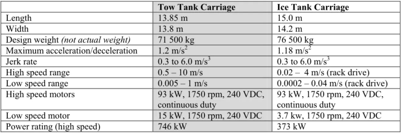
Both carriages were designed and installed by Mitsui Shipbuilding and Engineering Ltd. from 1983 to 1985. Table 1 summarizes the parameters of those systems.
Tow Tank Carriage Ice Tank Carriage
Length 13.85 m 15.0 m
Width 13.8 m 14.2 m
Design weight (not actual weight) 71 500 kg 76 500 kg Maximum acceleration/deceleration 1.2 m/s2 1.18 m/s2
Jerk rate 0.3 to 6.0 m/s3 0.3 to 6.0 m/s3
High speed range 0.5 – 10 m/s 0.02 – 4 m/s (rack drive) Low speed range 0.005 – 1 m/s 0.0002 – 0.04 m/s (rack drive) High speed motors 93 kW, 1750 rpm, 240 VDC,
continuous duty 93 kW, 1750 rpm, 240 VDC, continuous duty Low speed motor 15 kW, 1750 rpm, 240 VDC 3.7 kw, 1750 rpm, 240 VDC Power rating (high speed) 746 kW 373 kW
Table 1: parameters of the Mitsui systems, 1985
Both carriages are mounted on 4 two wheel bogies running on steel rails along the length of the tanks. In high speed operation, each wheel of the tow carriage is driven by a separate DC motor, eight in total. In low speed operation, 2 separate motors, disconnected by a clutch during high speed runs, drive 2 wheels. Control system feedback, provided by an incremental encoder (pulse generator) connected to a measurement wheel, was used to calculate speed, position, acceleration and travel distance remaining. Inner loop feedback was provided by one of the tachogenerators attached to the drive motors.
The ice carriage, in high speed operation, is propelled by the 4 wheels of the 2 bogies at one end of the carriage. Each of the four wheels is driven by a separate DC motor. Low speed operation is similar to that of the tow carriage with 2 separate motors driving 2 wheels, one on each of the two west end bogies. Because of low friction in the ice tank environment, propulsion normally uses a rack and pinion drive, where the rack is a toothed rail running the length of the tank on both sides. A manual clutch is used to change from rack drive to wheel drive.
While the Mitsui systems worked well, there were shortcomings which became more significant as the systems aged. Electromechanical relays were used extensively; control firmware was executed by a custom, Z80 based processing board. The firmware was written in machine code which was practically impossible to modify and could only be loaded by a paper tape reader. As tank operations and types of desired testing changed over the years from 1985, the carriage control system remained essentially unchanged. During the institute’s investigation of potential Year 2000 problems, we discovered that the spare CPU boards for both carriages had volatile memory powered by a lithium battery. One of these batteries had died during its 12 year storage, leaving only one spare.
Plans were prepared to replace the carriage control systems with current technology that would be easier to maintain and, most importantly, allow changes to be readily made in high level software. As a result of a call for proposals, a contract was awarded in October 2001 to Controls and Equipment Ltd. of St. John’s to design and implement new carriage control systems.
3. New System
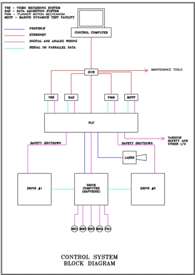
Minimum requirement for the new system was to meet all performance specifications of the Mitsui system while enabling better ability for changes in operation to meet the always changing requirements of a research environment. Three computers are used in the new design. Figure 4 is a block diagram showing system basics. The control computer is an industrial rack mount unit located in the operator’s console. It runs the Windows 2000 operating system and provides user profiles, security, networking control and data logging of carriage operation parameters for maintenance purposes. Main operator input is through a touch screen LCD panel. The graphical user interface (GUI) displays various screen menus for the operator to choose modes of operation and input test run parameters.
Figure 4: system block diagram with Ice Tank details
The control computer does not actually control the carriage. It communicates with the Programmable Logic
Controller (PLC) over a10 baseT Ethernet link, relaying requests to the PLC. The PLC actually controls the carriage in conjunction with the Safphire, a special purpose PLC to be described later.
3.1 PLC
The PLC is at the center of the control system. It receives the control requests from the control computer and acts on them. Specific information regarding carriage speed, accelerations and distances is passed to the Safphire. The PLC controls directly all carriage peripheral equipment such as the brake hydraulic system, low speed clutch, warning horn, motor fans and test frame. It is the PLC’s role to monitor the safety of the carriage and to ensure that the operation modes are enforced at various locations in the tank. This includes operation of the braking system through the emergency stop circuitry.
3.2 Laser Distance Sensor
The Moduloc laser distance sensor is used as part of the carriage position feedback system. It is a highly accurate and repeatable device. Mitsui’s control system used a roller wheel-pulse generator to determine carriage position along the tank. There were repeatability problems with these measurements, possibly due to wheel slippage, now eliminated. The laser sensor now complements the roller wheel rotary encoder data allowing a more reliable calculation of carriage position.
3.3 Safphire
The Safphire is a dedicated motion control computer produced by Brock Solutions, Drives and Automation Group of Kitchener, Ontario. It has the full control over the motors and looks after all speed and position feedback loops. The Safphire receives its control requests from the PLC and implements them on command. The PLC and the Safphire communicate over a high speed RS422 network which runs an industrial protocol known as Profibus.
3.4 Drive Electronics – Motors
The original DC motor drives consisted of two 6 pulse (6 SCR) drives providing full four quadrant operation. They utilized analog control technology. This arrangement was replaced with new 12 pulse digitally controlled drives which also provide full four quadrant operation. The new drives also allowed simple communication with the Safphire. The drives were designed, manufactured and supplied by Brock Solutions. In the Ice Tank the communication medium is copper cable, the Tow Tank utilizes a fiber optic link.
The motors, 240 volt DC armature, shunt wound, 93 kW, were not replaced. Each drive powers 2 motors. The two motors are wired in series and are physically located on opposite sides of the carriage. This arrangement allows a drive to provide equal applied torque to both sides of the carriage. The Tow Tank utilizes 4 motor sets for a total of 746 kW; the Ice Tank utilizes 2 motor sets for a total of 373 kW.
3.5 Motor Encoders
The existing analog feedback tachometers were replaced with 5000 PPR (pulse per revolution) incremental encoders. Using the edge sensing detection technology in the Safphire, this resolution was further increased to 20000 PPR. In addition, the existing tachs were not installed on all motors, only on one motor of each set. The new encoders were installed on all motors. This new arrangement allowed for a maximum speed resolution of 0.5 mm/s in the Tow Tank and 0.2 mm/s in the Ice Tank.
3.6 Operating Modes
Manual Mode: the control system allows various manual modes of operation in which the carriage will run at any set speed, acceleration and jerk rate.
Profile Mode: the usual mode of operation during testing is the profile mode. In this mode a sequence of speeds and accelerations are entered. The control system confirms prior to carriage motion that these actions are safe and do not exceed carriage limitations. The profile is than plotted on the GUI. When carriage motion is enabled, actual carriage motion is plotted over the requested motion on the GUI.
Homing Mode: during the control system refit a homing mode was added. It allows the operator to specify a target position and have the carriage move to that location. It is used in the preparation stages of a test. Previously the carriage had to be moved to a desired location under manual control.
4. Safety Considerations
The carriage braking system employs a combination of regenerative, dynamic and mechanical methods. These techniques are used alone and in combination depending upon the situation. During all normal carriage operations regenerative braking is used alone. This involves using the speed loop to stop the carriage in a controlled manner. The regenerative energy created by the DC motors is absorbed by the power system. During emergency braking, regenerative braking is used for a short time followed by dynamic and mechanical braking.
Various safety interlocks are built into the system, the most critical being fixed magnetic limit switches which detect when the carriage is in danger of being damaged or it is creating a potentially dangerous situation for operations staff. If these conditions are detected the carriage is commanded to enter an emergency stop mode. The position of these switches is such that a safe stop can be made within the confines of the tank.
carriage position, speed and deceleration settings, allowing the operator to utilize as much tank length as possible. 5. Implementation
Contract for the carriage control system was awarded to Controls and Equipment Ltd. in October 2001. Work began in the Ice Tank in January 2002 and proceeded until September 2002. There were interim periods when the tank was used for model tests and for an investigation into replacement of the gearboxes to reduce mechanical backlash. New gearboxes were too expensive and control compensation was implemented, as discussed below. After a successful evaluation period of the Ice Tank system, work began on the Tow Tank carriage in March 2003, with essential completion in June 2003.
5.1 Ice Tank – Back Tension Compensation
The Ice Tank is mainly used for low speed runs through an ice sheet. During this operating condition any backlash in the drive train makes it very difficult to achieve the required speed regulation. The original control system had a back tension compensation circuit implemented with analog control electronics. The new system implemented and improved this compensation.
When performing low speed runs in ice the carriage’s low speed motors are used to propel the carriage. The high speed motors free wheel. The back tension routine uses one set of high speed motors acting as a brake with the low speed motors moving the carriage. The braking force applied by the high speed motors consists of a fixed and a variable component. The variable component is a feed forward input into the back tension loop based on speed error. 5.2 Tow Tank Slip Compensation
With the previous control system, the Tow Tank carriage experienced a slippage phenomenon when high rates of acceleration were attempted. The Tow tank’s mechanical drive train utilizes smooth steel wheels riding on smooth steel rails. The original design specification for the carriage aimed to achieve a maximum acceleration rate of 1.12 m/s/s. In actual practice the maximum acceleration was 0.6 m/s/s. If rates in excess of 0.6 m/s/s were attempted the wheels would slip on the rails resulting in shaking of the carriage and causing an emergency stop. IOT staff believed that higher accelerations were possible and the most probable cause for the slippage problem was uneven loading of the carriage, resulting in different wheels having different breakaway torques.
As stated above, the new design with an encoder on each motor allowed the implementation of a slip compensation routine. The routine was fundamentally simple, adding to its effectiveness. Instead of implementing a standard speed control loop in which there was one feedback source, both encoders in each 2 motor set were utilized in the speed loop. The feedback source is automatically chosen based on the faster motor of the set. Since a set of motors are wired in series and produce the same torque, they should turn at the same speed. Under high acceleration, the motor driving a slipping wheel will turn faster than it’s series partner and will be made the feedback source. This will remove the excess torque from that motor set and stop the slippage condition. Since these decisions are made very quickly, an extreme slippage condition does not have a chance to occur.
With these design changes the requested 1.12 m/s/s acceleration rate was achieved. 6. Results and conclusions
Both the Ice and Tow Tank carriages are now operating with improved and easier to maintain control systems which utilize more solid state electronics and high level software. Increased ability to respond to changing research and model testing requirements, improved operator interface and local technical support are positive features.
Acknowledgements
The authors wish to acknowledge the NRC-IOT Carriage Control Group, Paul Attwood, Spencer Butt, Peter Hackett, Brian Hill and Jim Millan, for preparing the specifications and overseeing this project. Special thanks are due to the staff of the Ice and Tow Tanks for their help in installation and testing of the new systems, as well as for their valuable suggestions on operational procedures.