The Analysis and Implementation of Generic MPEG Header
And Transport Layer Decoders
by Yuan Feng
Submitted to the Department of Electrical Engineering and Computer Science in Partial Fulfillment of the Requirements for the Degrees of
Bachelor of Science in Electrical Science and Engineering
and Master of Engineering in Electrical Engineering and Computer Science at the Massachusetts Institute of Technology
May 11, 1999
C Copyright 1999 Yuan Feng Allrights reserved.
The author hereby grants to M.I.T. permission to reproduce and distribute publicly paper and electronic copies of this thesis
and to grant others the right to do so.
Author_
epartment of Eleqtrical Engineering and Computer Science May 11, 1999 Certified by_
Madhu Sudan Associated Professor Department of Electrical Engineering and C6mput/r Science
Thesis Supervi r Accepted by(
Chairmn D e CArthur C. Smith
Chairman, Department Committee on Graduate Theses
The Analysis and Implementation of Generic MPEG Header
And Transport Layer Decoders
Submitted to the
Department of Electrical Engineering and Computer Science
May 11, 1999
In Partial Fulfillment of the Requirements for the Degree of
Bachelor of Science in Electrical Science and Engineering
and Master of Engineering in Electrical Engineering and Computer Science
ABSTRACT
Computer technology has progressed to a point that use of video and audio is practical.
An average personal computer can receive, store, manipulate and playback audio and
video well enough to dramatically change multimedia communication. IBM Research's
Community-Based Customer Access Solutions Department has embarked on research to
contribute to this emerging field. Initial work of the research includes the development of
a system to broadcast digital video and audio streams by satellite. This paper describes a
portion of that research, including: the design of digital audio and video compression
technology, tools created to analyze, decode, encode and manipulate audio and transport
streams encoded in MPEG compression and transport formats.
Thesis Supervisor Madhu Sudan
Title: Associate Professor, MIT Department of Electrical Engineering and Computer
Science
Acknowledgments
First and foremost, I would like to thank my entire group at IBM Research for allowing me this opportunity to work on this thesis project. Geoffrey Purdy, Edward Clarke, Robert Flavin, Perwaiz Nihal and Nobert Vogl have continually supported me throughout the design, implementation and write-up phases of this project. My manager Geoffrey, and my direct supervisor Bob tirelessly guided me through the entire project. They always had time for me whenever I needed their advice and input. Bob often grilled me on my thesis progress. Geoffrey read and commented on every draft of my thesis write-xp. This thesis project would not be possible without their support, encouragement and guidance,
as well as their constant reminder of my thesis deadline. Thanks to Ed, I finally understood that a picture was indeed worth a thousand words.
I would also like to thank my thesis advisor, Madhu Sudan from MIT. Without his full
understanding and interest in my project, this thesis would never be complete. At every step of the process, he is there to offer me advice and help. Without his input, I would have never reaped the full benefits associated with such a thesis project. His comments helped me to fully integrate my thesis work at the end.
Tristan Savatier and Gilles Boccon-Gibod from mpegtv.com have helped me to resolve certain technical issues during the initial stages of my thesis work. Thanks to them, my thesis work has gone rather smoothly.
Many thanks to the staff members at the MIT EECS department, especially Anne, Josephina and Lydia. Their coordinated efforts and superb administrative skills allowed me to stay focused at my work.
I would also like to take a moment to salute to F.T., my car and kroll, my computer. Without their unswerving dedication, I would probably be stuck somewhere on the road between Boston and New York, or reinstalling software instead of writing this
acknowledgment.
Finally, I owe my family and friends everything I have. I just hope I would have a chance to give a little back to them someday. To those of my friends who have endured this arduous ordeal with me: We have made it! Time to get ready for the next challenge.
Table of Content
C hapter 1. Introduction ...
5
Chapter 2. Background ...
8
2.1 MPEG Overview ... 8
2.2 Audio O verview ... 10
Chapter
3.
Phase I--MPEG Audio Header Decoder ...
is
3.1 MPEG Audio Overview... 153.2 Coded Audio Bit Stream Syntax ... 19
3.3 Design and Implementation... 22
3.3.1 Functionality Specification ... 22
3.3.2 Main Data Structure ... 22
3.3.3 Main Routines ... 23
3.4 Simulation Results ... 26
3.5 Conclusion ... 33
Chapter 4. Phase 1--MPEG Transport Stream Decoder ...
35
4.1 MPEG System Layer Overview ... 35
4.2 Transport Stream Syntax ... 37
4.2.2 Program Specific Information ... 41
4.2.3 Packetized Elementary Stream Syntax... ... 49
4.2.4 Adaptation Field Syntax ... 53
4.3 Design and Implementation ... 53
4.3.1 Functionality Specification ... ... 53
4.3.2 Main Data Structure ... ... 54
4.3.3 Main Routines ... 54
4.4 Simulation Results ... 60
4.5. Conclusion ... 61
Appendix A. Discrepancies ...
63
Appendix B. Transport Stream Adaptation Field ...
64
Appendix C. Packetized Elementary Stream...
68
Appendix D. Related W ork ...
73
Appendix E. Code For Phase I and 11 Implementation ...
87
Chapter 1. Introduction:
The Internet has revolutionized the telecommunications world and has become the catalyst for the genesis of a new social order. The invention of the telegraph, telephone, radio and computer set the stage for this unprecedented integration of capabilities. Even though from a purely technical perspective, the Internet merely offers an alternative mechanism for the sharing of data on a worldwide scale, it really, once and for all, promises a radically new information infrastructure for collaboration and interaction between individuals and communities which is not confined to geographical locations and
by other physical constraints. Given that the "Galactic Network" concept of the social
interactions through networking was proposed by J.C.R. Licklider of MIT only in August of 1962, rate of deployment and social acceptance of this technology is staggering
Computer technology has progressed to a point that use of video and audio is practical. An average personal computer can receive, store, manipulate and playback audio and video well enough to dramatically change multimedia communication. IBM Research's Community-Based Customer Access Solutions Department embarked on research to contribute to this emerging field. Initial work of the research includes the development of a system to broadcast digital video and audio streams by satellite. This paper describes a portion of that research, including: the design of digital audio and video compression technology, tools created to analyze, decode, encode and manipulate audio
1. Refer to articles, "Man-Computer Symbiosis"[1] and "The Computer as a Communication Device"[2] by J.
and transport streams encoded in MPEG compression and transport formats. MPEG (Motion Picture Experts Group) provides the current international standards for digital audio and video compression as well as the associated transport and storage formats.
Work described in this paper is organized into two phases. The first phase
implements a generic audio header decoder. This decoder decomposes MPEG audio data stream and analyzes the control information in its data structure headers. Based on its analysis, the decoder further generates stream-specific information such as data duration and content type. The second phase implements a generic Transport Layer decoder. This decoder decomposes MPEG Transport Layer stream and analyzes its control structures. Based on its analysis, this decoder generates stream-specific information such as program association, stream content, elementary data type and performs reconstruction of
elementary data streams. In the case when an elementary data stream is encoded in
MPEG audio format, work in the first phase has a direct application on it. Chapters Two,
Three and Four all devote several sections to clarify the terminology mentioned here. Work presented in this paper differs from existing implementations of MPEG decoders and their applications in a fundamental way. Referring to the diagram below, work in this research applies to stage B at the network level, while existing MPEG decoders are applicable at stages A and C.
A C
Server B Client
nvironment Tasiso Environme
Decoders developed in this project complement existing MPEG decoders and their applications. They filter MPEG encoded data streams by decomposing and examining their control information, program association and data content. The Transport Layer decoder even performs reconstruction of elementary data streams but stops short of decoding the elementary digital video and audio data. Instead, existing MPEG decoders and their applications carry out the decoding and presentation of these elementary digital video and audio data. The following example is just one application which demonstrates the above complementary feature.
A C Server Client nvironment Evrne Decoders in this project B
Figure 2: Sample Application
While a client at stage C is receiving data from a serve at stage A, it can establish a simultaneous connection with the decoders in stage B. Decoders at stage B can provide the client with control information of the associated MPEG encoded data stream along with data duration, program association and content information which then allows the client to select from and filter streams received from the server. Once the selected and filtered data stream is received and buffered at stage C, existing decoders and their applications then decode the data stream and present the decoded visual/audio
the decoders at stage B to monitor and analyze the transmission of its encoded data streams.
Furthermore, work in the first phase also addresses ambiguity in the standards on the decoding of header information associated with MPEG-II, Layer-III audio data streams. Refer to Appendix A for a synopsis of the observed discrepancies.
The rest of this paper is organized into the following three chapters. Chapter Two gives an overview of the MPEG technology. Chapter Three describes work related to the first phase of this project. It starts off with a presentation of the MPEG audio structure, followed by design and implementation details of the generic audio header decoder. A discussion of simulation results and future work then conclude this chapter. Chapter Four adheres to the same format as that of Chapter Three when describing work related to the second phase of this project which develops a generic Transport Layer decoder.
Chapter 2. Background
Following is a broad overview of MPEG and audio compression in general. It is meant to familiarize readers who are not technically versed in this particular subject matter before leading them through the intricacies of MPEG standards and specifics of this research.
2.1 MPEG Overview
MPEG is an acronym for a family of International Standards used for coding audiovisual information in a digitally compressed format. The name is an acronym for Moving Picture Experts Group which pioneered the efforts in developing these standards
in 1988. Leonardo Chiariglione, in particular, stands out as the father of MPEG. MPEG-I is formally known as ISO/TEC Standard 11172: Coding of moving pictures and
associated audio for digital storage media at up to 1.5 Mbits/s[3]. It addresses the issue of combining one or more video and audio streams with timing information to form a single stream. The resulting stream is well suited for storage and transmission. Currently,
Standard 11172 has five parts: system, video, audio, conformance testing and software simulation. MPEG-II is formally known as ISO/TEC Standard 13818: Generic coding of moving pictures and associated audio information[4]. It addresses the issue of combining multiple video and audio streams with timing information to form multiple streams
suitable for storage and transmission. There are two forms: Transport Stream and Program Stream. Transport Stream is designed for an error-prone environment, while Program Stream is for a rather error-free environment. Furthermore, Transport Streams can result from combining streams of different time bases, but Program Streams are composed of streams with common time bases. Standard 13818 has nine parts: system, video, audio, conformance testing, software simulation, extension for Digital Storage Media Command and Control (DSM-CC), advanced audio coding, extension for real-time interface for system decoders and conformance extensions for DSM-CC. Finally, the MPEG-IV Standard is still under development and will be numbered as ISO/TEC Standard 14496. MPEG-IV incorporates a key technology that enables the coding of visual objects of arbitrary shape. MPEG-II visual objects are constrained to be of rectangular shape.
The gradual permeation of MPEG and other compression formats to the multimedia industry follow directly from the acceptance of digital technology. Digital
technology has gained solid footing in the industry primarily for two reasons. First, it allows economic, compact and reliable replication of complicated system components. Anyone who has come across analog design would attest to the frustration of fine-tuning one system, let alone replicating one. Second, digital technology enables the possibility of vast net saving in bandwidth in comparison to the analog solution. For example, on a CD, two channels of audio data sampled at 44.1Khz with 16 bits per sample requires a data rate of approximately 1.4 megabits per second. There is a clear need for compression, and a vast array of digital compression techniques are available. Digital visual and audio information have become an integral part of the overall multimedia environment. Along with it, digital compression becomes vital in helping to establish its efficient interchange, distribution and storage.
The major advantage of MPEG over other video and audio coding formats lies in its sophisticated compression schemes. Because of them, the compressed files are much smaller for the same audible and visible quality. Experiments reveal that even at a 6:1 compression ratio, MPEG compressed audio data is indistinguishable from the original by professional listeners. In order to lend further credence to these results, researchers
intentionally selected the most difficult audio data to compress[5,12].
2.2 Audio Compression Overview
A digital representation of audio data begins with the sampling of the analog wave
forms in regular and discrete intervals. Quantization refers to bit-representation of the amplitude of sampled analog wave forms. For example, an eight-bit representation has a total range of 256 steps to approximate the amplitude of an analog sample. Unless it
involves an infinite-bit representation, quantization is an approximation, so has an
associated error, i.e. quantization error. Signal to Noise Ratio, SNR, is one of the standard characterization of signal quality in Digital Signal Processing, DSP[6]. It is a measure of quantization error relative to the signal strength. Observe that the same amount of
quantization error has a greater SNR in relation to signals of lesser amplitude.
One of the digital compression techniques, Pulse Code Modulation, or PCM, is widely adopted to digitize and quantize audio data[7,8]. In the case of a two-bit
representation, PCM specifies four evenly spaced quantization levels as well as assigning a 2-bit code word for each level.
Level code word
0 00
1 01
2 10
3 11
It then divides the range of analog samples into four segments. Quantization occurs when analog values of these samples from different segments are mapped into different code words.
A natural extension from PCM is the u-law compression method specified by CCITT Recommendation G.711[9]. Because of the even spacing in PCM, there is a
greater SNR associated with samples of lower amplitude. In recognition of this fact, the u-law technique employs nonlinear quantization. Logarithmic in nature, distribution of the quantization levels are denser for lower levels. As a result, overall signal quality is much more uniform over the entire amplitude range than that achieved by PCM.
A slightly better scheme, Adaptive Differential Pulse Code Modulation (ADPCM) increases that factor by two. Instead of faithfully coding each sample as in PCM, ADPCM only encodes the difference between each sample and its predicted value. It assumes that neighboring audio samples are generally similar to each other. This assumption is
reasonable when audio data contains smooth transitional tones. The extreme counter example would be sampling a sinusoidal wave form at its peaks and valleys, but this situation is very unlikely in most commercial applications. When the assumption is applicable, encoding only the difference can drastically reduce the lengh of code words, i.e. number of bits used to represent an analog sample. As long as the encoder and decoder both utilize the same set of rules for prediction, the difference is sufficient in reconstructing the original encoded sample value. In its simplest prediction scheme, the previous sample serves as the predictor. ADPCM further enhances compressed signal quality with the capability of adapting to signal characteristics by changing the spacing involved in quantization.
More sophisticated compression techniques rely on psycho-acoustical models for greater efficiency. Human hearing and voice range from 20 Hz to 20 KHz. The 2-4 Khz range is the most sensitive. Dynamic range is about 96dB. Further psycho-acoustical experiments[10, 11] point out that several masking factors dictate the audibility of tones. Masking occurs when a tone is no longer distinguishable because of the presence of another. Frequency and amplitude are two major factors associated with masking.
Frequency masking focuses on how a tone of a fixed amplitude, ie. testing tone, is masked in the presence of a different frequency, i.e. masking tone. Here, the threshold of
These thresholds vary quite a bit over the spectrum. In temporal masking, a testing tone is still masked a short period after the presence of a masking tone. Again, the exact delay in audio perceptibility is dependent on both frequency and amplitude of the masking tone. Steinmetz and Nahrstedt[12] recorded experimental results in their notes. The above observations lead to the partitioning of the audible spectrum into critical bands in order to better characterize the resolving power of the ear as a function of frequency. Finer
partitioning better models the masking effects but also results in greater complexity. Sub-band coding exploits these psycho acoustical phenomenon by designing filter banks to partition the audio data spectrum into bands approximating critical bands of human hearing. Psycho-acoustical models are then applied to sub-bands individually in order to ensure the best quantization results in light of various masking effects.
Both Layer-I and Layer-II of the MPEG audio standards employ this method. In Layer-I, the filter bank partitions the audio spectrum into 32 constant-width sub-bands. For every 32 input audio samples, a Layer-I encoder provides 32 frequency samples, one per sub-band. Each group of 12 samples from one sub-band would then receive one bit allocation along with a 6-bit scale factor if necessary. If a sample value is zero, then scale factors are omitted. A Layer-I frame then consists of 32 groups of 12 samples, i.e., 384 samples. The technical definition of a frame is a part of the audio signal that corresponds to a fixed number of audio PCM samples. More intuitively, a frame is the smallest decodable unit in an audio stream. A Layer-II algorithm enhances Layer-I by coding data
in larger groups. It codes 3 groups of 12 samples from every sub-band into 1 bit allocation. Each frame has dimension of 3 by 12 by 32, or 1152 samples. Stereo
redundancy coding in MPEG audio is slightly more involved, but follows from the same logic.
Being the most complicated of the three, Layer-III extends both Layer-I and Layer-iI with the incorporation of transform coding. It applies aModified Discrete Cosine Transform (MDCT) to the filter bank outputs, thus compensating for certain filter bank deficiencies[13]. The constant-width frequency bands constructed by the filter bank do not match an ear's critical bands perfectly. The band width is too wide for lower frequencies. Thus the number of quantizer bits is insufficient for the level of noise sensitivity within the sub-band. Also, there is significant overlap between adjacent filter bands. Therefore, signals at a particular frequency can have rippling effects on several neighboring bands. The MDCT's provides better spectral resolution by further
subdividing the filter bank outputs. Since there is always a tradeoff between time and frequency resolution, MDCT utilizes two block lengths, a short block of 12 samples and a long block of 36. The short length is designed for transients where better time resolution is more important. Aside from this extension, the filter bank for Layer-III is similar to that of Layer-Il. Each frame contains only 1152 samples.
As a side note, there are two types of digital compression, lossless and lossy. All of the above compression methods are lossy because loss of data is tolerable when
dealing with audio data. On the other hand, lossless compression methods are primarily for files whose digital makeup must be preserved, such as an executable string.
Decompressing a losslessly compressed file yields the exact original. The downside, meanwhile, is the 2:1 compression ratio achieved by these methods. There are other major branches in audio lossy compression other than those discussed above. One in
particular concentrates on speech recognition. Examples of it include Linear Predictive Coding and Code Excited Linear Predictor, which attempt to best fit signals to speech models. They have little relevance to this particular thesis project and are only mentioned for the purpose of completeness.
Chapter 3. First Phase-MPEG audio header decoder
3.1 MPEG audio Overview 1
Figures 3 and 4 below represent the block diagrams for the generic audio encoder and decoder. Input audio samples are fed into the encoder. Mapping then converts these samples from time to frequency domain. The mapped samples are referred to as sub-band samples in Layer-I and I because these two layers employ subband filtering as
mentioned in Section 2.2. By analogy, those in Layer-II are called transformed sub-band samples, again because of the additional MDCT involved in the mapping process in that layer. As the block diagram points out, a psycho-acoustical model generates a set of control data for the quantizer and coding process. In essence, a psycho-acoustical model attempts to describe sensitivity levels related to human hearing as qualitatively accurate as possible. The more accurate this description is, the more efficient the encoding process is. Section 2.2 briefly touched upon certain criteria essential to a psycho-acoustical
model.
1. Specifications are referenced from ISO/TEC 11172-3:1993, Audio[3] and ISO/TEC 13818-3:1998, Audio[4].
Figure 3: Block Diagram for A Generic MPEG Audio Encoder
Figure 4: Block Diagram for A Generic MPEG Audio Decoder
The bit stream data input to the decoder consists of frames. Notice how closely the decoding process mirrors the encoding process. This close matching is expected since a decoder aims to reverse the encoding process with minimal loss of information.
Figure 5 extends Figures 3 and 4 with a more in-depth look at the sub-processes within each block.
INPUT ENCODED (GET BIT STREAM
BIT STREAM
FIND HEADER
DECODING OF DECODE BIT STREAM FORMAT INFO
BIT ALLOCATION
-i
(DECODE SCALE FACTORS )
DECODING OF SDECODE SAMPLES)
SCALE FACTORSI
(INVERSE QUANTIZE SAMPLES REQUANTIZATION
OF SAMPLES (REORDER, conditional)
SYNTHESIS SUBBAND
FILTER (YTESIZE VIA MDCT &
OVERLAP-(SYNTHESIZE VIA POLPHASE MDCT I
OUTPUT PCM SAMPLES
END9
Layers 1/11 Layer IlIl
Figure 5: MPEG Decoder Flow Chart
As a reminder, the term, "MPEG audio" in this research, refers collectively to ISO/TEC
standards 11173-3, i.e. MPEG-I audio and 13818-3, i.e. MPEG-II audio. MPEG-Il audio extends MPEG-I audio by providing three lower sampling frequencies.
MPEG-I Table 1: bit rates for MPEG- and MPEG-Il
MPEG Layer-III supports variable bit rate. In other words, frames from the same audio stream data can contain audio data of different bit rates. So far, most MPEG audio data examined are uniformly encoded. Most examined decoders available in public domain assume uniform bit rate within the same audio stream data. First Phase of this research takes into consideration the existence of variable bit rate encoded audio stream data.
3.2 Coded Audio Bit stream Syntax
In order to better understand the structure of a frame, let's start with a graphical audio sequence()
{
while (true) { frame() frameo{
header() errorcheck() audio-data() ancillary-data() headero syncword ID layer protectionbit bitrateindex sampling-frequency padding-bit private_bit 12 syncword mode mode_extension 1 ID copyright 2 layer original/home I protection_bit emphasis 4 bitrateindex 2 sampling-frequency padding-bh 1 privatebit 2 mode 2 mode-extension copyright onglnallhome emphasisbit allocation of header Figure 6: MPEG Audio Sequence Header
representation of it.
First phase of this research focuses on the decoding of the header section of a frame. The header section consists of the first 32 bits of a frame which are common to all layers. It contains information sufficient to enable a standard decoder to properly interpret the audio data and perform a lossy reconstruction of the original PCM audio samples. This information is also sufficient to construct additional stream-specific information
which is of interest to this research, such as playback duration of the audio stream data. Here are definitions to the header information:
Syneword-- Used to identify the start of a frame, it consists of the bit string '1111
1111 1111'.
ID--A bit value of '1' indicatesMPEG-I audio; a bit value of '0' indicates MPEG-U audio.
Layer-It consists of two bits which identify the layer number based on the
following mapping. '11' Layer-I
'10'
Layer-II'01' Layer-I '00' reserved
Protection_bit--A bit value of '1' indicates that no redundancy has been added to facilitate error detection and concealment; a bit value of '0' otherwise.
Bitrate_index-The four-bit value serves as an index to the bit rate tables
displayed above.
Sampling.frequency--Similar to the bitrateindex, this two-bit value serves as an index to the sampling frequency mapping below.
MPEG-I MPEG-H '00' 44.1 Khz 22.05 Khz
'01' 48 Khz 24 Khz
'10' 32 Khz 16 Khz
'11' reserved reserved
Paddingzbit -It's used to adjust the mean bit rate to the sampling frequencies of 44.1 Khz in MPEG-I and of 22.05 Khz in MPEG-il. A bit value of '1'
value of '0' truncates the number. A slot in the frequency domain is very much analogous to a sample in time domain. The number of slots indicate the distance between two consecutive syncwords. Concrete examples of calculating slots are in Section 3.3.3.
Privatebit-It's a bit for private use.
Mode--The two bits serve as index to the following mapping.
'00' stereo
'01' joint_stereo
'10' dual-channel '11' single-channel
Mode_extension-These two bits are applicable only when the mode is joinLstereo.
Layer-I, II
'00' sub-ands 4-31 in intensitystereo, bound=4
'01' sub-bands 8-31 in intensity-stereo, bound=8
'10' sub-bands 12-31 in intensity _stereo, bound=12 '11' sub-bands 16-31 in intensitystereo, bound=16
Layer-III
'00' intensitystereo off, ms-stereo off
'01' intensitystereo on, msstereo off
'10' intensitystereo off, ms-stereo on '11' intensity_stereo on, msstereo on
Copyright-A bit value of '1' indicates copyright protection; '0' otherwise. Originat/home--A bit value of '1' means the audio data is original; '0' otherwise.
Emphasis-A two-bit value indicates the type of de-emphasis used.
'00' no emphasis
'01' 50/15 microsec, emphasis
'10' reserved
3.3 Design and Implementation
This section presents the design and implementation of the header decoder in the first phase.
3.3.1 Functionality Specification
Input: audio stream data encoded according to ISO/TEC 11172-3 and 13818-3 specifications.
Output: stream specific information including stream header information and playback duration.
3.3.2 Data Structures
Following is a list of main data structures defined for the first phase of this thesis project.
headerinfo-data structure to store the header information
MPG1-biLtrate and MPG2_bitrate tables--tables according to Table 1 above MPGjlayer table--table according to the specification in Section 3.2
MPGforbidden-layers table--table which contains the combinations of total bit rate and mode which are allowed for MPEG-I, Layer-II.
free format all modes 32 kbits/s single_channel
48 kbits/s single-channel
56 kbits/s singlechannel 64 kbits/s all modes
80 kbits/s single.channel
96 kbits/s all modes
112 kbits/s all modes
160 kbits/s 192 kbits/s 224 kbits/s 256 kbits/s 320 kbits/s 384 kbits/s all modes all modes
stereo, intensity stereo, dual channel stereo, intensity stereo, dual channel stereo, intensity stereo, dual channel stereo, intensity stereo, dual channel
3.3.3 Main Routines
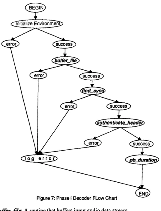
Following is a list of main routines defined for the first phase of this research. First, the following diagram depicts the chain of execution in the MPEG stream decoding process.
Figure 7: Phase I Decoder FLow Chart
Bufferfile: A routine that buffers input audio data stream.
readbits: A routine that reads in the number of bits specified and returns them in decimal representation.
findsync: This routine scans the data stream and locates the first occurrence of a syncword. Because the buffer storing the data is of type char, it's necessary to take care of the two different bit-representations of OxFFF, OxFFFO and OxOFFF. Once an occurrence
of a syncword is located, findsync then evokes authenticate-head to test if the syncword found is a a real syncword.
authenticate_head: Once findsync locates a possible syncword, this routine then verifies the authenticity of the syncword. Initial tests involve check for forbidden
sampling frequencies, bit rates, and combinations of bit rates and modes. The final and most sophisticated check involves the location of consecutive syncwords based on
calculation of slots. The core of the test is as follows:
//Check if Layer-I
if (head->layer ==1)
syncdistance=48*head->bitrate*1000/head->Sampjfreq; (a) // Check if MPEG-I and Layer-III
J
else if (!head->ID && (head->layer == 3)) {sync_distance=72 *head- >bitrate*1000/head->SampLfreq; (b) } else {
// Otherwise
syncdistance=144*head->birate*1000/head->SampLfreq; (c)
}
By definition, one slot is equal to one byte in Layers-Il/Ill, and four bytes in Layer-I. Using N to indicate the number of slots, then the following equations hold,
N = 12*bitrate/sampling.frequency; (Layer-I) N = 144*bitrate/samplingfrequency; (Layer-il/iII)
These two equations help to derive statements (a) and (c) in the above test by equating one slot with one byte for Layers-IlIIlI and with four bytes for Layer-I. The fact that each
frame contains information for 384 samples in Layer-I and 1152 samples in Layers-II/III form the basis for the derivation of the above equations. During test runs to decode header information of some sample audio streams, however, statement (c) does not predict correctly the location of consecutive syncwords in MPEG-Il, Layer-Ill audio data
streams. In fact, when there is no padding, it skips every other syncword. In the case when padding bits of consecutive frames alternate from bit value '1' and '0', stateme*) clearly would never be able to predict the location of consecutive syncwords correctly. This miscalculation, I suspect, is the culprit behind the differences in MPEG-II, Layer-III audio file sizes calculated using various commercial decoders. According to Standard 11172-3 specification, Layer-III utilizes two granules in its encoding algorithm. When extended to lower sampling frequencies, however, Layer-III only uses one granule, therefore
effectively reducing the number of slots per frame by a factor of two. This detail is lost in the Standard 13818-3 specification. MPEG experts from mpg.com under Tristan's
direction clarified this ambiguity'. Upon authenticating the syneword, authenticate_head then decodes the header information and stores it into the headerinfo data structure.
pb.duration: playback duration calculates, to the accuracy of millisecond, the length of an audio data file from the first frame to the very last. The total file size along with the bit rate of a clip are sufficient to generate a rough estimate of the overall playback duration of the piece. A more accurate method utilizesfind-sync and
authenticate_head to first calculate the total number of non-null frames present in the clip. That information, along with the number of slots in one frame, will yield a more accurate estimate of playback duration. To take into account the occurrence of variable bit rates, pbduration offers the option of checking the bit rate on a frame by frame basis.
3.4 Shnulation results
Following contains some simulation results performed on some testing data. Presentation of each result includes three sections, samples of testing data, simulation
output and verification. Samples of testing data are in hexadecimal format. The first column specifies the location of data bytes.
funky.mp3
sample of testing data: FFFB7054 0000007D 082F0000 00555181 AA9ECOOO EBCA9ACD 2C7FACAF E6DCD6E5 545877AC A8000119 F4A5FBA9 137E250F 8A050310 87EBB91E 9080300B 8174A122 4116C810 8AE4DAE8 EA108922 6D0A1D39 C30E9A82 8143A702 1586CE06 2040849C EOB86DBD 82036201 64F24114 11232710 31E69121 C4040000 OBC2DB6E 36DOC000 1FE641C8 4E0E8390 043089BB AFAD8C1C 57666367 36603803 290023C3 E157C09C 00417000 00021100 04958480 00BB8960 COOOOOOO 495032AA BBFFFF6D B692A065 04180342 8680A070 E3FBOA8A 5B862524 A440497D 70C120A0 84014008 18C5D020 EA7347AA 48805116 CE68136E 09BE098A 8E159C3C 2B6D7D23 B93F9D5A 347AD901 C236989A 9162EAC5 1E15ACC8 20C8C000 30283132 06985F80 481904AD OB3FDOBD E8340B82 ED146120 2A01C663 84486663 80000000 000OD9FO 1AFFFB72 740D8001 simulation output: Input File Name: funky.mp3
input audio file size is 744626 bytes SYNCWORD found at 0
ID is MPG-1. layer is 3
redundancy has not been added bitrate is 96 kbits/second
Sampling frequency is 44100 Hz padding is not introduced
private bit is 0 mode is jointstereo
intensitystereo on; ms_stereo off no copyright protection
original
type of de-emphasis used: no emphasis
playback time is 61 secs and 72 millisecs verification: 0000: 0010: 0020: 0030: 0040: 0050: 0060: 0070: 0080: 0090: OOAO: OOBO: OOCO: 0ODO: OOEO: OOFO: 0100: 0110: 0120: 0130:
audio frame header:OxFFFB7054 OxFFF I 01 1 0111 00 0 0 01 01 0 1 00 synword ID: MPEG I layer: Layer Il protectionbit: no redundancy bit_rate: 96 kbits/s sampling-frequency: 44.1 kHz padding-bit: no padding privatebit: not used
mode: Jointstereo
mode_extension: sub-bands 8-31 in intensity-stereo, bound=8 copyright: no copyright
original: original emphasis: no emphasis
syncdistance=144 * bit_rate / samplingjfrequency
=313 or 0x139 bytes
The next syncword OxFFFB7274 has its padding-bit equal to 1, so the syncdistance to the next syncword is 314 or Ox13A bytes away which is located at address 0x273.
classicl.mp3 sample data: FFF37274 9E1F8660 8B8D845A 24C2C638 D04F8842 3670C311 4D70123D ABFBOC7E B6DA482B BE7EFEAF 78F41492 449355E5 ODOD7C7F 00801502 279AE3EC 030B0221 6A24C977 0C87A50E EC6BEC43 00244464 4179D5B0 733272AF 8269BF52 9A4723FF 4F2FC324 ACAEA862 43E31146 605AFFED D47DC648 9C02090C 6E65C145 68A6CCEC 8418E094 9FDDCA38 7A93B7C7 F3727409 OOOE88FE A5018613 48CBOA12 6D546943 865F89D2 BC08F5A1 B9ABOE2F A6CCD24D 5D410A4F B28C28D2 722FB918 OD50A15A 0000: 0010: 0020: 0030: 0040: 0050: 0060: 0070: 0080: 0090: 0OAO: 00B0:
simulation result: Input File Name: classicl.mp3 input audio file size is 138972 bytes SYNCWORD found at 0
ID is MPG-2. layer is 3
redundancy has not been added bitrate is 56 kbits/second
Sampling frequency is 22050 Hz padding is introduced
private bit is 0 mode is jointstereo
intensity-stereo on; msstereo on no copyright protection
original
type of de-emphasis used: no emphasis
playback time is 19 secs and 33 millisecs verification:
audio frame header: OxFFF37274
OxFFF syncword
0 ID: lower sampling frequencies 01 layer: Layer Il
1 protectionbit: no redundancy
0111 bitrateindex: 56 kbits/s
00 sampling-frequency: 22.05 kHz 1 padding-bit: padding
0 private-bit: not used
01 mode: jointstereo
I mode-extension: intensity-stereo on, msstereo on 0 copyright: no coypright
1 original: original
00 emphasis: no emphasis
syncdistance=72 * bitrate / sampling-frequency + 1
=183 or OxB7 bytes 15-kz-064.mp2 sample data: 0000: 0010: 0020: 0030: 0040: 0050; 0060: 0070: 0080: 0090: OOAO: 0OBO: 00CO: 0ODO: OOEO: 0OFO: 0100: 0110: FFFD4800 00000009 ECC73A35 E3DFF8E9 518BE428 D7CD6B5A 5F35AF9A EDAB61B4 EAB635AD E775C167 OEEEEEEB AD6B5DDD AD6B5AD6 AD6B5AD6 EDD0340D 0347DBA0 0D00068F 6CO01AOO 443324A2 6B029BCO EECD77E3 7D460ECE F8FA7E77 D6B5AD6B D6B5AD6B F85A9986 7CD6BD6B 739D01CE 62D8D6B5 DDD6C5B1 BBBBBBAD B5AD0000 341A0000 681A6834 B740D034 OD1F6E81 0120: FFFD4800 66226DB6 51249249 A6B931DF 1DE4F7FE 8BA421F9 77775B16 5AEEEEEE 5AD6B5A3 673C5B0A 9AD6B5AD 80E73A2E F35AF9AD AD6BE6B5 8B635AD7 00002D80 00000000 00000000 20900000 4C6FE49F 35DF948F 087B4A2E C6B5AF9A B62D8D6B 56B6A78E 83C3BC3A 6B5ADE77 739CE72E 6B5AD6B5 F35AD6B5 CD6BE6B5 034001A3 5B000680 0000B600 D0680000 00000001 A069AODO 00000000 COO1C6C8 012AAAAA simulation result:
input audio file size is 120097 bytes SYNCWORD found at 0
ID is MPG-1. layer is 2
redundancy has not been added bitrate is 64 kbits/second
Sampling frequency is 32000 Hz padding is not introduced
private bit is 0 mode is stereo
no copyright protection not original
type of de-emphasis used: no emphasis
playback time is 14 secs and 86 millisecs verification:
audio frame header: OxFFFD4800
OxFFF syncwor 1 ID: MPE 10 layer: La 1 protectic 0100 bit.rate: 10 samplin 0 padding. 0 privateI 00 mode: s 00 modee 0 copyrigh 0 original: 00 emphasi d G I yerll n_bit: no redundancy 64 kbits/s g-frequency 32 kHz _bit: no padding
bit: not used tereo xtension: sub-bands t: no copyright no original s: no emphasis 4-31 in intensity-stereo, bound=4
sync-diStance=1 44 * bitrate / sampling-f requenCy
=288 or Ox1 20 bytes
sample data: 0000: 0010: 0020: 0030: 0040: 0050: 0060: 0070: 0080: 0090: OOAO: OOBO: OOCO: 0ODO: 00EO: OOFO: 0100: 0110: 0120: 0130: 0140: 0150: 0160: 0170: 0180: 0190: 01AO: OBO: OCO: 01DO: 01EO: 01FO: 0200: 0210: 0220: 0230: F7DF7D6C C5B16C5B EF7BDEF7 2D8B62D8 8B62D8B6 DEF7BDEF 5B16C5B1 16C5B16C BDEF7BEF B62D8B62 5B16C5B1 16C5B16C BDEF7BDE B62D8B62 2D8B62D8 7BDEF7DF 6C5B16C5 7777BDEF BEFBEFAD D8B62D8B FFF488C4 53D24566 55555555 555555F7 F7DF7DF7 DF7DF7DF BDEF7BDE F7BDEF7B DF7D6C5B 16C5B16C B16C5B16 C5B16C5B 7BDEF7BD EF7BDEF7 8B62D8B6 2D8B62D8 62D8B62D 8B62DBEE F7BDEF7B DEF7DF7D 16C5B16C 5B16C5B1 C5B16C77 77BDEF7B EF7BEFBE FBEFAD8B 2D8B62D8 B62D8B62 BBDEF7BD EF7BDEF7 7DF7D6C5 B16C5B16 5B16C5B1 6C5B16C5 F7BDEF7B DEF7BDEF D8B62D8B 62D8B62D B62D8B62 D8B62D8E EF7BDEF7 BDEF7DF7 B16C5B16 C5B16C5B 6C5B16C7 777BDEF7 DEF7BEFB EFBEFAD8 62D8B62D 8B62D8B6 BBBDEF7B DEF7BDEF 0240: FFF488C4 53D24566 B6DBB7FF FFFFFFF5 simulation result: Input File Name: verdl6m.mus input audio file size is 100224 bytes SYNCWORD found at 0
ID is MPG-2.
layer is 2
redundancy has been added bitrate is 64 kbits/second Sampling frequency is 16000 Hz padding is introduced private bit is 0 mode is singlechannel no copyright protection original B6DBB7FF FFFFFFF5 DF7DF7DF 7DF7DF7D 7DF7DF7D F7CB63BB DEF7BDEF 7BDF7DF7 5B16C5B1 6C5B16C5 16C5B1DD DEF7BDEF BDEFBEFB EFBEB62D B62D8B62 D8B62D8B EF7BDEF7 BDEF7BDE F7DF5B16 C5B16C5B 6C5B16C5 B16C5B16 DEF7BDEF 7BDEF7BD 62D8B62D 8B62D8B6 D8B62D8B 62D8B63B BDEF7BDE F7BDF7DF C5B16C5B 16C5B16C B16C5B1D DDEF7BDE 7BDEFBEF BEFBEB62 8B62D8B6 2D8B62D8 EEF7BDEF 7BDEF7BD DF7DF5B1 6C5B16C5 16C5B16C 5B16C5B1 BDEF7BDE F7BDEF7B B62D8B62 D8B62DB 2D8B62D8 B62D8B63 7BDEF7BD EF7BDF7D 6C5B16C5 B16C5B16 5B16C5B1 DDDEF7BD F7BDEFBE FBEFBEB6 D8B62D8B 62D8B62D EEEF7BDE F7BDEF7B 7DF7DF5B 16C5B16C B16C5B16 C5B16C5B 7BDEF7BD EF7BDEF7 8B62D8B6 2D8B62D8 62D8B62D 8B62D800
type of de-emphasis used: no emphasis
playback time is 12 secs and 31 millisecs verification:
audio frame header: 0xFFF488C4
OxFFF syncword
0 ID: lower sampling frequency 10 layer: Layer 11
0 protection-bit: redundancy
1000 biLrate: 64 kbits/s
10 sampling-frequency: 16kHz
0 padding-bit: no padding
0 privatebit: not used
11 mode: singlechannel
00 modeextension: sub-bands 4-31 in Intensity-stereo, bound=4
0 copyright: no copyright
I original: original
00 emphasis: no emphasis
sync-distance-1 44 * biLrate / sampling-frequency
-576 or 0x240 bytes
3.5 Conclusion
Carried out in parallel to other phases of the research, the current implementation the generic header audio decoder has been tested against stored data files only. Integration
with the rest of the group project requires some additional work resolving issues associated with handling of network data. Specifics include consideration of buffer overflow and synchronization issues. Also, there needs to be an additional handler to
piece together the MPEG encoded data from packetized network traffic data. The design and implementation of this handler can simply follow the groundwork laid in the second phase of this research which deals with the assemblage of packetized data based on MPEG Systems specifications. Issues surround the adoption ofpb-duradon to handle network traffic is nontrivial as compared to those mentioned in buffer-file. The fundamental issue is how to differentiate one clip from another as they are played in continuous succession. Possible checks include header mapping, checking the garbage in between clips, sensing the delays in between sound clips.
Chapter 4. Phase II--MPEG Transport Stream Decoder 4.1 MPEG Systems Layer Overview'
In this documentation, MPEG Systems layer refers specifically to the Systems part of the international standard, ISO/IEC 13818. It addresses the combining of one or
multiple Elementary Streams of video and audio into single or multiple streams which are
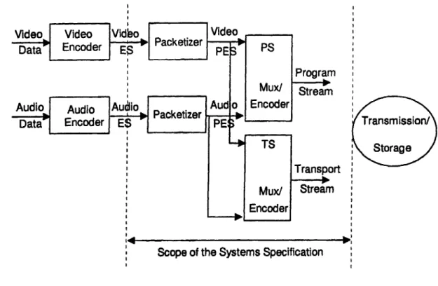
suitable for storage and transmission. The following diagram depicts the scope of the Systems specifications.
Transmission/ Storage
Scope of the Systems Specification
Figure 8: Scope of the Systems Specification
As mentioned in Section 2.1, Program Stream and Transport Stream make up the two
forms of system encoding in this specification. The Program Stream, PS, is analogous to ISO/IEC 11172 Systems layer. It results from combining one or more streams of PES packets which have a common time base into a single stream. PES stands for Packetized
Elementary Stream. Program Stream packets can be of variable length and are for
transmission/storage in a relatively error-free environment. The Transport Stream, TS, combines one or more programs of independent time bases into one single stream. Each program is made up from PES packets of Elementary Streams of a common time base. Each Transport Stream packet is of 188 bytes in length. It's designed for error-prone environments. Notice how the Systems layer is transparent to the content carried within Elementary Streams. This level of transparency allows data transmission schemes such as MPEG over MPEG, IP over MPEG, etc. There are three major decoding operations at the Systems layer: retrieval of encoded programs from either a Transport or Program Stream; regrouping within either a Transport or Program Stream, such as outputting multiple Transport Streams, each of which contains only one program from the original Transport Stream; conversion between a Transport Stream and a Program Stream.
Phase II of this research focuses on the first case involving the retrieval of programs from a Transport Stream. The task of retrieving programs from a TS breaks
down to three components:
1. Retrieval of Program Specific Information, PS; 2. Reconstruction of Elementary Streams;
3. Retrieval of decoding control information.
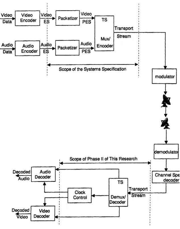
The following diagram gives the overall picture of encoding, transmission and decoding at the Transport layer.
Video
Scope of the Systems Specification
, Scope of Phase ii of This Research *
4.2 Transport Stream Syntax
The following diagram contains the structural layout of a Transport Stream packet. transportpacket()
{
sync-byte transporterrorJndicator payload-uniLstartindicator transportpriority PID transporLscrambling-control adaptation fieldcontrol continuity-counter if (adaptation-fieldcontrol-'1 0' 11 adaptation_field_contro=='1 1'){
adaptation-field}
if (adaptationjfieldcontrol=='01' 1l adaptation_field-control=-'1 1'){
for (i=0;<N;i++){
data-byte}
}
Figure 10: Transport Stream Packet Syntax
Definitions to the terminology shown above are as follows:
Sync byte-This fixed 8-bit field of hexadecimal value, 0x47 indicates the start of a Transport Stream packet.
TransporLerrorjndicator-This is a 1-bit field. A value of 1 reflects the presence of error within this packet. The bit value is set outside of the scope of the
Payloadunit_start_indicator--This is also a 1-bit field. The payload of a
Transport Stream packet may assume two forms, either as a PES packet or a PSI section. PSI stands for Program Specific Information. Refer to Section 4.2.2 for specifics. A value of I by thepayload-unit start_indicator means that the payload of this packet starts with the first byte of either a PES packet or a PSI section. Otherwise, a value of 0 occurs.
Transport priority--This I-bit field has a value of 1 when this packet has a higher priority than other packets with the same PID but with their corresponding fields set to 0. Refer to PID definition below.
PID --This is a 13-bit field whose values serve to identify the type of data stored in the packet payload. It is stream-specific. For example, each elementary stream has its unique elementaryPID. As is clear later in the PSI section, Program Association Tables and Conditional Access Tables use additional flags such as version numbers to
differentiate between multiple tables of the same type.
value description
Ox0000 Program Association Table
Ox0001 Conditional Access Table 0x0002-0x00F reserved
purposes other than those mentioned above, such as 0x001 0-Ox1FFE networkPID, elementary
PID, etc. Ox1 FFF Null packet
TransporLtscrambling.control-This 2-bit field indicates the scrambling mode of the Transport Stream packet payload. The packet header, which includes bits representing
the sync-byte to those representing the continuity-counter, and the adaptationfield are not to be scrambled. value description 00 not scrambled 01 user defined 10 user defined 11 user defined
Adaptation~feldcontrol-This 2-bit field indicates the presence of the adaptation field as well as the payload according to the following table.
value description
00 reserved for future use by ISO/IEC
01 no adaptation field, payload only
10 adaptation-field only, no payload
11 adaptation-field followed by payload
Continuity-counter-This 4-bit field serves as a counter for packets of the same PID. it wraps around to 0 after reaching its maximum value of 15. This counter does not increment when the adaptationtfield-control is set to '00' or '10'. Duplicate packets have their continuity-counters set to the same values. Values for continuity counters of null packets are undefined.
Data-byte-This is the payload of a Transport Stream packet. N is equivalent to
184 minus the number of bytes in the adaptationifield. 184 is from 188 minus the 4-byte packet header. The payload of a Transport Stream packet can contain either data from PES packets, PSI sections, or void in the case of a null packet.
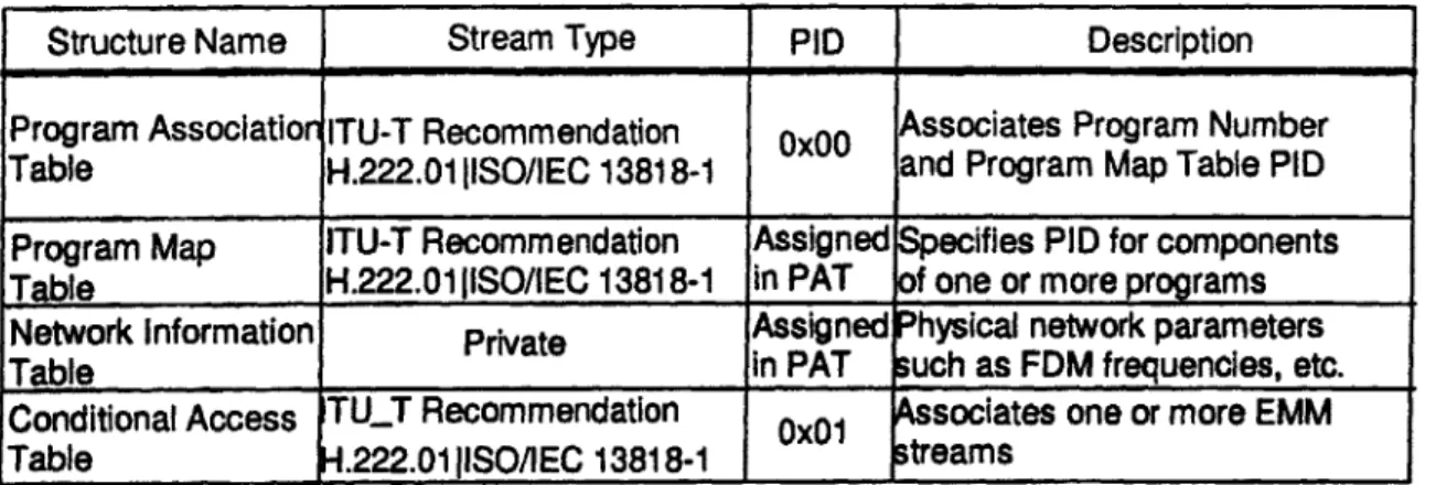
4.2.2 Program Specific Information
Program Specific Information, or PSI is one of the two types of data carried in the
payload of a Transport Stream packet. It contains four table structures, Program
Association Table(PAT), Program Map Table(PMT), Network Information Table(NIT) and Conditional Access Table(CAT).
Structure Name Stream Type PID Description
Program Association ITU-T Recommendation Ox00 Associates Program Number Table H.222.01 IISO/IEC 13818-1 and Program Map Table PID Program Map ITU-T Recommendation Assigned pecifies PID for components Table - H.222.01IISO/IEC 13818-1 in PAT f one or more programs Network Information Private Assigned hysical network parameters
Table in PAT uch as FDM frequencies, etc.
Conditional Access TU_T Recommendation Ox01 Associates one or more EMM Table .222.01|ISO/IEC 13818-1 1
treams
Table 2: PSI Table Structures
Instead of being packetized into PES packets first, these tables are segmented into
sections before being inserted into the payload of Transport Stream packets. Hence, PAS, PMS, NIS and CAS correspond to Program Association Section, Program Map Section,
Network Information Section and Conditional Access Section respectively. Each section
can be of variable length, and starts with a PSI pointer. A PSI pointer is an 8-bit field which indicates the number of bytes following the pointer field up to but not including
the first byte of the first section that is present in the payload of a Transport Stream packet. The syntax for sections of different table structures are somewhat different from each other; each, therefore, warrants individual attention.
A PAT provides the association information between a programnumber and the PID value of the Transport Stream packets which carry the program definition.
program.association-section()
{
tableId section-syntaxjindicator '' reserved section-length transporLstreamjid reserved versionnumber currenLnextindicator sectionnumber lasLsection-number for (1=0; i<N; I++){
program-number reserved if (program-number-'0') network_PID } else{
program-mapPID)
}
CRC-32 }table_id-This 8-bit field takes on values according to the table below. value description Ox00 programassociationsection Ox01 conditionalaccess-section Ox02 TransporLStream-program-map.section 0x03-0x3F ITU-T Recommendation H.222.01 ISO/IEC 13838 reserved
0x40-OxFE User proviate OxFF forbidden
sectionsyntawxjndicator--This
i-bit
field is set to '1'.sectionjength -This 12-bit field specifies the number of bytes immediately following this field up until and including the CRC_32 field. The first two bits of this field should be set to '00', thus yielding a maximum sectionjength value of 1021. The maximum number for a PAS, therefore, is 1024 bytes.
transporLstream_id-This 16-bit field serves to uniquely identify this stream within the network. It is user-defined.
version_number--This 5-bit field identifies the version of the PAT. Whenever there is a change in the program definition, the version_number should increment by 1.
currenLnextindicator --The PAT is currently applicable if this 1-bit field has a value of '1'; not applicable otherwise.
section_number--This 8-bit field serves as a counter. Starting from OxOO, it increments by 1 with each additional section from the same PAT.
last_secdon_number-This 8-bit field specifies the number of the last section of the PAT.
program.number--This 16-bit field, if set to 0x00, indicates the presence of a networkPID. Otherwise, it provides a one-to-one association to the PID of the Transport Stream packet which contains the program definition.
networkPID-This 13-bit field specifies the PID of the Transport Stream packet which contains the NIT.
program-mapPID-This 13-bit field specifies the PID of the Transport Stream packet which contains the program definition.
CRC_32--This 32-bit field is a check for the integrity of the PAS.
A PMT contains a complete collection of program definitions for a Transport
Stream. A program definition is the mapping of one program number to one program element. One program number can have multiple program elements. Examples of program elements include elementary video and audio streams.
TS-program-map-section() table-id section_syntax-indicator '' reserved sectionlength program-number reserved versionnumber currenLnextindicator section-number lasLsectionnumber reserved PCR_PID reserved programinfo-length for (1-0; i<N; i++)
descriptoro for (1=0; i<N; 1++) stream-type reserved elementaryPID reserved ES_infoilength for (=0; i<N2; i++)
{
descriptoro
}
)
CRC-32Figure 12: Program Map Section Syntax
While many fields of PMT and PAT have the same functions, sectionnumber and lasLsection number have different applications in each. In PMT, these two fields are not used and are set to OxOO. In replacement, theprogram_number field is used to identify sections. Section 4.3.3 discusses implementation issues stemming from this special case.
contains the PCR fields valid for this program. PCR, short for Program Clock Reference, provides timing information to the decoder.
program infojlength--This 12-bit field specifies the number of bytes for the descriptor immediately following this field. The first two bits of this field is set to '00'.
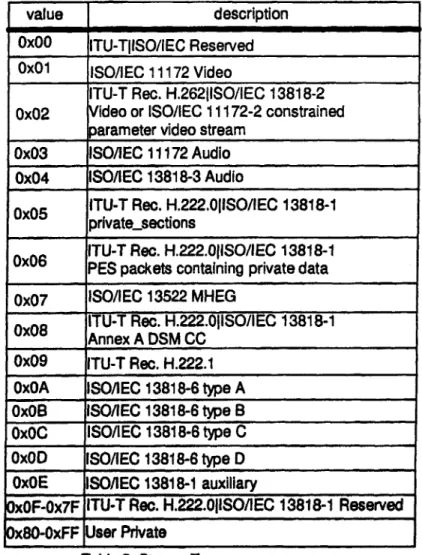
streamjtype--This 8-bit field specifies the type of program element according to the table below. The table below is here for the sake of completeness. Even though Phase I of this research dives into decoding of MPEG header information, stream-level analysis is outside of the scope of phase IL
value description
Ox00 ITU-TIISO/IEC Reserved Ox01 ISO/IEC 11172 Video
ITU-T Rec. H.26211SO/IEC 13818-2 0x02 Video or ISO/IEC 11172-2 constrained
parameter video stream
0x03 ISO/EC 11172 Audio
0x04 ISO/lEC 13818-3 Audio
OxO5 ITU-T Rec. H.222.OIISO/IEC 13818-1
private-sections
ITU-T Rec. H.222.OISO/IEC 13818-1 0x06 PES packets containing private data 0x07 ISO/IEC 13522 MHEG
0X08 ITU-T Rec. H.222.OIISO/IEC 13818-1
0x08 Annex A DSM CC
0x09 ITU-T Rec. H.222.1
OxOA ISO/lEC 13818-6 type A
OxOB ISO/EC 13818-6 type B Ox0C ISO/lEC 13818-6 type C
OxOD ISO/lEC 13818-6 type D
x0E ISO/EC 13818-1 auxiliary
0xOF-Ox7F ITU-T Rec. H.222.0fiSO/EC 13818-1 Reserved 0x80-OxFF User Private
elementary PID--This 13-bit field specifies the PID of the Transport Stream which carries the program element.
ESinfo length--This 12-bit field specifies the number of bytes for the descriptor associated with this program element.
descriptor--These are structures that extend the program definitions.
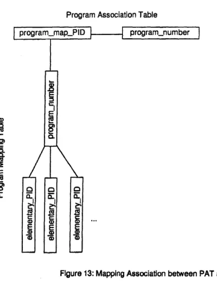
The following diagram illustrates the mapping association between PAT and PMT.
Program Association Table
program-mapPID . program-number
E
CL a
.
E
Fa
Figure 13: Mapping Association between PAT and PMT
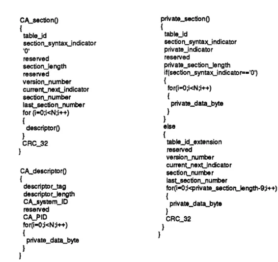
A Conditional Access Table associates between Conditional Access systems with their
EMM streams. EMM stands for Entitlement Management Messages. These messages specify the level of authorization to the decoders. The terminology here is the same as those in PAT. Finally, A Network Information Table provides physical network
information which are user-specific. Its section follows the structure of a private section. Since data carried within a NIT is private, this research does not have the necessary resources to attempt to deal with the specifics of it.
CAsection( table_id section-syntax-jndicator '' reserved section-length reserved version_number currenLnextindicator section_number lasLsectionjnumber for (i-O;i<N;i++) descriptoro
I
CRC_32}
CA_descriptoro descriptortag descriptorzjength CA_system!_D reserved CA-PID for(i-O;i<N;i++) { private..data..byte}
}
private-sectiono tableid section.syntaxjndicator privateindicator reserved private section~jength if(section-syntax indicator=-'O') for(i-O;i<N;i++){
privatedatabyte}
else(
table_id_extension reserved version_number currenLnext_indicator sectiortnumber lasLsectionumber for(i-O;privatesectiontJength-;i++) privatedata.byte CRC_32}
Figure 14: Conditional Access Section and Private Section Syntax Conditional Access Descriptor Syntax
4.2.3 Packetized Elementary Stream Syntax PESpacket() packet-startcode_prefix streamId PESpacket_length if (stream-idl-program_stream-map, paddingstream, privatestream_2, ECM, EMM, programstream_dlrectory or
DSMCCstream, ITU-T Rec. H.222.1 type E-stream) '10' PES-scrambling control PESpriority data-alig nment-indicator copyright original_orcopy PTS_DTS_flags ESCR-flag ES.rate-flag
DS Mtri c k.mod e_fl ag additional~copyinfofla g PES_CRC_flag PES-extension_flag PES-headerdata-length if (PTSDTS flIags--'10' or '11') { PTS_DTS_block If (ESCR-flag) ESCR-block if (ES.rate_flag) ES_rate_block if (DSM-trick-mode-flag) { DSM_trick_mode_block if (additional_copy-Info_flag) { additional-copy-info_bJock if (PESCRC_flag) { PES_CRC_block if (PES_extensionflag) PES_extensionblock for (i-O;I<N;I++) stuffing-byte for (i=0;OcN2;i++) { PES-packet-data-byte else If (streamidl-padding-stream) for(i-O;<PES-packeUengthi++) { PES-packeLdata.byte } } else it (strearmid--paddingstream) { for (I-O;<PESpacke9engthj++) { paddlng-byte } }
Figure 15: PES Packet Syntax
packeLstarLcodeprefix-This 24-bit field has a fixed value of OxOOOOO 1.
PES packeLlength--This 16-bit field specifies the number of bytes in a PES packet starting from the first byte immediately following this field.
PESscrambling~control--This 2-bit field indicates the scrambling mode for the PES packet payload data. Refer to Transport-scrambling-control for mode definitions. PESjpriority-This 1-bit field indicates the priority of payload data carried within PES packets. A value of 1 indicates higher priority.
data alignmenLindicator--A value of 1 in this 1-bit field indicates that video
start code or audio syncword immediately follows the packet header.
copyright--This 1-bit field specifies copyright protection with a value of I and
otherwise with a value of 0.
original or_copy--This 1-bit field indicates the payload data as original with a value of 1, and otherwise with a value of 0.
PTSDTSflags--This 1-bit field indicates the presence of the PTS.DTSJblock.' with a value of '10' or '11'. PTS stands for Presentation Time Stamp, and DTS stands for Decoding Time Stamp.
ESCRflag--This 1-bit field, with a value of 1, indicates the presence of the ESCRblock'. It contains timing information for each elementary stream.
ESratejiag--This 1-bit field indicates the presence of the ES.yate_blockI. DSMtrick-.modeflag--This 1-bit field indicates the presence of the DSM-trickjnode-block with a value of 1.
additional_copy infoflag--This 1-bit field indicates the presence of the additional_copy-jnfoblock with a value of 1.
PESCRCJlag-This I-bit field indicates the presence of the PES_CRCblock'
with a value of 1.
PESextensionjag-This 1-bit field indicates the presence of the PES_extensionblock with a value of 1.
PESheader_datajength--This 8-bit fields indicates the number of bytes
containing optional fields and stuffing in the PES packet header. The preceding eight bits contain flag fields which indicate the presence of these optional fields.
marker_bit-This 1-bit field has a value of 1. 4.2.4 Adaptation Field Syntax
adaptation-field() { adaptationjlid-length If (adaptationfieldlongth>O) { discontinuity-indicator random-access-indicator elementarystreampriorityjindicator PCR-flag OPCR-flag splicing-poinfag transporLfield-extension-flag if (PCR-flag-='1') { PCR-block if (OPCR-flag=='1') { OPCRblock If (splicingpoinflag=') { splicing-block If (transporLprivate-data-flag=='1') { transporLprivatedata..block } if (adaptationflIeld_extensIon_flag--'1') { adaptatior-fleldextensionblock for (i-0;I'cN;I++) { stuffing-byte