AirTap:
A Multimodal Interactive Interface Platform with Free-Space
Cutaneous Haptic Feedback via Toroidal Air-Vortices
Ali Shtarbanov
B.S. in Electrical Engineering, Lehigh University (2015) B.A. in Physics, Lehigh University (2015)
Submitted to the Program in Media Arts and Sciences, School of Architecture and Planning,
in partial fulfillment of the requirements for the degree of MASTER OF SCIENCE IN MEDIA ARTS AND SCIENCES at the MASSACHUSETTS INSTITUTE OF TECHNOLOGY February 2018
© 2018 Massachusetts Institute of Technology. All rights reserved.
Authored by Ali Shtarbanov MIT Program in Media Arts and Sciences MIT Media Lab 11 January, 2018
Certified by Dr. V. Michael Bove, Jr. Principal Research Scientist MIT Media Lab
Accepted by Dr. Pattie Maes Academic Head Professor of Media Technology MIT Program in Media Arts and Sciences
2
AirTap:
A Multimodal Interactive Interface Platform with Free-Space
Cutaneous Haptic Feedback via Toroidal Air-Vortices
Ali Shtarbanov
Submitted to the Program in Media Arts and Sciences, School of Architecture and Planning,
in partial fulfillment of the requirements for the degree of MASTER OF SCIENCE IN MEDIA ARTS AND SCIENCES at the MASSACHUSETTS INSTITUTE OF TECHNOLOGY
Abstract
With recent developments in visual interface technologies, which are now capable of delivering rich and highly immersive experiences, the need has arisen to develop equally capable haptic-feedback technologies that can complement and be easily integrated with their visual counterparts to enable fully immersive, multimodal, interactive experiences. Moreover, with touchscreen devices rapidly replacing physical controls, as in the case of automobiles and industrial equipment, there has been a loss of natural haptic cues and an increased need for operators to divert their attention from the task at hand into the touchscreen just to find the locations of different controls – which previously they could feel by relying on haptic cues without having to employ the visual sense. This is especially concerning for drivers, where even a brief loss of attention could lead to catastrophic consequences. This work aims to begin addressing these problems by presenting an approach – based on air-vortex-ring, free-space haptics – that enables existing visual interfaces to be augmented with haptic feedback capabilities. After presenting our goals and motivations for this work, the latest approaches to haptic feedback interaction, and a discussion of the advantages and limitations of each approach, we describe the toroidal air-vortex approach to free-space haptics in full detail. We then present a multimodal interactive interface system that we built based on that approach, named AirTap, which is the main focus of this thesis. AirTap is an open-source system that uses 16 air-vortex-ring generators to deliver targeted, localized, unambiguous, free-space haptic feedback onto a user’s hand when interacting with 3D virtual objects on a stereoscopic display. We show how AirTap can serve as a multimodal interactive interface, as a research tool for studying air-vortex-ring based haptics, and as an open platform for creative expressions. Finally, we provide an extensive discussion of how our system can be extended beyond its present form and adopted for automotive and other applications.
Thesis Supervisor Dr. V. Michael Bove, Jr. Principal Research Scientist MIT Media Lab
3
AirTap:
A Multimodal Interactive Interface Platform with Free-Space
Cutaneous Haptic Feedback via Toroidal Air-Vortices
Ali Shtarbanov
The following person kindly served as a reader for this thesis
Dr. Pattie Maes Professor of Media Technology MIT Program in Media Arts and Sciences
5
AirTap:
A Multimodal Interactive Interface Platform with Free-Space
Cutaneous Haptic Feedback via Toroidal Air-Vortices
Ali Shtarbanov
The following person kindly served as a reader for this thesis
Dr. Joseph Paradiso Alexander W. Dreyfoos (1954) Professor MIT Program in Media Arts and Sciences
7
Acknowledgements
Thanks to my advisor, Mike, who has been closely involved with this project from its very beginning; who has provided me with valuable constructive feedback along the way; and who never lost hope in me even during the most difficult times when I myself was on the verge of losing hope. I also thank him for being incredibly flexible and accommodating during the long writing phase. Thanks also goes to my readers, Pattie and Joe, for taking valuable time out of their busy schedules. Thank you to Linda for holding my hand throughout the MAS thesis process, and for being flexible with thesis submission after finding out that the shipment of critical components (high-current photorelays) for the system would be delayed by over 8 weeks, and then by an additional 4 weeks afterwards. Thanks also goes to our group’s administrator, Kristin, for the time spent ordering the thousands of parts that went into this project and the additional hundreds of parts that were ordered when building the early prototypes. A BIG thank you to the many people who were incredibly helpful for the success of this project: Mark Feldmaier for suggesting that the vortex generators be mounted at their center of mass; Yiwei (Sophia) Yang for coming up with the project name; Marco Tempest for suggesting a number of novel interactive user experiences for the system; Everett Lawson for his wealth of knowledge and feedback about designing mechanical components and mechanism assemblies; and Mark Teyssier, whom I only know indirectly as the developer of the Uduino plugin for Unity, for this prompt responses and quick patches to the bugs I reported to him. I also want to thank the undergraduate assistants Qiuyue, Dovran, and Yi (Catherine) for helping with Unity development, soldering of cables and components, 3D printing of chambers and mounting assemblies, removing of supports form hundreds of 3D printed parts, and building of assemblies and subassemblies. Thanks also goes to everyone in the lab for providing emotional support throughout this journey. Finally, I thank my parents Zeyra and Mustafa.
8
“The most profound
technologies are those that
disappear. They weave
themselves into the fabric of
everyday life until they are
indistinguishable from it.”
– Mark Weiser
(Xerox PARC)
“If you have to measure an
effect, it means it was too small.
Self-evidence is the best
measure.”
– Nicholas Negroponte
9
List of Figures
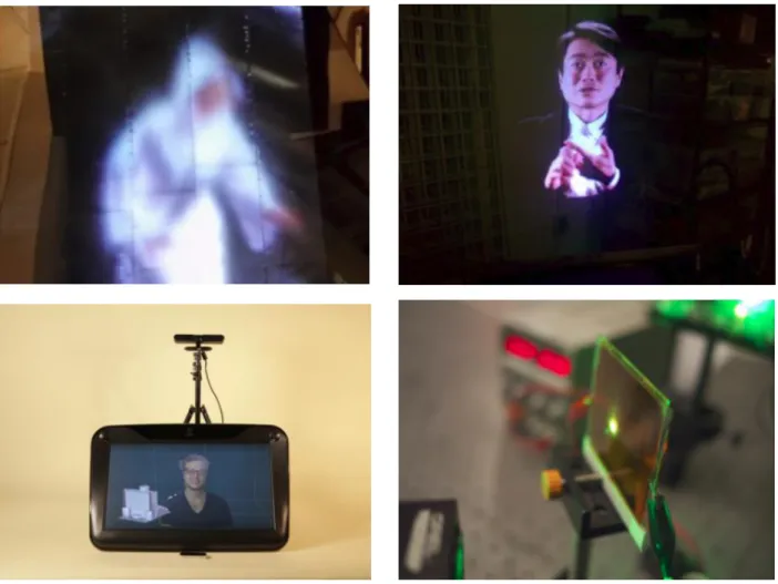
1-1: Examples of visual interfaces developed by our group. (top left) autostereoscopic aerial light-field display; (top right) 3D Telepresence Chair; (bottom left) Holosuite; (bottom right) Direct
fringe writing of computer generated holograms ... 20
1-2: Interior of Tesla Model S. According to the manufacturer’s website [10]: “The Model S 17-inch touchscreen controls most of the car's functions. Opening the all glass panoramic roof, customizing the automatic climate control, and changing the radio station all happen with a swipe or a touch. The touchscreen, digital instrument cluster, and steering wheel controls seamlessly integrate media, navigation, communications, cabin controls and vehicle data.” ... 23
2-1: Tactile belt from [13] ... 32
2-2: Vibrotactile vest by Eagleman and Novich [14] ... 33
2-3: Examples of tactile displays based on dynamic pin arrays. Images from [16], [17], and [18], respectively ... 33
2-4: CyberGrasp by CyberGlove Systems LLC [19] ... 34
2-5: Gravity Grabber [20] – prototype (left) and sample use case (right). When a user is holding an empty glass in the real world, they can perceive mass increase as virtual water is poured into the glass... 34
2-6: Wearable 3-DoF haptic interface from [12]. The prototype shown is worn on the index finger ... 35
2-7: Images of GROPE haptic display system (left) [22] and PHANToM haptic interface (right) [23] ... 37
2-8: Images of various grounded kinesthetic feedback devices. (left) Phantom® Premium™ [25], (center) CyberForce [26], (right) DLR Bimanual Haptic Device [27] ... 37
2-9: Image from [28] contrasting wearable haptic devices (a) based on mechanical actuation and (b) based on EMS... 38
2-10: Images of (a) FEELEX [33], (b) Lumen [34], and (c) Gemotion [35] - interactive shape displays ... 40
2-11: Shape displays by the MIT Media Lab’s Tangible Media Group. From left to right: Relief [37], inFORM [40], transFORM [41] ... 41
2-12: The Sensorama machine. Image from Wikipedia ... 42
2-13: Haptic feedback system from [55], featuring 100 air-jet nozzles ... 43
10
2-15: Images of the Ultrahaptics system [58-63]. The image on the left shows the early research
prototype, and the one on the right shows the current commercial product ... 44
2-16: (a) The HaptoMime system and (b) a diagram of its mechanical construction [64] ... 45
2-17: (left) Early prototype of the HORN system and (right) a diagram of its mechanical construction [66] ... 46
2-18: Photo of HaptoClone [68] ... 46
2-19: The AirWave system by Microsoft Research [72] ... 48
2-20: The Aireal system by Disney Research [49] ... 49
3-1: General design concept for AirTap. A haptic feedback frame featuring multiple vortex-ring generating apertures (left-side) that can be seamlessly mounted and integrated with an existing stereoscopic display such as zSpaceTM (right side) or another kind of display... 55
3-2: Prototype of the AirTap system. A user is seen grabbing a virtual block. The generators are all following the user’s hand and whenever the hand comes in contact with one of the objects, the appropriate generator fires a vortex ring which the user feels as a tap ... 57
3-3: Signal-flow block diagram representation of the AirTap system ... 57
3-4: Component representation of our current prototype. Each node represents an assembly or an abstract component, and its children are the constituent elements of that component. The value in parentheses denotes the number of children the parent node has, not the total number of those components in the system ... 58
4-1: Sequence of photographs from [76] showing the formation of a laminar vortex ring and its subsequent development. Reynolds number is about 1500. Note the formation of an azimuthal instability and the resultant formation of a turbulent vortex ring in (e) and (f) respectively ... 68
4-2: Examples of a tube-based generator (left), and two orifice-based generators (middle and right) ... 69
4-3: Cross sectional view of a piston-actuated cylindrical vortex-ring generator with orifice opening ... 71
5-1: Conceptual image of AirTap vortex-ring generator ... 77
5-2: Vortex ring generators by Microsoft Research (Left) and by Disney Research (Right) ... 78
5-3: Prototype 1. Air-vortex-ring generator based on single-chamber with multiple apertures design approach ... 80
5-4: Prototype 2. Piston-based vortex-ring generator ... 82
5-5: Prototype 4. A fixed cylindrical external electromagnet (left) that houses an internal electromagnet (right) ... 83
11
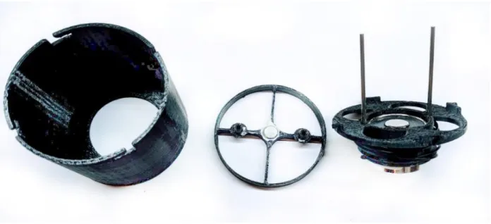
5-6: Prototype 5. A fixed cylindrical electromagnet (left) that houses a permanent-magnet-based piston (right) ... 83 5-7: Prototype 6. A housing (left), a permanent magnet-based piston (center), and base (right)
containing a commercial electromagnet and two stainless steel sliding rods for the piston .. 84 5-8: A piston cylinder set from Airpot ® (left), and the vortex-ring generator we built based on it
(right) ... 85 5-9: Apparatus for measuring the actuation time and actuation delay of the generator. It consists
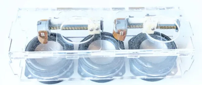
of a relay board, an Arduino board, a photointerrupter, and a 3D printed mounting cap ... 86 5-10: CAD Models of vortex generator chamber, assembled generator with transducers and nozzle viewed from the front and from the back ... 88 5-11: PCB on back side of the vortex generator ... 89 5-12: CAD Model of vortex generator mounting module, and a generator chamber positioned in the appropriate mounting location ... 89 5-13: Vortex Generator and Mount Assembly. The images on the left show a side view of the
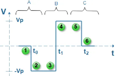
assembly when the generator is at 90-degree and 0-degree position, respectively. The right-side images show the corresponding views from the top at the same two positions ... 90 6-1: Basic actuation signal for each subwoofer of a toroidal vortex generator. The signal should
be applied simultaneously to all subwoofers of the generator ... 96 6-2: FET-based H-Bridge implementation. The blue line indicates the path of current flow through
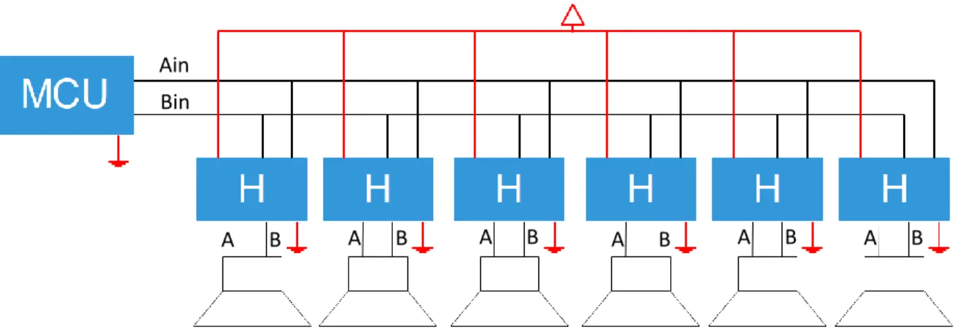
the load at the center for different scenarios depending on which transistors are on and which are off ... 98 6-3: Block diagram for a simple H-Bridge based approach to driving a toroidal vortex generator
with six subwoofer transducers ... 98 6-4: The main component types of our actuation driver are one MCP4725 DAC with breakout
board (left), and three MAX9744 dual Class D stereo amplifier boards (right) – both made by Adafruit Industries ... 100 6-5: Modified version of the MAX8744 Class D dual amplifier board. All modifications made to the
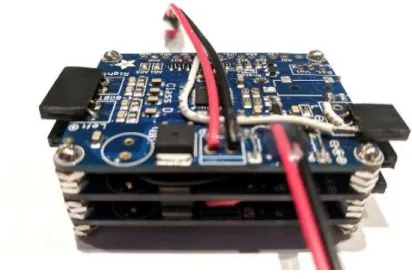
board are indicated by the labels. Each of our amplifier boards had to be modified exactly as shown in this figure ... 101 6-6: TriAmp consisting of three MAX8744 Class D amplifier boards modified according to our
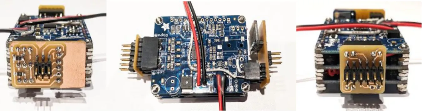
needs and sandwiched together ... 102 6-7: View of the TriAmp with the input-side and output-side vertically-mounted boards attached.
The left image shows the input-side board. The DAC is soldered behind the board and is visible when viewed from the top, as shown on the middle image. The right image shows the output-side board which rearranges the 12 amplifier outputs into a checkerboard pattern and channels them to a 2x6 pin IDC header ... 103
12
6-8: Block diagram of the complete actuation driver design based on the DAC + TriAmp configuration. All connections between the DAC, the three Amplifier boards, and
Microcontroller are captured in this diagram ... 105
6-9: Block diagram indicating how multiple drivers can be connected to the same microcontroller. Each additional driver requires only two additional microcontroller I/O pins ... 106
6-10: Actuation waveform candidates with different smoothing profiles ... 107
6-11: Simplest to generate actuation waveform that results in only a single audible pop during generator actuation ... 108
6-12: Block diagram of actuation driver based on the DRV8844 Quad Half-H-Bridge IC ... 110
6-13: Actuation driver board – front and back side – based on the block diagram from Figure 6-12 ... 111
6-14: Visual representation of fast current decay more and slow current decay mode ... 115
6-15: (left) ON resistance as a function of input voltage and temperature for the 74CBTLV3253 high speed mux/demux at Vcc = 3.3V and Isw = 64 mA. (right) I-V curve for the TLP241A photorelay. These graphs were obtained from the device datasheets of the 74CBTLV3253 and TLP241A, respectively ... 118
6-16: Simplified electrical model of the demultiplexer and the components connected to and powered by one of its output pins... 118
6-17: Images of the 6-channel 4-way signal splitter board – front and back side ... 119
6-18: Servo motor driver board (top) and corresponding PCB design file (bottom) ... 120
6-19: Teensy 3.5/3.6 breakout board for AirTap. The image on the left side shows the assembled board. The pinout for each connector is more clearly visible on the corresponding PCB design image on the right side ... 122
6-20: System-level block diagram of all electronics in AirTap ... 123
6-21: Representation of the geometric relationships between controller, hand, and generators .. 125
6-22: Bottom-side geometry ... 126
6-23: Top-side geometry ... 127
6-24: Left-side geometry ... 127
6-25: Right-side geometry ... 127
6-26: SolidWorks CAD model of the base platform. The real platform we built is identical to this model ... 130
6-27: Frame (left) and mounting assembly (right). These SolidWorks CAD models are identical to the real physical structures ... 131
13
6-28: Frame with mounting assembly. This SolidWorks CAD model is identical to the physical structure ... 132 6-29: Vortex-ring generator mount, whose bottom is designed for installation onto a 10-series
T-slotted aluminum profile ... 133 6-30: Vortex-ring generator mounts for the left and right sides of the monitor frame. Each side has
2 of the first type, 1 of the second type, and 1 of the third type of mounting assemblies .... 134 6-31: Image showing how the controller is mounted to the system ... 135 6-32: Views of the Leap Motion mounting assembly from three different angles ... 136 6-33: Image of the back of the monitor frame’s mounting assembly with all boards attached and all
cables connected ... 137 6-34: SolidWorks CAD models of the 3D-printed board holders. Top left: Holder for actuation driver
board. Top right: holder for servo motor driver board (2 per board). Bottom left: Holder for output signal splitter board (2 per board). Bottom right: Holder for Teensy 3.5/3.6 breakout board (4 per board) ... 138 6-35: The final two steps in completing the assembly of AirTap are to secure the frame with
mounting assembly onto the base platform (left-side image), and then remove the supports on the four corners and install the monitor (right-side image) ... 138 6-36: SolidWorks CAD model of the fully assembled AirTap system viewed from different angles
... 139 7-1: A demo user experience running on AirTap. When a user positions their hand in the volume
of interaction above the system, they see a representation of their hand in the virtual world ... 144 7-2: When a crate is touched, the user receives visual, auditory, and haptic feedback. The edges
of the crate glow and after a few hundred milliseconds the crate fades away and reappears at a different location ... 145 7-3: A hand whose fingers are parallel to the palm and touching each other cannot be detected
by Leap Motion. For a successful initial detection, the fingers must be spread apart or slightly bent ... 147 7-4: An early-state development version of a bubble-popping interactive experience for AirTap
14
List of Tables
5-1: Bill of materials necessary for building a complete air-vortex-ring generator and its mounting
assembly. The subwoofers and servo motor constitute 70% of the cost ... 91
6-1: Bill of Materials for the DAC + TriAmp based actuation driver ... 106
6-2: Bill of Materials for actuation driver board based on the DRV8844 Quad Half-H-Bridge IC ... 112
6-3: Table from the datasheet of DRV8844 Quad Half-H-Bridge, showing the different modes of operation of the device under PWM control ... 114
6-4: Bill of materials for an output signal 4-way splitter board ... 120
6-5: Bill of materials for a servo driver board ... 121
6-6: Bill of materials for Teensy 3.5/3.6 breakout board for AirTap ... 122
6-7: Bill of materials for the current Base Platform of AirTap ... 131
6-8: Bill of materials for frame with mounting assembly ... 133
6-9: Bill of materials for AirTap ... 139
7-1: Properties for the Camera, Controller, and Hand game objects that correspond to a geometrically appropriate visual experience, relative to a ground plane at the origin ... 146
15
Contents
1. Motivations and Goals ...19
1.1 Practical Necessity ...19
1.2 Contribution to a Currently Relevant Field ...24
1.3 Democratization and Proliferation of Haptic Feedback Interaction ...25
2. Background on Haptic Feedback Technologies ...31
2.1 Wearable Devices for Cutaneous and Kinesthetic Feedback ...32
2.2 Grounded Haptic Feedback Devices ...36
2.3 Wearable EMS Devices ...38
2.4 Active Surfaces ...39
2.5 Free-Space Haptic Feedback Devices ...41
2.5.1 Free-space haptics via Jets of Air ...42
2.5.2 Free-space Haptics via Focused Airborne Ultrasound ...43
2.5.3 Free-space haptics via Toroidal Air-Vortices ...47
2.5.4 Free-space haptics via Lasers ...49
2.6 Discussion of Our Preferred Approach to Haptics ...51
3. Introducing AirTap ...55
3.1 Design Concept ...55
3.2 Current Prototype ...57
3.3 AirTap as an Interactive Interface ...61
3.4 AirTap as a Research Tool ...61
3.3 AirTap as a Platform for Creative Expressions...62
4. Theory and Formation of Vortex Rings ...67
4.1 Vortex Ring Formation and Development ...67
4.2 Air-Vortex Rings Optimized for Haptic Feedback ...70
5. Toroidal Air-Vortex Generator Design ...77
5.1 Preliminary Concept Design ...77
5.2 Background ...78
5.3 Single Chamber with Multiple Apertures Prototype ...79
5.4 Prototyping and Evaluation of Various Actuation Approaches ...81
5.5 Prototype based on Electromagnet + Permanent Magnet Actuation ...85
5.6 A New Beginning, Renaissance ...87
16
5.6.2 Generator Mounting Assembly Design ...89
5.6.3 Bill of Materials for Generator with Mounting Assembly ...91
5.7 Discussion ...92
6. System Engineering and Design ...95
6.1 Actuation Electronics and Actuation Control ...95
6.1.1 Actuation via H-Bridge Driver with Basic Control ...97
6.1.2 Actuation via DAC + Class D Amplifiers ...99
6.1.3 Actuation via H-Bridge Driver employing PWM Control and Fast-Decay Mode ... 110
6.2 System Electronics and Control ... 116
6.2.1 Actuation Signal Splitter Boards ... 117
6.2.2 Servo Motor Driver Boards ... 120
6.2.3 Breakout Board for Teensy 3.5/3.6 ... 121
6.2.4 Electronics Integration ... 122
6.2.5 System Control... 123
6.3 Hand Tracking and Following ... 124
6.4 Mechanical Design and Construction ... 128
6.4.1 Design Considerations ... 129
6.4.2 Base Platform Design... 129
6.4.3 Frame and Mounting Assembly Design ... 131
6.4.4 Vortex-Ring Generator Mount Design ... 133
6.4.5 Leap Motion Controller Mount Design ... 134
6.4.6 Final System Assembly and Total Cost ... 136
7. Evaluation and Future Work ... 143
7.1 Interactive User Experience Design ... 144
7.2 User Observation and Feedback ... 146
7.3 Short-term Future Work ... 149
7.4 Medium-term Future Work ... 151
7.5 Long-term Future Work ... 152
17
1
19
C
HAPTER 1
Motivations and Goals
The work presented in this thesis was inspired by the convergence of several motivating factors and goas, which can be grouped into three distinct categories. First is motivation by practical necessity for the needs of the Object-Based Media group at the MIT Media Lab. The second motivating factor is to make a contribution to the emerging field of haptic feedback interaction, which is now becoming not only increasing more relevant and important, but also essential due to recent developments in AR, VR, and holographic technologies that are enabling high degree of realism and immersion in 3D visual experiences. Third, also the strongest personal motivation, is to democratize and liberate immersive haptic feedback interaction, which until now has only been accessible to and could only be experienced by people at the highest echelons of academia and industry. In this chapter, we elaborate on each of these three motivating factors.
1.1 Practical Necessity
The Object-Based Media group at the MIT Media Lab is famous for developing novel interactive interfaces including holographic displays and other 3D immersive displays and telepresence systems. One of the most recent examples is an autostereoscopic aerial light-field display [1] made by Dan Novy which is able to optically relay a life-size image of a person into free-space with 3D and motion parallax, and enabling gestural interfaces to be used to interact with the object. Another recent project is Holosuite [2] by Ermal Dreshaj, which is an end-to-end interactive 3D telepresence system that uses advanced 3D displays to seamlessly merge two 3D worlds, such that two distant individuals are merely separated by a metaphysical window. Through the use of gestural sensors, the Holosuite system enables users to share,
20
manipulate, and edit 3D objects in the common virtual space between them, thereby enabling remote collaboration. There are several earlier immersive 3D-display projects developed by our group, such as the 3D Telepresence Chair by Dan Novy [3], which uses the Pepper’s ghost effect to augment an office chair that appears to create a remote meeting participant; and some projects that are still ongoing such as Holovideo which is a true holographic display system [4,5,6,7].
The aforementioned projects are vastly different in the immersive visual and interactive experiences they create and in the underlying technologies and physics they use to enable those high-realism experiences. Nevertheless, analysis of the feedback received from the user studies conducted for those
Figure 1-1: Examples of visual interfaces developed by our group. (top left) autostereoscopic aerial light-field display; (top right) 3D Telepresence Chair; (bottom left) Holosuite; (bottom right) Direct fringe writing of
21
projects reveals that there is one reoccurring problem with them all. Users report that the realism and immersion is truly there initially, but it breaks down as soon as they reach in to touch the 3D object(s) when their hands simply go through the air without sensing anything. Moreover, for the case of projects where the user is expected to actively interact with and manipulate the 3D virtual objects using their bare hands, there is also a secondary problem. When pushing or grabbing a virtual object that cannot be felt, it is difficult for users to know when exactly their hands are in contact with the spatial boundaries of the virtual object [2, 3].
By turning to neuroscience and looking at the explanations it offers to phenomena involving conflicting sensory stimuli such as the rubber hand illusion and phantom limb syndrome [8], we can try constructing a similar explanation as to why realism might be perceived initially and then it disappears when the object cannot be touched. When only the visual sense is involved and when cues that indicate realism, such as motion parallax and occlusion, are present, the virtual object is perceived as a real physical object, since there is nothing to contradict that conclusion. But when one tries touching the virtual object and their hand goes through it unimpeded, the brain has a dilemma to resolve. The visual sense is saying that the object is there and the tactile sense is saying that it is not. In order to reconcile this conflict, the brain has to do one of two things. It has to either induce a physical sensation into the hand that matches the sensory input from vision, or it has to change the visual perception of the user so as to match the tactile stimulus. The latter of those is what happens of course, and consequently the user stops perceiving the realism. And even if they want to snap into that mode again, they can’t while the conflicting sensory input is still present. Only after the hand is removed from the space occupied by the object can the user start perceiving realism again.
The loss of realism during the interaction, and the inability to detect the spatial boundaries of a virtual 3D object, are two strong factors indicating that lack of haptic feedback also has ramifications beyond the sense of touch. Haptic feedback is needed not merely to add another sensory dimension to the experience, but also to improve the realism of visual and gestural experiences. In other words, visual, gestural, and haptic experience cannot be considered as independent from one another. They should be viewed as three
22
circles on a Venn diagram, which slightly overlap with one another; cutting any one of those out completely causes parts of the reaming two to also be cut.
The connection between holography and haptics has previously been explored at the Media Lab in the early 2000s [9], but a system that offers a viable solution to the problem is yet to be created. We thus need to develop a haptic feedback system that would solve the problems mentioned above. It needs to be one that could be applied to both the existing 3D visual interfaces in our group and to any future projects of that kind. Moreover, the solution has to be one that could easily integrate with any of the existing 3D display interfaces, without requiring modifications to those display interfaces. It also needs to be relatively slim, inexpensive, and portable if it were to be of real, practical value. For the same reason of practicality, it also needs to be mountable to the visual interface and not to the person using the interface. An approach to a solution that involves mounting something to the user’s body, such as a haptic glove, an exoskeleton, or the like was highly unappealing to us due to reasons of practicality and scalability, and also because such approaches tend to limit the dexterity of users. We elaborate much more extensively on the different approaches to haptic feedback in the next chapter.
Moreover, in the last 10 years we have witnessed an ironic backward trend in terms of haptic feedback interaction. Technological advances, rather than improving the richness of haptic information available, have actually left users with a significant deficiency of haptic feedback which previously used to be there. What we mean in particular is the proliferation of touchscreen-based devices and the widespread adoption of touchscreens as the default input controls for systems that previously used to be operated by physical controls. Physical controls give immediate indication to a user whether they have performed the desired action, without requiring the user to confirm visually that they have completed the task. Moreover, finding the location of a physical button or knob also does not require engagement of the visual sense, once the user has learned the approximate location of the control. Once a user positions their hand at the approximate location of the control, the physical shape and texture of the control itself and surroundings help the user find the exact location. Touch screens by contrast, in their current form, don’t offer any of those haptic guidance cues, and they always require visual inspection for both finding the location of the controls and
23
for making the desired changes. Knowledge of the approximate location of a control is not enough; exact location needs to be known as there are no haptic cues to help guide a user’s hand from an approximate location to the exact location. This is especially concerning for the case of automobiles or other heavy equipment (of which some now have only a touchscreen-based and speech-based control panel as shown on Figure 1-2) because an operator has to dedicate part of their visual bandwidth to operating the touchscreen – which could lead to distractions and potentially deadly consequence. Ironically, the MIT Media Lab, as a pioneer of touchscreen technology, is partly responsible for this unintended technological consequence, thus as members of the MIT Media Lab we find it our moral duty to work toward a possible technological solution, that maintains all the benefits of touchscreen based controls but does not have the aforementioned drawbacks.
Figure 1-2: Interior of Tesla Model S. According to the manufacturer’s website [10]: “The Model S 17-inch touchscreen controls most of the car's functions. Opening the all glass panoramic roof, customizing the
automatic climate control, and changing the radio station all happen with a swipe or a touch. The touchscreen, digital instrument cluster, and steering wheel controls seamlessly integrate media,
24
1.2 Contribution to a Currently Relevant Field
The second motivating factor for this work is to make a research contribution and a technological contribution to the field of haptic feedback interaction, which is becoming increasingly more important and more relevant at a time when technologies for immersive experiences are advancing at an unprecedented rate and are proliferating into the homes of thousands. The field of haptic feedback interaction has existed for several decades but the body of literature and the technologies that have been developed in that area are primitive by comparison to those in visual interaction. Haptic feedback devices are still in their infancy. We elaborate more extensively about the current state of research in this field in the chapter that follows.
Until recently, a true need for experiencing haptic sensation when interacting with virtual contents was not really there. Haptic feedback was mostly seen as an enhancement and as a feature that would be ‘nice to have’ but that was not all that necessary, largely because there were much more pressing visual challenges that needed to be addressed first. Until recently, visual interfaces have not been able to deliver a realistic 3D immersive experience. But this paradigm is shifting with the latest developments in and the proliferation of virtual and augment reality, 3D television, and true holographic displays. The convergence between new optical technologies, high computational power, advanced GPU capabilities, and photorealistic digitally-generated content, is for the first time enabling experiences with an unprecedented degree of visual realism and immersion, often referred to as presence – the feeling of ‘being there’, inside the virtual world. As a consequence of having reached a point where the challenges associated with visual realism are no longer a showstopper, and where numerous players from both industry and academia have entered the race for solving the remaining visual problems and are making progress every day, the perfect time to confront the final frontier to true immersion – namely the haptics problem – is now.
Over the past half-decade, we have seen a sweeping wave of innovation in visual immersion, and we are still riding that wave. The wave that comes right after it, we believe, will be in haptic (tactile and kinesthetic) feedback technologies that can integrate with the visual technologies to deliver rich visual and haptic immersion, and thereby provide the degree of true presence.
25
To satisfy this second motivating factor, our haptic feedback solution needed to be forward looking and be one that can be integrated with stationary 3D visual interfaces, while also having the potential for future integration with technologies such as VR and AR headsets or other relevant technologies that may arrive in the future.
1.3 Democratization and Proliferation of Haptic Feedback Interaction
The third motivating factor, and the one of highest personal importance, is universal democratization of haptic feedback technology. During the past several decades, numerous prototypes of tactile and kinesthetic feedback devices have been developed by researches in academia and industry. Devices ranging from haptic gloves and exoskeletons, to shape changing displays, to robotic devices delivering kinesthetic feedback, to mid-air tactile interfaces. Despite decades of research and development of haptic technologies, there has been very little proliferation and adoption of such systems. The devices that have reached general audiences are the absolute simplest and not so interesting ones - primarily vibrotactile stimulators like those used in smartphones and game controllers. The more exotic systems have largely remained as one-off prototypes confined within the walls of research institutions. General audiences are often completely unaware of the existence of those technologies, let alone having the opportunity to experience for themselves the affordances provided by these systems. The same applies even for technical audiences and for people who are genuinely interested in haptic technologies. Only individuals at the highest echelons of academia and industry have the opportunity to access and experience some, but still not all, of those technologies; and that is usually only during specific events such as conferences, exhibitions, and presentations where such systems are being demonstrated.
The aforementioned problems with access and proliferation exist for a number of reasons. Most haptic feedback devices are highly expensive, usually in the thousands or tens of thousands of dollars; complicated to build, requiring skills from several engineering disciplines to develop even a single device;
26
and their usefulness usually does not extend beyond a very specific narrow problem they address, thereby making the cost-benefit ratio unjustifiable. There is also a fourth reason which is stronger than all previous three, combined. Research prototypes are usually completely closed source, and the researchers and institutions who build such devices generally don’t share the technical details needed to replicate their prototypes, let alone any of the design files. Only a basic overview of the technical information required for a publication is what is being shared. As a consequence of this lack of technical details and lack of full openness, an individual wishing to replicate a research prototype is usually forced to start from scratch. They need to have skills in at least mechanical engineering, electrical engineering, design, and programming in order to try to reproduce a prototype published the HCI literature. This process of having to reinventing the wheel every time, is not only inefficient and wasteful, but also makes it impossible for anyone without an interdisciplinary set of skills, or an interdisciplinary team of engineers and designers, to recreate a research prototype even if they have the monetary and material resources. This closeness also limits progress in this area, because interested researchers cannot simply build on top of earlier works without having to first recreate those earlier artifacts and all supporting subsystems from scratch.
We wanted to build a system that is free from all of those problems. It had to be relatively inexpensive, easy to replicate, and have utility beyond just a narrowly defined task. It had to have an appealing cost-benefit ratio. We wanted our device to not be just another research prototype that shares the fate of isolation that nearly all other non-commercial haptic feedback devices share, but rather to defy this tradition. Our intent from the very start was to not only make the system fully open source, but also share the original design files, and additionally provide detailed descriptions for how to replicate the complete system and even expand upon it – after we have published this work. We wanted researchers and other interested individuals who come across this work to feel empowered to be able to replicate it with ease, expand upon it, or take in a completely different direction. We wanted this work to help accelerate the proliferation of haptic feedback technology by empowering people with and without technical skills to be able to experience the latest research in haptic feedback interaction, and thereby democratize and liberate haptic feedback technologies. That is why we chose to build not just a haptic feedback system but an entire
27
interactive interface platform where haptic feedback is simply one component of the system. Our goal was to create a complete platform for creative interactive expressions – for which designers, artists, and engineers can develop novel immersive experiences involving visual, auditory, gestural, and tactile interaction. By empowering people from all walks of life with a relatively inexpensive system that enables them to have the opportunity to create their own unique immersive experiences, and by providing them with the opportunity and knowledge to replicate the system itself, augment it, or make it even less costly, we are hoping to accelerate the proliferation of haptic feedback interaction and contribute to a future where such devices are just as commonplace as audio-visual interfaces are today. The two quotations that appear at the start of this thesis, by Mark Weiser and by Nicholas Negroponte, are a reflection of this longer term future vision of ours.
28
29
2
Background on Haptic Feedback
Technologies
31
C
HAPTER 2
Background on Haptic Feedback Technologies
While audio and visual output technologies have now reached a point where they can deliver an experience so rich and immersive, that it can be characterized as presence, the corresponding haptic feedback technologies are still in their infancy and largely incapable of delivering rich haptic information (kinesthetic and cutaneous), let alone the illusion of presence. In the case of visual interfaces, the basics of delivering rich visual content have been solved over half a century ago with the invention and proliferation of color television. By contrast, when it comes to the richness of content delivered by today’s commercial haptic interfaces, it is as if are still living in the era before black and white television. By this analogy, haptic feedback technologies on the market today are lagging by nearly a century compared to their visual counterparts. There is a clear need to meet the immersive capabilities of audio and visual output with equally immersive haptic experiences.
Considerable effort has been expanded to address this deficiency, and especially in the last decade, we have witnessed some exciting developments under research. In this chapter we provide a brief overview of the different approaches to haptic feedback interaction, discuss their advantages and drawbacks, and present a number of examples from each category. After an extensive search, we have not been able to find any up-to-date resource that provides an inclusive taxonomy of haptic feedback devices, so we attempt to make our own categorization below which is based on the categorization presented in [11], but we also include the additional categories of electrical muscle stimulating (EMS) devices and grounded kinesthetic feedback devices. This categorization is not meant to serve as an exhaustive taxonomy of haptic feedback interfaces, but primarily for giving the reader a flavor for the wide diversity of approaches to haptic feedback interaction in HCI applications.
32
2.1 Wearable Devices for Cutaneous and Kinesthetic Feedback
Tactile devices provide cutaneous feedback by stimulating the skin directly, usually by using miniature electromechanical actuators. The three main approaches to generating tactile feedback with wearables is through vibrations, local skin deformation using dynamic pins arrays, and the application of three-dimensional vector forces at different contact points [12].
Vibrotactile feedback is the most well-known approach to wearable haptics, which has been popular ever since the advent of mobile phones and game controllers. It has low complexity to build and low cost to implement, however, it also is very limiting in its ability to deliver any rich contact interaction about virtual or remote objects. Nevertheless, there are still many practical applications for vibrotactile feedback, and exciting new haptic technologies utilizing vibrotactile stimulus are still being developed - especially in the area of sensory augmentation / substitution as we discuss in the next two paragraphs.
Karcher et. al. [13] presented a tactile belt as a sensory augmentation device for the blind. The belt, shown in Figure 2-1, delivers directional information on the user’s skin by means of 30 vibrotactile actuators. There is a compass integrated into the device that senses
magnetic north. When switched on, the northernmost element starts vibrating, signaling to the wearer the direction of magnetic north. Evaluation results revealed that, not only was the device helpful in daily tasks that are complicated for the blind - such as keeping track of direction over longer distances or when taking shortcuts in familiar environment - but it also led to positive emotional impact in wearers and enhanced feeling of security.
More recently, Novich and Eagleman [14] demonstrated a wearable device in the form of a vest that encodes speech into vibrotactile information that users can sense on their backs. This is a sensory substitution device initially designed for deaf people that enables them to “hear” through their backs,
33 effectively substituting touch for hearing. An improved commercial version of the device was developed, called The VEST (Versatile Extra-Sensory Transducer) [15], which was marketed for applications of sensory augmentation including the ability to directly “feel” dynamic data streams such as stock market data and audience engagement based on Twitter feeds.
Another approach to providing haptic feedback with wearables is via dynamic pin arrays. Yang et. al. [16] developed a cutaneous display composed of a 6x5 pin-array that was able to display planar and Braille cell patterns to the fingertips. Pin-arrays are also employed in [17], where a solenoid, a permanent magnet, and an elastic spring were used to develop a miniature cutaneous module. Although this kind of display is very flexible and effective, it usually
employs a large number of actuators, compromising overall wearability and portability. The wearability problem was addressed by Sarakoglou et al. [18] with a compact 4x4 tactors array that was remotely actuated through a flexible tendon transmission. The portability problem, however, was not solved since a need for an external drive unit for the actuation system still remained.
Figure 2-2: Vibrotactile vest by Eagleman and Novich [14].
Figure 2-3: Examples of tactile displays based on dynamic pin arrays. Images from [16], [17], and [18], respectively.
34
A third approach to wearable haptics is achieved by applying three-dimensional force vectors at different points on the wearer’s body. Devices in this category are generally for kinesthetic feedback. They are typically grounded on one part of the body
(e.g. forearm) to provide feedback on another (e.g. fingers) by exerting localized forces that restrict the natural degrees of freedom of the body. For each component of the exerted force, a separate motor is generally required. A well-known example is CyberGrasp [19], as pictured on Figure 2-4. The mechanics of these devices are complex, and it is difficult to make them portable and inexpensive.
Devices with higher portability based on this approach have been proposed. Minamizawa et al. [20] presented Gravity Grabber, a wearable and portable ungrounded haptic display able to apply cutaneous forces to simulate weight sensations of virtual objects. The approach was based on the insight that cutaneous sensations make a reliable weight illusion, even when the kinesthetic information is absent. The device consisted of two motors and a belt able to deform the fingertip, as shown in Figure 2-5. When motors spin in opposite directions, the belt applies a force perpendicular to the user’s fingertip. If motors spin in the same direction, the belt applies a shear force to the skin.
Figure 2-4: CyberGrasp by CyberGlove Systems LLC [19].
Figure 2-5: Gravity Grabber [20] – prototype (left) and sample use case (right). When a user is holding an empty glass in the real world, they can perceive mass increase as virtual water is poured into the glass.
35
More recently, Prattichizzo et al. [12] presented a 3-degree-of-freedom (DoF) wearable haptic interface, Figure 2-6, capable of applying force vectors directly on the fingertips, by using a mobile platform that is grounded on the back of the finger in order to apply forces at the finger pad. The device is composed of one static platform that supports three motors, and one mobile platform that is in charge of applying the requested force to the finger pad.
One of the main advantages of portable, wearable haptic feedback devices in HCI applications is that they are not limited to a constrained workspace. They allow users to move and perceive haptic feedback around a very large space. An example scenario at which wearable haptic devices excel when it comes to virtual object perception, is the case where the scale of the object or of the environment of interest is very large, such as room scale.
Wearable haptics have many disadvantages, however. Restrictions to movement, external perception, and dexterity – are some of the primary limitations. When wearing haptic devices, users’ hands are often restricted and cannot be used effectively for everyday tasks unrelated to the particular virtual experience. We view haptic wearables as devices that give users freedom to feel virtual objects at the expense of feeling the texture of physical objects. In other words, most haptic wearables are not augmenting users new abilities but simply transforming their ability of feeling reality into an ability to feel virtuality at reality’s expense. Wearability also introduces power limitations. Users must either wear a power source on
their bodies or be tethered to one with cables, which compromises devise usability. Another very important limitation is that users cannot simply walk up to a virtual object and touch it as they would a real one. Having to put a device on their hands makes the experience of touching a virtual object not genuine, because the wearable device is what is contacting the virtual object and not the hand directly. Or in terms of the esoteric academic terminology of the MIT Media Lab, the magic of the experience of feeling a virtual object is lost. (Anyone out there reading this thesis? If you are, let me know at alims at media.mit.edu.)
Figure 2-6: Wearable 3-DoF haptic interface from [12]. The prototype shown is worn on the index finger.
36
Because of the aforementioned limitations and disadvantages, we find the wearable approach to haptic feedback interaction as an unsatisfactory solution for the practical needs of our research group. Moreover, it also falls short in meeting some of our other goals from in Chapter 1. Specifically, in terms of impact, traditional wearables have been extensively studied for decades and many of the research questions in that space have been answered and the solutions well understood. Another publication or two in that space would constitute a very limited contribution.
2.2 Grounded Haptic Feedback Devices
Force-reflecting haptic feedback devices that are mounted to a table, the ground, or some other object that isn’t easily movable, are referred to as grounded. These should not be confused with body-grounded devices, which in our classification fall under the wearable haptic devices. From a physics standpoint, grounded devices are capable of more accurately simulating contact forces that stem from grounded sources (e.g. walls, tables) compared to body-grounded devices. That’s because in the case of body-grounding, the force applied to one part of the body (e.g. finger) is balanced out by an equal and opposite force applied to the grounding site (e.g. forearm), always resulting in a null net applied force. By contrast, with grounded devices, the grounding surface is external to the user and the net applied force on the user’s body is nonzero [21].
Grounded haptic feedback devices for virtual environment applications first began to be explored in the earlier 1990s, with GROPE by Brooks et al., 1990, being one of the earliest prototypes [22]. Another project from the same year was the MIT Sandpaper by Minsky et al, a 3-DoF joystick that was capable of displaying virtual textures. In 1994, the MIT Artificial Intelligence Laboratory built the PHANToM which could convey the presence of virtual objects [23]. More information about these and other of the earliest grounded haptic feedback devices can be found in [24].
37
A more recent example of a grounded haptic feedback interface is the Phantom® Premium™ which includes a passive stylus and thimble gimbal and provides 3-DoF positional sensing and 3-DoF force feedback [25]. CyberForce consists of a CyberGrasp exoskeleton system attached to a robotic armature offering a workspace of 30.5cm x 30.5cm [26]. One of the most expensive haptic systems of this category is the DLR Bimanual Haptic Device, which is composed of two DLR/KUKA lightweight robot arms mounted behind the user to provide 6-DoF haptic feedback to both hands of a user [27].
Figure 2-7: Images of GROPE haptic display system (left) [22] and PHANToM haptic interface (right) [23].
Figure 2-8: Images of various grounded kinesthetic feedback devices. (left) Phantom® Premium™ [25], (center) CyberForce [26], (right) DLR Bimanual Haptic Device [27].
38
The main limitations of grounded haptic feedback devices are their mechanical complexity and high cost, often in the tens of thousands of dollars. Moreover, these devices share most the same drawbacks as the wearable haptic feedback devices discussed in the previous section.
2.3 Wearable EMS Devices
Electrical Muscle Stimulation (EMS) is one of the latest approaches to haptic feedback in human-computer interaction (HCI). EMS devices use a signal generator and electrodes attached to the user’s skin to send electrical impulses to one’s muscles. This causes the muscles to contract involuntarily, thereby letting the device actuate the user’s limbs [28]. Although still wearable, the EMS approach to haptics is very different from traditional wearable haptic feedback devices. Unlike an exoskeleton,
which adds mechanical components to one’s limbs, EMS effectively hijacks the body’s own skeleton and muscles. There is no need for bulky hardware and massive battery packs to drive the mechanical actuators. With EMS, only a small battery is needed for providing an electrical stimulus. The body’s own stored energy is then used for the motion of the stimulated limb. Moreover, the stimulator pads are very thin and are placed on the forearm, therefore not obstructing the user’s hands or arms. Furthermore, unlike an exoskeleton, whose range of motion is limited by the specifications of the actuators it is made of, EMS allows the full range of motion that a limb naturally has. These characteristics make EMS several times cheaper and more practical than an exoskeleton approach to haptics.
Figure 2-9: Image from [28] contrasting wearable haptic devices (a) based on mechanical actuation
39
The phenomenon itself has been known for centuries, ever since Luigi Galvani found out that by applying electric current to the leg of a dead frog it makes it twitch, which he then used to make corpses of executed prisoners ‘come to life’, which became the inspiration for Mary Shelley’s “Frankenstein”. EMS was first used in living humans in the 1960’s for rehabilitation medicine to regenerate lost motor functions [28]. But only in the last few years have researchers begun using EMS to create interactive experiences such as: teaching users how to play a musical instrument by controlling another person’s hand remotely [29], navigation during walking [30], and increasing realism and immersion in virtual experiences [31].
Although EMS is one the most promising technologies for kinesthetic haptic feedback currently in existence, it falls short when it comes to tactile or cutaneous feedback. Researchers building interactive systems based on EMS are also using traditional wearable haptic feedback devices when they want the user experience to offer cutaneous feedback in addition to the kinesthetic feedback provided by EMS [32].
Since we are primarily seeking a solution for delivering tactile rather than kinesthetic perception, EMS is therefore not a suitable technology for satisfying our practical goals from Chapter 1. The fact that it is still a wearable approach also makes it unappealing to us for the reasons specified in Section 2.1. Moreover, a tool will not become part of daily life if it’s seen as an encumbrance. Hence, our goal is a fully untethered system.
2.4 Active Surfaces
Active surfaces are devices that construct a tangible, physical representation of the properties of a virtual or remote object. Active surfaces can dynamically change their shape, mechanical properties, and/or texture, and they are able to sense and respond to touch by people or other objects. Unlike wearable haptic devices which try to create the illusion of a boundary through minimal feedback, an active surface by contrast tries to recreate the shape of the actual object being represented. Such devices aim to provide
40
distributed tactile information to the skin, while also communicating shape to the whole hand. Thus they simultaneously exhibit both cutaneous and kinesthetic characteristics.
One subcategory of active surfaces is shape displays, which modulate height fields by mechanically actuated pin arrays. They change their surface topology to provide a haptic 2.5D experience in addition to graphical output. FEELEX [33] is a classic example where 36 motorized pins modulate the shape of a soft surface onto which graphics are projected. Another example is Lumen by Poupyrev et. al. [34], which utilizes shape memory alloy to actuate pixels on a tabletop display. It is driven by a 13 x 13 nitinol actuator array. Graphic overlay is provided by lighting each actuated pin with a monochrome LED. Gemotion Screen by Niiyama and Kawaguchi [35] utilizes pneumatically actuated flexible fabric screens with front projected graphics to display organic art. Photonastic Surface by Oguchi et al. proposes a novel mechanism to address individual actuators of 2.5D shape displays using projected light [36].
More recently, a variety of shape displays have been built by the MIT Media Lab. Relief, developed by Leithinger [37], was the first of a series of prototypes. It was very similar to FEELEX, except that it used 120 motorized pins instead of 36, and it was built using open-source hardware and software tools. This was soon followed by a prototype that enabled direct gestural manipulation of the rendered surface [38]. In 2013, Follmer and Leithinger presented the next prototype, inFORM, which provides for variable stiffness
Figure 2-10: Images of (a) FEELEX [33], (b) Lumen [34], and (c) Gemotion [35] - interactive shape displays.
41
rendering and real-time user input through direct touch and tangible interaction [39]. A year later, they showed how the system could be used for physical telepresence of both people and objects, enabling computer mediated remote collaboration [40]. The most recent shape display from the Media Lab’s Tangible Media Group is transFORM which a much larger version of inFORM, enabling additional applications while also serving as a platform for creative interactive expressions [41].
Another approach to active surfaces is deformable crusts, which can be achieved through a variety of actuation technologies, including rigid linkages [42] and particle jamming [43]. The particle jamming approach to deformable crusts enables continuous surface control and higher resolution compared to the rigid linkages approach [11]. Additional approaches to developing active surfaces include electromagnetic levitation [44] and inflatables [45, 46].
2.5 Free-Space Haptic Feedback Devices
Recent advances in computer vision and hand tracking algorithms have helped bring into the marketplace novel devices, such as Microsoft Kinect and Leap Motion, that allow developers and researchers to build mid-air gestural interfaces. Touchless sensing is a key enabler for supporting user
Figure 2-11: Shape displays by the MIT Media Lab’s Tangible Media Group. From left to right: Relief [37], inFORM [40], transFORM [41].
42
interaction in mid-air [47]. In the last decade, we have also witnessed the emergence of technologies capable of delivering localized force feedback at a distance, without requiring the user’s skin to be in contact with any hardware in order to experience haptic sensation. An ultrasonic approach was demonstrated by Iwamoto et. al. [48] in 2008 and an air-vortex approach by Sodhi et. al. [49] in 2013. Even more recently, other free-space haptic feedback systems have also been proposed involving the use of lasers to directly stimulate mechanoreceptors on the hand [50, 51]. The convergence of optical tracking technologies with free-space haptic feedback technologies is enabling a fundamental shift in how we interact with computers and devices.
2.5.1 Free-space haptics via Jets of Air
As early as the late 1950’s air has been explored as a haptic feedback medium in HCI applications. Sensorama was one of the earliest projects [52] – an immersive multimodal system that integrated a stereoscopic motion picture display, aromatic smell, stereo sound, and wind blowing into the user’s face. A photo of the Sensorama machine is shown on Figure 2-12. In the decades that followed, similar air-blowing techniques have been used in entertainment venues and theme parks. The two main drawbacks of the blowing air-jet technique are low resolution and short range [49]. Classic air-jets have a haptic feedback range of less than 30 cm [53]. Only with
significant increases in power and jet-diameter can the range be increased, which reduces the resolution and also makes building such a system impractical and expensive. The fundamental flaw of air-jets from the HCI perspective is that they cannot maintain focus and start dissipating almost immediately after the air
Figure 2-12: The Sensorama machine. Image from Wikipedia.
43 leaves the nozzle. More recent interactive systems utilizing air-jet haptics have been demonstrated in 2002 [54] and 2005 [55], but in both cases the users reported that the corresponding virtual objects felt soft to the touch. Even more recently in 2013, an Air-Jet display was developed for providing haptic feedback for lump (tumor) perception during remote surgery [55].
2.5.2 Free-space Haptics via Focused Airborne Ultrasound
In 2008, Iwamoto et. al. [48] demonstrated a tactile display using 40KHz focused ultrasound modulated at ~200Hz to deliver tactile sensations in mid-air. The device, pictured in Figure 2-14, consisted of a 2D array of ultrasonic transducers which were driven using a phased array focusing technique. 40KHz ultrasound is non-penetrative, therefore more than 99.9% of the incident acoustic waves are reflected by the user’s skin, applying pressure to the skin
in the process, which provides perceptible tactile sensation. By modulating the ultrasound at low frequency, in addition to pressure-stimulus the mechanoreceptors also experience vibrational stimulus. Human skin is most sensitive to vibratory stimuli with frequency in the vicinity of 100Hz to several hundred Hz. By combining the pressure stimulus with vibrational stimulus, the perceived intensity of the tactile sensation increases. Moreover, different modulation frequencies and modulation schemes result in different vibrational stimulus, which results in different tactile perceptions. [48, 56, 57]
Ultrasound-based cutaneous stimulus was an exciting innovation that seemed very promising for the haptics problem in HCI. It offers relatively high resolution of approximately one square centimeter,
Figure 2-14: Ultrasonic tactile display by Iwamoto et. al. [48].
Figure 2-13: Haptic feedback system from [55], featuring 100 air-jet nozzles.
44
uses low power compared to other approaches to haptics, is relatively compact in terms of volume, the focal point is programmatically steerable, and different modulations schemes offer the possibility of experiencing different kinds of tactile perceptions. As a consequence, during the past decade many research groups have expressed interest in the technology and developed numerous prototype systems based upon it.
Alexander et al. in 2011 proposed an ultrasound-based tactile feedback method named Ultrahaptics [58]. Between 2011 and 2014 they developed several generations of the Ultrahaptics system including providing different textural sensations through frequency modulation, generating multiple focal points to create the illusion of surfaces and edges, developing better focusing algorithms that cancel secondary constructive interference peaks, and integrating an ultrasonic tactile display with a visual screen to deliver multisensory interactive experiences [59, 60, 61]. In terms of commutations and HCI design opportunities, Obrist et al. showed that the tactile sensation generated by Ultrahaptics technology can be verbalized [62], which implies that noncontact tactile sensation can convey certain mental images. In addition, their group extended their work to showing that emotions can be communicable via midair tactile sensation by controlling the location on the palm, direction of the movements, frequency, intensity, and duration of the ultrasonic focal point [63].
Figure 2-15: Images of the Ultrahaptics system [58-63]. The image on the left shows the early research prototype, and the one on the right shows the current commercial product.
45
Monnai et. al. has expanded the airborne ultrasound tactile display technology to “touchable holography” - floating touch panels - with a system named HaptoMime [64], and to touchable 3D tactile images – a project named HORN [65, 66, 67]. HaptoMime enabled users to interact with a 2D floating image by using one finger. This was interactive but two-dimensional. By contrast, HORN reconstructed a 3D tactile image but it was not fully interactive. In the demos of HORN, the displayed haptic object was a static energy concentrated distribution. Users could feel a 3D shape by their own hand motions around the static distribution. The displayed visual image was 2D. Makino et. al. [68] in 2015 proposed HaptoClone – a visual and tactile telepresence system for both people and objects. Two people can communicate using cloned images with tactile feedback. Each side can see and touch the other side’s volumetric image in real time.
46
Despite its many advantages, the airborne ultrasound approach to haptics has some significant limitations. The perceived tactile stimulus is very week. In the case of HaptoClone, which is the most sophisticated and the one with more ultrasonic transducers (996) than all other such systems, the perceived haptic sensation is still barely noticeable. According to the researchers [68], “In our system, however, the maximum force is small, and only a gentle and soft touch is produced.” In other prototypes that use smaller
Figure 2-18: Photo of HaptoClone [68].
Figure 2-17: (left) Early prototype of the HORN system and (right) a diagram of its mechanical construction [66].
47
number transducers the sensation is even more faint, and some users with less sensitive skin are unable to feel it at all. The other main drawback is the range, which is limited to only ~30cm above the surface of the tactile display. The range and the acoustic pressure are both functions of the number of transducers used. Only with a significant increase in the number of ultrasonic transducers can the sensation and/or range be increased, which would make the display impractical due to its surface area. A display with 249 small ultrasonic transducers occupies an area of 20cm x 15cm, and that is already impractical in many applications. Because of the large areal footprint, an ultrasonic display cannot be easily integrated with existing volumetric and 3D displays. Exactly the opposite is what has been done previously by researchers – they had to make the visual component fit around the ultrasonic display, not the other way around. Related to this is the fact that the volume of haptic feedback interaction is determined by the surface area of the ultrasonic display, further limiting the usefulness and practicality of this approach.
2.5.3 Free-space haptics via Toroidal Air-Vortices
A more recently invented approach to mid-air haptics in HCI applications is through the use of air-vortex rings, also known as toroidal air-vortices, which can remain focused for several meters and impart highly perceptible tactile sensation – unlike jets of air that don’t maintain directionality and dissipate quickly. Air-vortex rings have been known for centuries, and have been studied more intensively in the last several decades. They have found many practical applications ranging from olfactory stimulus delivery [69], to putting out fires [70], to uses as a non-lethal military weapon [71]. But it wasn’t until 2013 when they were first used for localized haptic feedback delivery in interactive systems.
Gupta et. al. [72] investigated for a first time in 2013 how toroidal vortices can be optimized for delivering strong localized haptic feedback. Prior to that work, the relationship between perceived force and vortex formation was not formalized in the literature. Their group demonstrated an air-vortex generator named AirWave, which could deliver vortex rings with a range of up to 2.5m and a target accuracy of 10cm.
![Figure 2-3: Examples of tactile displays based on dynamic pin arrays. Images from [16], [17], and [18], respectively](https://thumb-eu.123doks.com/thumbv2/123doknet/13916623.449426/33.918.429.812.604.967/figure-examples-tactile-displays-dynamic-arrays-images-respectively.webp)
![Figure 2-11: Shape displays by the MIT Media Lab’s Tangible Media Group. From left to right: Relief [37], inFORM [40], transFORM [41]](https://thumb-eu.123doks.com/thumbv2/123doknet/13916623.449426/41.918.107.812.333.529/figure-shape-displays-media-tangible-media-relief-transform.webp)