Development and Validation of a Terrain
Adaptive Prosthesis Control System
by
Roman Stolyarov MASSACHUSETTS INSTITUTEOF TEPHNOLOGY B.S. Computer Science, Mathematics, Biology
Southern Methodist University, 2014
FEB
19 20?0
LIBRARIES
ARCHIVES
Submitted to the Harvard-MIT Program in Health Sciences and Technology, in partial fulfillment of the requirements for the degree of
Doctor of Philosophy at the
The author hereby grants to M1T perrnission to Massachusetts Institute of Technology reproduce and to distribute putit-!y papexr antd February 2020 6tectronic copies of this thesis document ia,
whole or
in part in
any medium
now known
a
@2019 Roman Stolyarov. All rights reserved.
Signature redacted
Signature of author:
Harvard/MIT Division of Health Sciences and Technology September 20, 2019
Signature redacted
Certified by:
Hugh Herr Professor of Media Arts and Sciences Thesis Supervisor
Signature redacted
Accepted by:
Emery N. Brown, MD, PhD Director of Harvard-MIT Program in Health Sciences and Technology Professor of Computational Neuroscience and Health Sciences and Technology
Development and Validation of a Terrain
Adaptive Prosthesis Control System
by
Roman Stolyarov
Submitted to the Harvard-MIT Program in Health Sciences and Technology on September 20, 2019 in Partial Fulfillment of the Requirements for the Degree of Doctor of Philosophy
in Medical Engineering and Medical Physics ABSTRACT
Wearable lower limb robotic devices have great potential in addressing gait pathologies through assistive or rehabilitative means. In the case of amputation, powered prostheses can be used to recapitulate biological walking, improving mobility and diminishing amputation-associated comorbidity. In the case of intact limb pathologies such as weakness or paralysis, powered exoskeletons can be used for similar goals. A major challenge in developing these technologies lies in their control, whose aim is to improve gait dynamics across a variety of walking conditions. Perhaps the most significant determinant of gait dynamics is ground terrain: numerous studies have shown that walking on level ground, inclines, or stairs signif-icantly affects leg dynamics. Additionally, it has been shown that abnormal or asymmetrical gait across any of these conditions causes comorbidities secondary to gait pathology, includ-ing back pain, increased fatigue, and in the case of amputation, osteoarthritis of joints in the unaffected limb. Motivated by the desire to normalize gait mechanics across a variety of conditions, the principle aim of this work is to develop an automatically terrain adap-tive control system for lower limb robotic devices, wherein the control system anticipates transitions in walking tasks independently of external devices and switches to corresponding control policies. In particular, we focus on development and validation of such a control system in a below-knee prosthesis. The final result of this work is a method to automatically measure and accurately predict terrain geometry in a lower limb robotic device as a person is walking, along with a terrain-adaptive tunable control model that can successfully improve gait dynamics across multiple walking conditions.
Thesis Supervisor: Hugh Herr
ACKNOWLEDGEMENTS
First and foremost, I would like to acknowledge my advisor, Professor Hugh Herr. Hugh, thank you for entrusting me with helping to advance your vision of curing disability. You always struck a balance between providing mentorship and autonomy, such that over the last five years I grew the confidence to make my own judgements and decisions about technology development. I will forever be grateful to you for offering me this opportunity.
I would also like to thank the remainder of my thesis committee, including Professors Leia Stirling and Nicholas Roy. Leia, thank you for always being willing to listen, and for encouraging me to pursue and see the advantage of simpler solutions even though those solutions are not necessarily described by buzzwords. Nick, thank you for always quickly and incisively getting to the bottom of my work and identifying critical improvements.
To Biomech, you have changed significantly over the years but have always felt like a family. There are too many of you to thank individually, but I would like to give special thanks to Drs. Michael Eilenberg, Oliver Kannape, and Tyler Clites, and to Matthew Carney and Mike Nawrot. Michael and Olli, thank you for helping me get up on my feet in the lab. Tyler, thank you for introducing me to the lab, and for the many conversations we would have when you would come to my office to talk about our feelings. Matt, thank you for teaching me so much about mechatronics and for inviting me to help develop the TF8 system. Finally, Mike, thank you for taking so much of your own time to help me with my experiments.
To my parents: you have given me so much love over my life, and have always encouraged me and been my biggest supporters. I am extremely lucky to have parents like you, who not only risked everything by moving to the United States from the Soviet Union as working adults with two children, but also decided to give me new life shortly thereafter, even before you had fully settled in to your new country. Thank you for giving me the gift of fulfilling an American life and American dream, and thank you for being my best friends in the world!
To Arielle: Thank you for always supporting me, for dealing with my need to work on my thesis and worries about not finishing. Thank you for always assuring me that things are going to work out great. And thank you for always unconditionally being there, for always doing everything you possibly can to help, for showing me so much love, every single day.
To my brothers Yura and Sasha: I have always and continue to look up to both of you. Yura, all of those programming challenges you gave me when I was a kid kick-started my passion for engineering and rigorously solving problems. Sasha, you showed me what graduate school was all about, and it was you who originally inspired me to apply.
To the rest of my warm, loving, close-knit, awesome family, thank you for being my Best-Fam! Arik, Elik, Layla, Rose, Ella, thank you for the privilege of being your unkie monkey. Gala and Lena, thank you for being such awesome sisters(-in-law). To my grandparents Ika, Voka, Rosa and Garik, thank you for always believing in me and for the many, many warm conversations and moments together. You will always be in my memories and in my heart.
Finally, thank you to my amazing friends both from MIT and from my previous life in Dallas. Jesse, Brandon, Erica, and Richard F., thank you for enriching my life so much while at MIT. Richard R., Oscar, Josh, and Zia, thank you for maintaining our long distance friendship, for inviting me to SMU games, and for staying in contact now for five years since I left Dallas. I hope that we continue our friendships forever!
Contents
1 Introduction 10
1.1 Overview and specific aims . . . . 10
1.2 Background and motivation . . . . 11
1.2.1 Prevalence of leg amputation and prosthesis use . . . . 11
1.2.2 Comorbidities associated with long term prosthesis use . . . . 11
1.2.3 Lower limb prostheses . . . . 13
1.2.4 Joint proprioception and biological limb control . . . . 13
1.2.5 Main challenge of prosthetic control . . . . 13
1.2.6 Intrinsic control . . . . 14
2 Offline terrain classification analysis using only intrinsic sensors 18 2.1 A bstract . . . . 18
2.2 Motivation . . . . 18
2.3 M ethods . . . . 19
2.3.1 Data collection . . . . 19
2.3.2 Offline Classification Analysis . . . . 21
2.4 R esults . . . . 25
2.4.1 Generated stride list . . . . 25
2.4.2 Translational signals . . . . 26
2.4.3 Task prediction analysis with fixed cutoff . . . . 26
2.4.4 Task prediction analysis with variable cutoff . . . . 28
2.4.5 Feature reduction . . . . 29
2.5 D iscussion . . . . 29
2.5.1 Summary . . . . 29
2.5.2 Advantages of the proposed method . . . . 30
2.5.3 Potential improvements and limitations . . . . 31
3 Accurate Heuristic Terrain Prediction in Powered Lower-Limb Prostheses Using Intrinsic Sensors 32 3.1 Introduction . . . . 32 3.2 A bstract . . . . 32 3.3 Motivation . . . . 33 3.4 M ethods . . . . 35 3.4.1 Overview . . . . 35 3.4.2 Data collection . . . . 35
3.4.3 Offline processing . . . . 3.5 R esults . . . . 3.5.1 Initial processing . . . . 3.5.2 Translational motion tracking . . . . 3.5.3 Slope estimation . . . . 3.5.4 Trajectories by walking speed . . . . 3.5.5 Prediction accuracy . . . . 3.6 D iscussion . . . . 3.6.1 Discriminating terrains by ankle translations . . 3.6.2 Discriminating terrains by slope estimation . . . 3.6.3 Translational motion tracking error . . . . 3.6.4 Prediction accuracy . . . . 3.6.5 Advantages of heuristic terrain prediction . . . 3.6.6 Difference between data sets in chapters 2 and 3 3.6.7 Future work . . . .
4 Development and Validation of a Terrain Adaptive Prosthesis tem
4.1 Introduction . . . . 4.2 A bstract . . . . 4.3 M otivation . . . .
4.4 Methods... . . . . .
4.4.1 Terrain-specific controller development . . . . . 4.4.2 Terrain-specific controller validation . . . . 4.4.3 Measurement of terrain prediction accuracy . . 4.5 R esults . . . . 4.5.1 Terrain-specific controller validation . . . . 4.5.2 Terrain prediction accuracy . . . . 4.6 D iscussion . . . . 4.6.1 Peak early stance ground reaction force statistics 4.6.2 Ground reaction force profiles . . . . 4.6.3 Real-time prediction accuracy . . . . 4.6.4 Limitations and potential improvements . . . . 4.7 Conclusion . . . . 5 Conclusion Control Sys-36 39 39 39 41 44 44 48 48 48 48 49 49 49 50 51 51 51 52 53 53 57 60 61 61 62 62 62 64 64 65 65 67
List of Figures
1.1 Borrowed from [5]. Center of mass (COM) dynamics during step-to-step tran-sition for normal and amputee gait. Weak push-off (PO) from trailing pros-thetic side causes excessive collision (CO) force, high dissipation of mechanical energy, and more time spent on the intact side. . . . . 11 1.2 Figure borrowed from [34] showing an example of using a state machine to
represent the periodic relationships between ankle angle and ankle torque during level ground walking. . . . . 15 1.3 Figure borrowed from [5] showing the response of ankle kinetics and kinematics
to level ground walking, stair ascent, and stair descent. . . . . 17 2.1 Motion integration algorithm estimating knee and ankle translational motion
A,K, 'VA,K, and fA,K and rotation matrix R using an IMU composed of
ac-celerometers and gyroscopes. Zero offsets collected at the beginning of each trial are first subtracted from the gyroscope outputs producing Sw, which is
then projected onto global axes and integrated to calculate sensor-to-global frame rotation matrix R. SW and Sa are used as input into the rigid body equation, which estimates sensor-frame accelerations at knee and ankle points
SaA,K. These are then projected onto global axes using R, adjusted by
sub-tracting the gravity estimate to obtain dA,K, and integrated to obtain VA,K
and ..- ..-. • .. 2A,K..•.••.-..-..-.--.--.-..•..•.••.-..-....-•.••.- 20
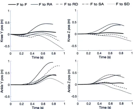
2.2 Method used to estimate foot flat by thresholding the difference between shank segment velocity and ankle angle velocity. . . . . 24 2.3 Knee and ankle anterior-posterior (Y) and longitudinal (Z) position signals
calculated using an IMU for five representative strides made by the same subject with different task transitions. All plotted strides except flat-to-flat were led by the biological leg. Signals are plotted for the window [t~i: t (i1 ] to show behavior for the entire stride. Knee Z position is displayed offset by the subject's shank length to allow easy comparison between axes. . . . . . 25 2.4 Error metrics from 20-fold cross-validation of LDA classifiers built on feature
sets S(ensed), E(xpanded), and T(ranslational) extracted from signals in the window [ti : ti) + tD] for tD = 400 ins. Error bars represent ±1 SEM. (a) Composite error of the prediction vector combined from all folds. Numbers above error bars represent the total feature count of each set. (b) Transitional error of the prediction vector combined from all folds. (c) Steady state error of the prediction vector combined from all folds. . . . . 26
2.5 Shank orientation error distribution as calculated during gait. . . . . 27 2.6 Error of vertical ankle position estimate during a circuit comprising stair
as-cent and desas-cent. .. ... ... ... . .. .. 27 2.7 Effect of signal cutoff time post foot-off on the composite error from 20-fold
cross validation attained by the S(ensed), E(xpanded), and T(ranslational) feature sets. Error bars represent ±1 SEM. . . . . 28 2.8 Effect of sequential addition of signals used to make the T(ranslational)
fea-ture set on composite error. Signals were selected based on a sequential for-ward search where performance for each signal set was measured by the com-posite error from 20-fold cross validation. The resulting selection is displayed from left to right on the graph. Y signals are anterior-posterior components and Z signals are longitudinal components. Error bars represent +1 SEM. 29 3.1 (a) The TF8 mechatronic system architecture is a reaction force series elastic
actuator with an on-board embedded control system. (b) The TF8 has 115 degree total ROM with 35 degrees of dorsiflexion. (c) The Control Unit is a derivative of the FlexSEA embedded system from Dephy, Inc. that includes a motor driver unit and mid-level controller. A state machine runs on the mid-level controller that defines a desired impedance command and runs a closed-loop torque controller to define the behavior of the physical actuator. 37 3.2 Stride time point snapshots. Stride objects include both initial and target
stance periods to allow back-estimation of stride terrain using data from the target stance period. . . . . 38 3.3 Method used to estimate ground slope, combining knowledge of shank pitch
and ankle angle to achieve the most accurate possible estimate. Estimation involved averaging the value a - 3 during a time when the foot was detected to be flat on the terrain. The method to detect a flat foot is described in
Chapter 2. ... .. 39
3.4 (a) Heuristic back-estimation of stride terrain based on horizontal and vertical ankle joint positions Ay(n) and Az(') and estimated terrain angle 6(n+1) in
[tn,
t ']. (b) A visualization of these parameters for a representativeterrain transition. . . . . 40 3.5 Estimated sagittal plane ankle translations for strides taken by all subjects,
plotted along with underlying terrain geometries. Scattered points indicate end-of-stride estimated ankle positions. . . . . 41 3.6 Measured horizontal displacement distributions for each terrain. For terrains
which horizontally constrain foot position we also include dashed black lines indicating the expected ankle displacement. In particular, we assumed that ankle displacement is horizontally constrained during stair ascent and stair descent. Stride proportions are relative to the stride population for the cor-responding terrain. . . . . 42
3.7 Measured vertical displacement distributions for each terrain. For terrains which vertically constrain foot position we also include dashed black lines indicating the expected ankle displacement. In particular, we assumed that ankle displacement is vertically constrained during stair ascent, level ground walking, and stair descent. Stride proportions are relative to the stride pop-ulation for the corresponding terrain. . . . . 43 3.8 Normalized histograms of ground slope estimates for all ramp descent, forward
level ground, and ramp ascent. Distributions for each terrain are normalized relative to the number of strides with the corresponding terrain label. . . . 44 3.9 Ankle trajectories and slope estimated from strides made while walking on
level ground at different speeds. . . . . 45 3.10 Mean fold prediction errors from performing forward feature selection using
mean 10-fold cross validation accuracy of a linear discriminant analysis clas-sifier. Each bar represents the optimal error attained when classifying on features extracted from windows beginning at a foot-off event and ending at different cutoff times post foot-off. Values at the top of the error bars indi-cate the number of features for the best model. The dashed line indiindi-cates the composite classification accuracy of our heuristic. . . . . 46 3.11 Feature selection history from using 10-fold cross validation of a linear
dis-criminant analysis classifier on features extracted between foot-off and 250ms post foot-off. This time point achieved the lowest optimal error of all tested cutoff tim es. . . . . 47 4.1 Mean power profiles for all terrains of interest over a gait cycle, compounded
from data in [5] and [58]. . . . . 58 4.2 Comparison of terrain-wise real-time prediction accuracies across all subjects
with and without adaptive control. . . . . 59 4.3 Peak foot-strike unaffected-side normal ground reaction force. Error bars
represent ±1 s.d. Significance measurements were based on performing a one-way ANOVA across control paradigms for each subject. Number of asterisks indicate p-values smaller than 0.05, 0.01, 0.001, and 0.0001 respectively. Stair data for subject 5 are missing due to a flaw in data collection. Only two groups are shown for level ground walking because, in this case, terrain adaptive control was the equivalent of level ground walking. . . . . 60 4.4 Mean peak normal ground reaction force profiles for subject 3. Bands
Chapter 1
Introduction
1.1
Overview and specific aims
Although great advances have been made in the design and control of leg prostheses, per-forming different walking tasks such as traversing ramps or stairs and transitioning between these tasks remains a major challenge for the field. As a result, people with leg amputations often exhibit gait dynamics not consistent with those of biological walking, thereby increas-ing their risk of developincreas-ing amputation-associated comorbidities and significantly limitincreas-ing their mobility. The objective of my thesis work is thus to improve metrics of gait function associated with comorbidity pathogenesis by developing a control system for a prosthesis that can automatically adapt its behavior to the user's desired walking task.
In this work, which specifically focuses on the case of below-knee amputation, I develop a control system that can accurately anticipate and respond to changes in walking tasks in a powered transtibial prosthesis. Predictions of walking tasks are made by recognition of preparatory biomechanical patterns imposed upon the user by the ground terrain and employ only the sensors onboard a powered prosthesis. In response to these predictions, the prosthetic control system promptly switches to a corresponding task specific control law which improves various biomechanical aspects of gait for that terrain, such as by lowering peak ground reaction force on the contralateral limb. Broadly, this work was enabled by the completion of three aims:
1. Completion of a comparative pattern recognition analysis evaluating the use of inertial measurement onboard a prosthetic limb to accurately predict transitions in the ground terrain. In this work, I demonstrated that using an inertial measurement unit (IMU) to estimate the translational motion of the knee and ankle joints during every stride allows higher terrain prediction accuracy than that enabled by using only raw IMU signals. Additionally, this accuracy was on par with state-of-the-art methods employing sensors external to a prosthesis.
2. Development of a method to directly measure the terrain geometry while a person is walking and accurately predict terrain using a heuristic that generalizes across multiple subjects. This method relies on accurate estimation of ankle horizontal displacement, ankle vertical displacement, and ground slope. Using this method, here I also develop
Human Step-to-Stop Tranmilon Amputee with UniMral Weak Push-Off
slower faster
COM P~h
Pendulum Step-to-Step Pendulum Transition
Greater CO PO&CO
Figure 1.1: Borrowed from [5]. Center of mass (COM) dynamics during step-to-step transi-tion for normal and amputee gait. Weak push-off (PO) from trailing prosthetic side causes excessive collision (CO) force, high dissipation of mechanical energy, and more time spent on the intact side.
the first accurate intent recognition algorithm that relies only on a heuristic set of rules rather than a machine learning classifier, providing numerous benefits including interpretability, easy troubleshooting, and tunability.
3. Development of terrain-specific controllers and validation of a terrain adaptive control system across multiple subjects. This validation was performed on the basis of real time terrain prediction accuracy and the ability of each controller to normalize gait metrics when evaluated in steady state on its corresponding terrain.
1.2
Background and motivation
1.2.1
Prevalence of leg amputation and prosthesis use
There are approximately 1 million people in the United States with lower limb amputation [1] and about 130,000 such amputations are performed each year [2]. A study in 2009 found that approximately 84% of participants with a leg amputation regularly used a prosthesis [3]. Additionally, mean daily prosthesis use tends to increase with time post amputation. A survey of patients with lower limb amputation of non-traumatic etiology showed that the mean daily time spent walking with a prosthesis was 3.4 hours and 4.3 hours respectively for patients who had been fitted 4 months and 12 months post amputation [4]. These results are evidence that walking is a common and desired activity among people with amputations.
1.2.2
Comorbidities associated with long term prosthesis use
While leg prostheses have substantially improved quality of life for people with leg am-putation, long-term prosthesis use causes various asymmetries to manifest in gait [6-8].
These chronic kinetic or kinematic asymmetries are mechanisms for a variety of amputation-associated comorbidities and adverse effects including osteoarthritis [9-11], chronic back pain
[12-14], fatigue [15, 16], and heightened fall risk [17, 18].
Contralateral knee and hip osteoarthritis
Traumatic osteoarthritis occurs due the destruction of cartilage within a movable joint, and can lead to increased joint pain and decreased range of motion and shock tolerance. Common mechanisms for osteoarthritic development include increased load demands and impacts on the joint, high external adduction moment, and generalized joint overuse [18]. In the case of unilateral lower limb amputation and long term prosthesis use, over-reliance on the intact side for dynamic support substantially contributes to each of these factors [10, 19] and significantly increases prevalence of osteoarthritis of the intact-side hip and knee joints compared to the general population [11].
Back pain and scoliosis
While back pain is common among the general population, people with lower limb ampu-tations are at an even greater risk for developing this symptom [12]. Various studies have concluded that over half of participants with amputated legs had bothersome back pain that commenced after their amputation, and a substantial fraction reported that this pain was either the worst pain problem they experienced or that it had a substantial impact on their lifestyle [12, 20].
Fatigue
Locomotion fatigue in people with leg amputations results from a metabolic cost of walk-ing higher than levels for biologically intact individuals of correspondwalk-ing size and weight [15]. Higher metabolic cost is principally caused by insufficient provision of power from the prosthetic side during the step-to-step transition [21] (see Figure 1.1), which results in heightened collision forces on the leading leg and a large dissipation of mechanical energy [22]. This idea is also supported by studies on powered ankle foot prostheses, which can normalize metabolic cost of walking by providing a biologically appropriate power profile to the trailing prosthetic leg [23].
Fall risk
Prevalence of falling is higher among leg amputees than it is among the general population [17] and can often be attributed to gait asymmetries including insufficient prosthetic foot ground clearance or excessive trailing leg push-off power during descent tasks. Additionally, one study found that fall risk was significantly higher among participants with unilateral as opposed to bilateral below-knee amputations [16], further indicating a connection between gait asymmetry and fall risk. Finally, fall risk has been found to be positively correlated with back and joint pain [17], both of which are linked to gait asymmetry.
1.2.3
Lower limb prostheses
Leg prostheses aim to replace the structure and function of absent biological limbs. Prior to the 21st century, all commercially available leg prostheses were passive devices designed to best recapitulate the form and certain mechanical properties of biological legs. Passive pros-theses are still common today, mainly due to their low weight and high reliability. However, the main limitation of these devices is that they provide the same biomechanical behavior across every lower limb activity. The second is that they are unable to perform positive work, which is a part of many lower limb tasks such as biological level ground walking and stair ascent. [5, 24]. Such devices often fail to recapitulate symmetric gait [7, 8], resulting in the aforementioned amputation-associated comorbidities.
Recently, powered prostheses with onboard computers and motorized joints have ad-dressed these limitations by introducing the ability to dynamically adapt to gait by mod-ulating joint angles and torques [25-27]. As a result, these devices have great potential in preventing or alleviating amputation-associated gait pathologies by increasing stability and energy return, making gait more symmetrical, and conferring appropriate power generation or dissipation requirements for a given task. A major challenge that comes with the develop-ment of powered prostheses lies in their control, whose aim is to measurably mimic biological gait dynamics across a large variety of conditions affecting human walking. Thus, the central focus of this work is to develop and evaluate numerous methods to mimic biological gait on different ground terrains and to transition between these ground terrains relying only on the sensors on-board a prosthesis.
1.2.4
Joint proprioception and biological limb control
Within intact and healthy human limbs, joint dynamics are controlled by a neural signal relying on the ability to sense the current relative position of one's limb. This sensation, known as proprioception, provides the fundamental feedback necessary to inform the timing and magnitude of muscular contraction necessary for reliable control of one's extremities [28]. This relationship is particularly important in the control of human legs, which frequently must provide support and power while under heavy load [29].
For a given degree of freedom in a biological joint, proprioception is enabled by the me-chanical coupling between an agonist and antagonist muscle pair through tendons interfacing with the bones comprising the joint [30]. In this relationship, contraction of the agonist mus-cle is enabled by an efferent neural signal commanding a desired activation level to the musmus-cle through motor neurons. The joint is then rotationally accelerated in response to the force applied to the muscle, simultaneously applying a tension force to the antagonist muscle. The amount of resultant stretch in the antagonist is then sensed by Golgi tendon organs and relayed to sensory neurons, which then relay this information to the central nervous system, where it is interpreted as joint position [31].
1.2.5
Main challenge of prosthetic control
Traditional amputation procedures remove not only biological limbs themselves but also the proprioceptive relationship used for their control. In particular, traditional amputations
either remove residual muscles entirely or suture them in place. While this procedure allows the immobilized muscle to contract, it removes the mechanical connection between agonist and antagonist, preventing one from mechanically affecting the other. This severing of the agonist-antagonist relationship removes proprioceptive feedback inherent to the way humans control their limbs.
The loss of proprioception inherent to the traditional amputation procedure creates a huge hurdle for the field of prosthetic control, which aims to enable the most natural control of a synthetic limb possible. In particular, the dream of prosthetic control for many decades has been to enable direct neural control, which would allow control of a synthetic limb in much the same way a biological limb is controlled. But in the absence of proprioception, direct neural control has proven to be a major challenge [32, 33]. Because high-quality limb position information is required for effective limb control, removal of this feedback signal effectively prevents a person from knowing when and by how much they should activate their residual musculature. As a result, even in the case of high-fidelity readouts from the residual musculature, direct use of these signals to control prosthesis dynamics has proven insufficient for recapitulating desired behavior in synthetic limbs [33]. Thus a workaround is necessary.
1.2.6
Intrinsic control
One quality of the lower limbs that differentiates them from the upper limbs is that most lower limb activities are repetitive and periodic. Activities such as walking on level ground, descending stairs, running, and swimming rely on a relatively consistent sequence of events, during which the person engaging in an activity reproduces the same motions in a consistent fashion and at a predictable and consistent rate. Furthermore, each control action can often be divided into a series of sequentially progressing states. The most common example of this is level ground walking, which typically involves a sequence of pushing each limb off the ground with the toe, swinging it through the air, landing on the heel, rolling over the foot, and then repeating.
For a given activity, each state can be characterized by a certain biomechanical behavior, and we can obtain a robust mathematical approximation of this behavior without relying on any neural signal. An example of this is illustrated in Figure 1.2. Borrowed from [34], this figure illustrates the relationship between ankle angle and ankle torque during a typical stride, averaged from ten people walking at a consistent speed. In this example, there are four represented states, and points 1 to 4 represent transition points between states, where the angle-torque relationship significantly changes. In this work, the authors were able to leverage the observed relationships in level ground walking to design and evaluate a prosthetic control system that enabled normal gait simply by emulating these characteristics. As a result, gait was normalized successfully enough that it resulted in a net improvement in the metabolic cost of walking over that observed using a passive prosthesis.
This study and others like it have demonstrated that, in the case of lower limbs, it is possible to use control methods that can infer the desired biomechanical behaviors of the user independently of muscle activation, provided that the mechanics of the desired activity are well understood. Such control paradigms are referred to as "intrinsic" because they rely only on sensors onboard a powered ankle foot prosthesis. In the example above, these needed
'p 4IA
-1.2
-OA-0.2
SW
0•-&-45(1) Hee-trike
(2) Foot-flat
(3) Max. Dorsifiexion
(4) Toe-off
PP
W~ 0.13J/kg
(3) (4)_CD(2)
;(3)
t kf1.(2)P
AnMe Angle (deg)(2)
(1)-(2): Controlled Plantar Flexion (CP)
(2)-(3): Controled Dorsiflexion (CD)
(3)-(4): Powered Plantar Flexion / Push-off Phan (PP) (4)-(1): Swing Phase (SW)
W = Work done at the ankle joint
Figure 1.2: Figure borrowed from [34] showing an example of using a state machine to represent the periodic relationships between ankle angle and ankle torque during level ground walking.
only be encoders and strain sensors allowing estimation of prosthetic ankle angle and torque. Such intrinsic control methodologies have been successfully applied in other areas such as stair ascent and descent [35], or incline traversal [36].
Walking task adaptation in leg prostheses
While dynamics within any given activity performed at a given rate are relatively predictable, transitions between activities are more random and difficult to predict. These might include transitions from sitting to standing or from walking on level ground to walking on an incline. When such transitions call for biomechanically different behaviors, or behaviors anticipating the transition before it occurs, it becomes necessary to promptly detect them and adapt the prosthetic control paradigm in such a way that allows a seamless, natural, and comfortable transition.
The recent advent of powered leg prostheses has introduced the ability to modulate actu-ation in response to changes in user walking task such as level ground walking, stair ascent or descent, and ramp ascent or descent. Such behavior-dependent actuation is important given the variability of leg biomechanics among these modes [37, 38]. While various advances have been made in steady-state control methodologies within certain tasks [23, 35], accurate and robust walking task prediction remains an active area of research.
Perhaps the most significant determinant of gait dynamics is the ground terrain. Numer-ous studies have shown that walking on level ground, inclines, or stairs can have significant effects on the kinetics and kinematics of lower limb joints. One example of this is demon-strated in Figure 1.3, which shows the high variability of ankle kinematics and kinetics during level ground walking, stair ascent, and stair descent. To address the issue of terrain depen-dent lower limb biomechanics, one aim of our work has been accurate, real-time prediction of terrain for the purpose of switching to a corresponding control policy. We demonstrate methods for real-time prediction of upcoming ground terrain using only the sensors available aboard a powered prosthesis.
A variety of sensing modalities have been proposed to solve the prediction problem. These have been based on using pattern recognition approaches on mechanical signals such as user kinetics and kinematics, electromyography (EMG), or optical signals obtained from the environment. Specific choices for sensing modalities have included inertial measurement [39-41], joint angle encoding [39, 42], foot-ground kinetics [43, 44], electromyography [45-47], and optical distance sensing [40, 48], with classification features being extracted from signal windows defined by gait events such as foot-strike and foot-off. Some of these approaches have employed wearable sensors, including multiple inertial measurement units (IMUs) positioned at different locations on the leg [41] and waist-mounted optical distance measurement [40, 48], but these systems required the user to don additional sensors and were not robust due to sensor donning variability, and in the case of optical distance sensing, reliance on a line of sight.
Recent studies have demonstrated that the fusion of multiple sensing modalities affords a multiple-percent increase in prediction accuracy over either sensing modality alone [40, 42, 49]. Among these are neuro-mechanical sensor fusion approaches [42, 49], which combine mechanical and surface EMG signals. While they yield the most accurate mode prediction results of any approach in a laboratory setting, these methods have limited robustness due
A 46 -30 0.5 2.6 0 -6
Lae-grun -aird Asent Stair DeMb cn - Ale-bofed - Inlcurnmbaa.8 •••• m
4ao
160-0 20 40 60 0 0 20 40 60 60 0 20 40 60 60 100
% Gal cycl % Galt cyde % Get cyde
Figure 1.3: Figure borrowed from [5] showing the response of ankle kinetics and kinematics to level ground walking, stair ascent, and stair descent.
to their reliance on a surface EMG signal, whose quality and composition can vary with residual limb constitution and state as well as sensor placement. Due to the inconsistent quality of EMG, the performance of an EMG-based walking task prediction system would be significantly affected by variation in the location and quality of sensor donning, perspiration level [50], skin temperature [51], subcutaneous fat [52] and obstructions such as androgenic hair or epidermal scarring. Additionally, the daily application of EMG sensors securely and in the correct location is cumbersome and inconvenient for the user.
In addition to terrain prediction, a parallel challenge is biomimetic terrain adaptation, whose dynamics can also vary significantly based on both the particular user and the user's walking state. To address these challenges, we investigate methods to develop adaptive con-trol algorithms within specific terrains. To this end, we determine whether tuning prosthesis control parameters to attain local joint dynamics matching those of intact limbs can lead to overall increased biomimicry of gait in people with amputations.
Finally, we combine real-time terrain prediction and terrain adaptation into a terrain-adaptive control system for a below-knee prosthesis. We show that the system is able to accurately predict the ground terrain of every stride and adapt to the terrain biomimetically, conferring important biomechanical advantages to its users, including appropriate ground clearance during ascent tasks, power dissipation during descent tasks, and mitigation of gait asymmetry. Functionally, these advantages serve to decrease fall risk, reduce fatigue, and diminish the risk of osteoarthritis, scoliosis, and other comorbidities associated with lower limb pathology or amputation.
0 5
5
lb 5 0 A 5 Am VFW-5 .5Chapter 2
Offline terrain classification analysis
using only intrinsic sensors
The work in this chapter has been published in [53].
2.1
Abstract
Objective: Walking task prediction in powered leg prostheses is an important problem in the
development of biomimetic prosthesis controllers. This article proposes a novel method to predict upcoming walking tasks by estimating the translational motion of leg joints using an integrated inertial measurement unit. Methods: We asked six subjects with unilateral transtibial amputations to traverse flat ground, ramps, and stairs using a powered prosthesis while inertial signals were collected. We then performed an offline analysis in which we simulated a real-time motion tracking algorithm on the inertial signals to estimate knee and ankle joint translations, and then used pattern recognition separately on the inertial and translational signal sets to predict the target walking tasks of individual strides. Results:
Our analysis showed that using inertial signals to derive translational signals enabled a prediction error reduction of 6.8% compared to that attained using the original inertial signals. This result was similar to that seen by addition of surface electromyography sensors to integrated sensors in previous work, but was effected without adding any extra sensors. Finally, we reduced the size of the translational set to that of the inertial set and showed that the former still enabled a composite error reduction of 5.8%. Conclusion and Significance: These results indicate that translational motion tracking can be used to substantially enhance walking task prediction in leg prostheses without adding external sensing modalities. Our proposed algorithm can thus be used as part of a task-adaptive and fully integrated prosthesis controller.
2.2
Motivation
The recent advent of powered leg prostheses has allowed modulation of control strategies depending on user actions. Such task-dependent actuation is important given the large vari-ability in leg biomechanics between tasks such as level ground walking and ramp and stair
traversal [5, 37, 38, 54-59]. While various advances have been made in prosthesis control methodologies within each of these tasks [23, 35, 36, 60], a continuing area of research is to accurately and promptly predict transitions between tasks, and doing so without encumber-ing the user with devices external to their prosthesis.
The most effective walking task prediction methods to date have incorporated pattern recognition on signals obtained from a combination of integrated prosthesis sensors and ex-ternal sensors such as wearable inertial measurement units (IMUs) [41, 61], optical distance sensors [40, 48], and surface electromyography (sEMG) electrodes [42, 49, 62-64]. While these attempts often resulted in accurate and prompt prediction of walking task across users, approaches based on external sensors encumber the user with additional sensor don-ning requirements and introduce performance dependency on dondon-ning technique and quality. Specifically for sEMG based approaches [42, 45-47, 49, 62], performance in a non-laboratory setting is uncertain because sEMG signals vary significantly with physiological factors in-cluding perspiration level [50], skin temperature [51], and subcutaneous fat thickness [52].
More integrated approaches have included combinations of inertial, mechanical, and ki-netic sensors contained within the prosthetic assembly [44, 65-67], but these methods
recog-nized rather than predicted tasks, making most task determinations during or after ground
contact. In a real-time controller, such delays would preclude anticipatory control deci-sions necessary to mimic biological gait such as plantarflexion for stair descent [5, 55] or dorsiflexion for ground clearance in ascent tasks [55, 57].
Given the need for anticipating tasks and the disadvantages of relying on external sensors, an important goal is to predict tasks robustly using only integrated sensing modalities. In this work, we address this need by developing a novel and improved method for using an integrated IMU for walking task prediction. Previous work has shown that incorporating physiological sensors [42, 49, 62, 63] or physiologically relevant signals [61, 64, 66] can enhance task prediction accuracy. In the same spirit, we aim to produce physiologically relevant signals, but relying instead on a non-physiological and mechanically integrated sensor. In our offline analysis, we employ signals from an IMU to generate physiologically meaningful estimates of leg joint translational motion and perform pattern recognition on the resulting signals to determine the target task of every stride. Our results demonstrate that this novel treatment of inertial signals enables substantial performance improvement in walking task prediction, on par with that seen by the addition of external (sEMG) sensors to mechanical sensors in previous work [42, 49, 63], but effected without the addition of external sensors. The implication of our work is a method that can be combined with other integrated sensing modalities as part of a real-time task-adaptive leg prosthesis controller that is robust across users and physiological conditions.
2.3
Methods
2.3.1
Data collection
Overview
Six subjects with unilateral transtibial amputations (detailed subject attributes in Table 4.3) and ability level K4 completed walking circuits along two terrain setups including a
S-offse
accels
Rigid body SaA, aA,K AK A,KSF Projection + t
A equation
te a
gyros
+-SR
Gravity
Zero Projection festimate
offset &
Figure 2.1: Motion integration algorithm estimating knee and ankle translational motion AK AK and 'A,K and rotation matrix R using an IMU composed of accelerometers and gyroscopes. Zero offsets collected at the beginning of each trial are first subtracted from the gyroscope outputs producing s0, which is then projected onto global axes and integrated to calculate sensor-to-global frame rotation matrix R. w0 and Sa are used as input into the rigid body equation, which estimates sensor-frame accelerations at knee and ankle points
dA,K. These are then projected onto global axes using R, adjusted by subtracting the gravity estimate to obtain aA,K, and integrated to obtain XA,K and PA,K.
four-step staircase (0.17m rise, 0.25m run) and ramp (12-degree inclination, 2.Om long) while wearing a powered ankle-foot prosthesis. Prosthesis sensor data and leg kinematics measured with motion capture were logged for offline processing. This study was approved by the Massachusetts Institute of Technology Institutional Review Board.
Equipment
Subjects completed all walking trials using the BiOM ankle-foot prosthesis (BionX Medical Technologies, Bedford, MA) coupled to a carbon composite foot of the subject's normally used size and stiffness. The assembly was attached to each subject's own custom fitted socket through a pylon of appropriate length. In each trial, sensor-frame acceleration sa and rotational velocity sw sampled from an integrated six-axis IMU (i6g three-axis accelerom-eter, MMA7361LC; yaw rate gyroscope, ADXRS620; integrated dual-axis rate gyroscope, IDG500), estimated ankle torque r, and estimated ankle angle 0 were remotely logged. All signals were sampled at 167 Hz.
A 12-camera Vicon 8i motion capture system with Vicon Nexus 1.8.5 was used to track subject kinematics relative to the terrains. This system was employed solely to facilitate automatic labeling of walking tasks for each trial.
Subject preparation
Prior to completion of walking trials, the BiOM prosthesis assembly was aligned to each subject's custom fitted socket, and a foot cover and shoe were donned over the prosthetic foot. Prosthesis controller parameters were then tuned to the subject's particular gait biome-chanics using a manufacturer provided wireless interface and tuning protocol. Subjects then practiced walking with the prosthesis for ten minutes.
Motion capture markers were applied to each subject's lower body segments and to all terrain setups sufficiently to enable automatic stride-by-stride labeling of walking task post
Table 2.1: Subject Attributes
ID Sex Age Ht(m) Wt(kg) Affected side
1 M 66 1.83 97 R 2 M 59 1.90 100 L 3 M 35 1.78 86 R 4 M 44 1.90 91 R 5 F 28 1.68 59 L 6 M 31 1.75 73 L data collection. Walking trials
Each subject completed multiple circuits at self-selected pace separately on a staircase setup and ramp setup. For both setups, each circuit comprised a flat ground traversal, terrain ascent, subsequent flat ground traversal on a level platform, and terrain descent. Stair traversal was performed in a step-over-step fashion. Prosthesis sensor signals were logged to a computer through a wireless transmitter and motion capture data was logged using the Vicon system. All trials were initiated with a three-second static standing period to allow calculation of a zero offset for gyroscope measurements and a gravity estimate from the accelerometers.
2.3.2
Offline Classification Analysis
Overview
We compared the task prediction performance of sensed signals sd and sw to that of derived knee and ankle translational motion signals for a collection of strides extracted from the walking trials. Target walking tasks included flat ground walking (F), ramp ascent (RA), ramp descent (RD), stair ascent (SA), and stair descent (SD).
Trial preprocessing
Marker trajectories were reconstructed from camera data using Vicon Nexus 1.8.5. Prosthesis accelerometer signals were low-pass filtered using a first order Butterworth filter with a 20 Hz cutoff. Marker trajectories were then manually synchronized to prosthesis sensor data by resampling the trajectories and manually aligning periods of elevated r with periods of low horizontal velocity in prosthetic ankle markers.
Extraction of individual strides
Prosthesis and motion capture data from each trial was divided into individual strides i defined by an initial ground contact time ti, foot-off time t i, and subsequent ground
contact time to . to
,
tof, and t + were detected using a threshold on r and each stride's target walking task was identified using motion capture data. Finally, strides from all trials were combined into one list, and those with short swing durations (t i - t< 400 ms) were removed to filter small strides such as side-to-side shuffles or others that were not made in a predominantly forward direction. We selected a 400 ms cutoff to allow for retention of > 99% of strides in the list while maximizing the size of the time window available for feature extraction.
Simulation of motion tracking algorithm
We used a motion integration algorithm on a and SO to estimate global-frame translational motion including ankle joint acceleration dA, knee joint acceleration d1
K (combined here as
aA,K), ankle and knee joint velocities VA,K, ankle and knee joint positions IA,K, and sensor-to-global frame rotation matrix R (Fig. 2.1). First, we calculated sensor-frame accelerations at the knee and ankle joints sdA,K from Sd and SW using an equation for determining a point acceleration in a rigid body:
-.* S-4 5-. 5-. 5- S-4 5-.
SA,K= d+ WX WX rA,K- W) X rA,K (2.1)
where srA,K are the position vectors of the knee and ankle from the IMU in sensor frame and s was low-pass filtered at 30 Hz. srA was manufacturer provided, and SrK was calculated as:
SrK = AT [0;0;L] + s-A (2.2)
where A was a manufacturer provided sensor-to-prosthesis rotation matrix and L was shank length measured using motion capture. This calculation assumed that the prosthesis and residual shank frames were equivalent and that the knee joint was directly above the ankle joint in these frames. Next, we projected saA,K onto global axes using R and subtracted the gravity estimate to attain global-frame joint accelerations dA,K. R was calculated by
integrating W, the global axis projection of Sw'. Finally, dA,K was integrated twice to attain VA,K and PA,K.
Due to bias in sa and SO, integrated signals VA,K, PA,K, and R were subject to accumu-lating error. To bound this error, we reset these signals at least once during every stance period, and employed slightly different policies for resetting orientation and velocity/posi-tion. In order to detect the appropriate conditions for performing these resets, we made use of two additional underlying signals. For orientation resets we employed a threshold on the acceleration norm |Sd,, expressed as:
| Sga - gA each (2.3)
shank rotation angle R was adjusted by a manually tuned weighting factor c as: R2,1 := sin(a) = c(Say/g)
+
(1 - c) * R2,1 (2.4) R1,1 := cos(a) = 1 - R2,1 (2.5) R2,2 := sin(a) = R2,1 (2.6) R1,2 -cos(a) = -R 1,1 (2.7) (2.8) where a is the shank pitch angle and c 0.02. This value was tuned to minimize the mean absolute orientation error over the course of one trial as compared to data extracted from motion capture.For position resets we employed a threshold on the norm difference between sagittal shank rotational velocity sx and ankle rotational velocity 6. As illustrated in 2.2, the assumption underlying this calculation was that these values would be closest when the foot is flat on the ground. The calculation and threshold we employed can be expressed as:
6 ISW - 1 C (2.9)
where 6 was filtered using a 50Hz, 2nd order low pass Butterworth filter and C = 1.2rad/s. This threshold was chosen empirically to allow for at least one velocity/position reset per stance period, and was likely high due to deflection of the prosthetic foot during roll-over. At the velocity reset time tR integrated signals were reset by modeling the shank as a vertical lever rotating in the sagittal plane about a fixed hinge at the ankle joint:
#A (R) :=[0; 0; 0] (2.10)
VA (tR) : [0; 0;0] (2.11)
PK(ti): L[0; R2,1 (tR (); R1, 1(ti) (2.12) UK (tR) := X L [0; R1, 1(tR) -R2,1 (tR) (2.13)
(2.14) where the components represent, in order, the frontal, anterior-posterior, and longitudinal axes.
Extraction of feature sets
For all strides, we created three separate feature sets including S(ensed), T(ranslational), and E(xpanded). All feature sets were comprised of the maxima, minima, means, and standard deviations extracted from associated signals in the window [tli : t2i + tD] where tD = 400 ms. S was extracted from sw and Sa (6 signals total). T was extracted from sagittal plane translation signals including anterior-posterior and longitudinal components of dA,K, VA,K, and PA,K, as well as shank pitch angle and velocity, computed using Euler angle conversion on the prosthesis-to-global rotation matrix P RA T (14 signals total). Non-sagittal translation signals were excluded from T to reduce feature set size and were based on the assumption
G
96WX
0
~
WX
6WX
WX
Figure 2.2: Method used to estimate foot flat by thresholding the difference between shank segment velocity and ankle angle velocity.
that walking mechanics occur predominantly in the sagittal plane. Finally, E contained both features of S and features extracted from integrated and differentiated SW' and Sa (18 signals total, differentiated signals were low-pass filtered at 30 Hz). E was included as a control because we expected that naively increasing the number of generated signals would improve pattern recognition accuracy, yet we were specifically interested in determining the utility of translations. All feature sets were normalized to zero mean and unit variance across all strides.
Task prediction analysis with fixed cutoff
For S, E, and T, we performed cross validation using linear discriminant analysis (LDA) on 20 randomly generated, approximately equally sized folds (19 folds in the training set, 1 fold in the test set, repeated such that each fold was the test set once). All LDA training was performed using uniform priors and cost matrix.
Error metrics were calculated based on the combined prediction vector from all 20 folds given knowledge of the actual target tasks of each stride. In particular, we report three error metrics: "composite" (calculated on all strides), "transitional" (calculated on strides with different initial and final tasks), and "steady state" (calculated on strides with the same initial and final tasks). We performed one-way ANOVAs for all error metrics, followed by a post-hoc Tukey test to verify performance differences between feature sets. We also report numerical confusion matrices for each feature set.
Task prediction analysis with variable cutoff
Next, we repeated the cross validation analysis for S, E, and T generated with different cutoff times tD to determine the consistency of the observed performance differences between feature sets. We report composite errors attained by S, E, and T extracted from signals in the window [ti): ti
+f
tDI for values Of tD from 0 ms to 400 ms in increments of 50 ms.-F to F -F to RA - - F to RD ---- F to SA ....- F to SD 1 , 0.5 0 ...- 0.5-0 0.2 0.4 0.6 0.8 Time (s) . ... 1 0 0.2 0.4 0.6 0.8 Time (s) E, 0 0. N 4) 1 0.5 0 -0.5 0 0.2 0.4 0.6 0.8 Time (s) 1 0 0.2 0.4 0.6 0.8 Time (s)
Figure 2.3: Knee and ankle anterior-posterior (Y) and longitudinal (Z) position signals cal-culated using an IMU for five representative strides made by the same subject with different task transitions. All plotted strides except flat-to-flat were led by the biological leg. Signals are plotted for the window [tR : to ] to show behavior for the entire stride. Knee Z posi-tion is displayed offset by the subject's shank length to allow easy comparison between axes.
Feature reduction
We were interested in ranking the predictive power of signals of T in order of marginal composite error reduction and determining whether we could reduce the size of T to that of S and still observe a significant improvement in prediction accuracy. Thus, we performed forward selection of signals in T by minimizing composite error from 20-fold cross validation for tD = 400 ms.
2.4
Results
2.4.1
Generated stride list
The generated stride list included a total of 1541 strides, with 66% of strides ending in level-ground walking, 7% in ramp ascent, 7% in ramp descent, 10% in stair ascent, and 10% in stair descent. 1 0.5 0 -0.5 1 0.5 0 0 -0.5 1 1
20 20 20
E15 915 15
516
(a) 0 T
(b)
• T (c)EFigure 2.4: Error metrics from 20-fold cross-validation of LDA classifiers built on feature sets S(ensed), E(xpanded), and T(ranslational) extracted from signals in the window [tR :
off + tD] for tD = 400 ms. Error bars represent +1 SEM. (a) Composite error of the prediction vector combined from all folds. Numbers above error bars represent the total feature count of each set. (b) Transitional error of the prediction vector combined from all folds. (c) Steady state error of the prediction vector combined from all folds.
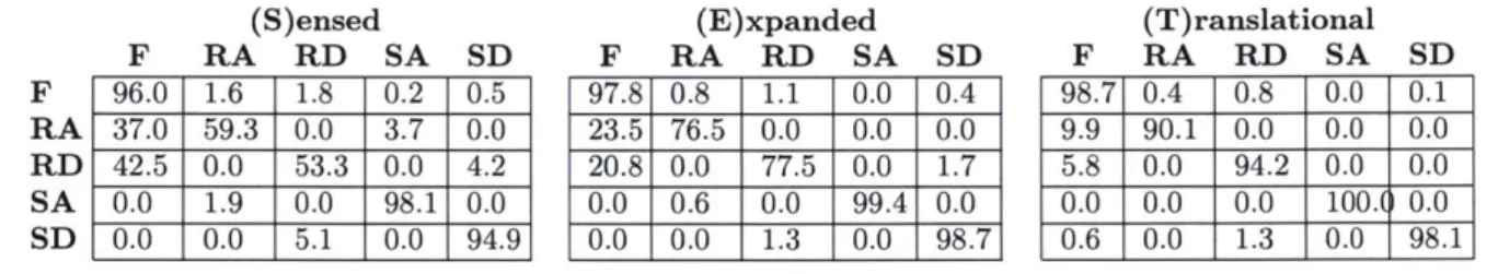
Table 2.2: Confusion matrices of 20-fold LDA cross validation (S)ensed F RA RD SA SD 96.0 1.6 1.8 0.2 0.5 37.0 59.3 0.0 3.7 0.0 42.5 0.0 53.3 0.0 4.2 0.0 1.9 0.0 98.1 0.0 0.0 0.0 5.1 0.0 94.9 (E)xpanded F RA RD SA SD 97.8 0.8 1.1 0.0 0.4 23.5 76.5 0.0 0.0 0.0 20.8 0.0 77.5 0.0 1.7 0.0 0.6 0.0 99.4 0.0 0.0 0.0 1.3 0.0 98.7 (T)ranslational F RA RD SA SD 98.7 0.4 0.8 0.0 0.1 9.9 90.1 0.0 0.0 0.0 5.8 0.0 94.2 0.0 0.0 0.0 0.0 0.0 100.( 0.0 0.6 0.0 1.3 0.0 98.1
2.4.2
Translational signals
Representative examples of calculated knee and ankle sagittal translations from strides in-cluded in the analysis are shown in Fig. 2.3. Deviations from expected anterior-posterior trajectories for the represented terrains are caused by integration error in orientation estima-tion, which can cause horizontal acceleration artifact due to gravity. Additionally, net loss in horizontal knee position during certain tasks can be explained by the tendency of some subjects to descend stairs sideways, likely to face the railing.
The performance of the motion tracking algorithm is further described in Figures 2.5 and 2.6. The former compares sagittal orientation and position estimates of the algorithm as compared to Vicon reference data from a representative trial. The latter figure shows histograms of orientation error and end-of-stride sagittal position errors. The standard deviation of a normal curve fit to the orientation error histogram is approximately 0.03 rads. The mean vertical ankle position estimation error was 6mm.
2.4.3
Task prediction analysis with fixed cutoff
Prediction error metrics for S, E, and T are displayed in Fig. 2.4. All error metrics were significantly lower for E compared to S, and for T compared to S or E (p < 0.05). In particular, training with T instead of S enabled composite, transitional, and steady state error reductions of 6.8%, 12.4%, and 4.9%, respectively, while training with E instead of S enabled corresponding reductions of 4.3%, 6.7%, and 3.5%. As a metric of performance consistency across subjects, we determined the maximum composite error for an individual
F
RA
RD
SA
2500 r 20001500 - 91000-z 500-01I -0.1 -0.05 0 0.05 0.1 0.15
Orentation eror (reds)
Figure 2.5: Shank orientation error distribution as calculated during gait.
0.8-E 0.6 - 0.4 - Motion capture Inertial measurement C 0.2 0 -0 2 4 6 8 10 12 14 16 Time (s)
Figure 2.6: Error of vertical ankle position estimate during a circuit comprising stair ascent and descent.
![Figure 1.1: Borrowed from [5]. Center of mass (COM) dynamics during step-to-step transi- transi-tion for normal and amputee gait](https://thumb-eu.123doks.com/thumbv2/123doknet/14732143.573219/11.917.136.750.135.389/figure-borrowed-center-dynamics-transi-transi-normal-amputee.webp)
![Figure 1.2: Figure borrowed from [34] showing an example of using a state machine to represent the periodic relationships between ankle angle and ankle torque during level ground walking.](https://thumb-eu.123doks.com/thumbv2/123doknet/14732143.573219/15.917.137.749.295.781/figure-figure-borrowed-showing-example-represent-periodic-relationships.webp)
![Figure 1.3: Figure borrowed from [5] showing the response of ankle kinetics and kinematics to level ground walking, stair ascent, and stair descent.](https://thumb-eu.123doks.com/thumbv2/123doknet/14732143.573219/17.917.136.739.132.415/figure-figure-borrowed-showing-response-kinetics-kinematics-walking.webp)