SPATIALLY INTEGRATED
ERBIUM-DOPED FIBER AMPLIFIERS
ENABLING SPACE-DIVISION MULTIPLEXING
Thèse
Cang Jin
Doctorat en génie électrique
Philosophiæ doctor (Ph.D.)
Québec, Canada
SPATIALLY INTEGRATED
ERBIUM-DOPED FIBER AMPLIFIERS
ENABLING SPACE-DIVISION MULTIPLEXING
Thèse
Cang Jin
Sous la direction de :
iii
Résumé
L'augmentation exponentielle de la demande de bande passante pour les communications laisse présager une saturation prochaine de la capacité des réseaux de télécommunications qui devrait se matérialiser au cours de la prochaine décennie. En effet, la théorie de l’infor-mation prédit que les effets non linéaires dans les fibres monomodes limite la capacité de transmission de celles-ci et peu de gain à ce niveau peut être espéré des techniques tradition-nelles de multiplexage développées et utilisées jusqu’à présent dans les systèmes à haut débit. La dimension spatiale du canal optique est proposée comme un nouveau degré de liberté qui peut être utilisé pour augmenter le nombre de canaux de transmission et, par conséquent, résoudre cette menace de «crise de capacité». Ainsi, inspirée par les techniques micro-ondes, la technique émergente appelée multiplexage spatial (SDM) est une technologie prometteuse pour la création de réseaux optiques de prochaine génération.
Pour réaliser le SDM dans les liens de fibres optiques, il faut réexaminer tous les dispositifs intégrés, les équipements et les sous-systèmes. Parmi ces éléments, l'amplificateur optique SDM est critique, en particulier pour les systèmes de transmission pour les longues distances. En raison des excellentes caractéristiques de l'amplificateur à fibre dopée à l'erbium (EDFA) utilisé dans les systèmes actuels de pointe, l'EDFA est à nouveau un candidat de choix pour la mise en œuvre des amplificateurs SDM pratiques. Toutefois, étant donné que le SDM in-troduit une variation spatiale du champ dans le plan transversal de la fibre, les amplificateurs à fibre dopée à l'erbium spatialement intégrés (SIEDFA) nécessitent une conception soignée. Dans cette thèse, nous examinons tout d'abord les progrès récents du SDM, en particulier les amplificateurs optiques SDM. Ensuite, nous identifions et discutons les principaux enjeux des SIEDFA qui exigent un examen scientifique. Suite à cela, la théorie des EDFA est briè-vement présentée et une modélisation numérique pouvant être utilisée pour simuler les SIEDFA est proposée. Sur la base d'un outil de simulation fait maison, nous proposons une nouvelle conception des profils de dopage annulaire des fibres à quelques-modes dopées à l'erbium (ED-FMF) et nous évaluons numériquement la performance d’un amplificateur à un
iv
étage, avec fibre à dopage annulaire, à ainsi qu’un amplificateur à double étage pour les communications sur des fibres ne comportant que quelques modes. Par la suite, nous conce-vons des fibres dopées à l'erbium avec une gaine annulaire et multi-cœurs (ED-MCF). Nous avons évalué numériquement le recouvrement de la pompe avec les multiples cœurs de ces amplificateurs. En plus de la conception, nous fabriquons et caractérisons une fibre multi-cœurs à quelques modes dopées à l'erbium. Nous réalisons la première démonstration des amplificateurs à fibre optique spatialement intégrés incorporant de telles fibres dopées. Enfin, nous présentons les conclusions ainsi que les perspectives de cette recherche.
La recherche et le développement des SIEDFA offriront d'énormes avantages non seulement pour les systèmes de transmission future SDM, mais aussi pour les systèmes de transmission monomode sur des fibres standards à un cœur car ils permettent de remplacer plusieurs am-plificateurs par un amplificateur intégré.
v
Abstract
The exponential increase of communication bandwidth demand is giving rise to the so-called ‘capacity crunch’ expected to materialize within the next decade. Due to the nonlinear limit of the single mode fiber predicted by the information theory, all the state-of-the-art tech-niques which have so far been developed and utilized in order to extend the optical fiber communication capacity are exhausted. The spatial domain of the lightwave links is proposed as a new degree of freedom that can be employed to increase the number of transmission paths and, subsequently, overcome the looming ‘capacity crunch’. Therefore, the emerging technique named space-division multiplexing (SDM) is a promising candidate for creating next-generation optical networks.
To realize SDM in optical fiber links, one needs to investigate novel spatially integrated de-vices, equipment, and subsystems. Among these elements, the SDM amplifier is a critical subsystem, in particular for the long-haul transmission system. Due to the excellent features of the erbium-doped fiber amplifier (EDFA) used in current state-of-the-art systems, the EDFA is again a prime candidate for implementing practical SDM amplifiers. However, since the SDM introduces a spatial variation of the field in the transverse plane of the optical fibers, spatially integrated erbium-doped fiber amplifiers (SIEDFA) require a careful design. In this thesis, we firstly review the recent progress in SDM, in particular, the SDM optical amplifiers. Next, we identify and discuss the key issues of SIEDFA that require scientific investigation. After that, the EDFA theory is briefly introduced and a corresponding numer-ical modeling that can be used for simulating the SIEDFA is proposed. Based on a home-made simulation tool, we propose a novel design of an annular based doping profile of few-mode erbium-doped fibers (FM-EDF) and numerically evaluate the performance of single stage as well as double-stage few-mode erbium-doped fiber amplifiers (FM-EDFA) based on such fibers. Afterward, we design annular-cladding erbium-doped multicore fibers (MC-EDF) and numerically evaluate the cladding pumped multicore erbium-doped fiber amplifier (MC-EDFA) based on these fibers as well. In addition to fiber design, we fabricate and characterize
vi
a multicore few-mode erbium-doped fiber (MC-FM-EDF), and perform the first demonstra-tion of the spatially integrated optical fiber amplifiers incorporating such specialty doped fibers. Finally, we present the conclusions as well as the perspectives of this research. In general, the investigation and development of the SIEDFA will bring tremendous benefits not only for future SDM transmission systems but also for current state-of-the-art single-mode single-core transmission systems by replacing plural amplifiers by one integrated am-plifier.
vii
Contents
Résumé ... iii Abstract ... v Contents ... vii List of Tables ... xiList of Figures ... xii
List of Abbreviations ... xviii
List of Symbols ... xxii
Acknowledgement ... xxix
Foreword ... xxxi
Chapter 1 Introduction ... 1
1.1 Capacity limit of single mode fiber links ... 2
1.2 Capacity increase brought about by new dimensions of light ... 3
1.2.1 Space-division multiplexing with multicore fibers ... 4
1.2.2 Space-division multiplexing with multimode fibers ... 5
1.2.3 Recent progress in space-division multiplexing transmissions ... 6
1.3 Critical components in space-division multiplexing ... 10
1.3.1 Novel transmission fibers ... 10
1.3.2 New devices and subsystems ... 15
1.4 Recent progress in space-division multiplexing amplifier ... 20
1.4.1 Few-mode fiber amplifier ... 24
1.4.2 Multicore fiber amplifier ... 26
1.5 Objectives and methodology ... 27
1.6 Thesis organization ... 28
Chapter 2 Erbium-doped Fiber Amplifier Theory and Modeling ... 32
Abstract ... 33
2.1 Fundamentals of erbium-doped fiber amplifiers ... 34
2.1.1 Energy levels ... 34
viii
2.2 Numerical modeling of the amplifier ... 39
2.2.1 Power propagation evolution and atomic rate equations ... 40
2.2.2 Overlap factor discretization ... 43
2.2.3 Modeling of few-mode fiber amplifiers ... 44
2.2.4 Simulation procedure ... 45
2.3 Summary ... 45
Chapter 3 Tailored Modal Gain in a Multimode Erbium-doped Fiber Amplifier Based on Engineered Ring Doping Profiles ... 48
Abstract ... 49
Résumé ... 50
3.1 Introduction ... 51
3.2 Theory and multi-ring doping profiles ... 52
3.3 Single stage simulation results ... 55
3.3.1 Single outer ring doping: fiber parameters and analysis ... 55
3.3.2 Outer ring with a central rod doping profile ... 57
3.3.3 Outer ring with inner ring doping profile ... 59
3.3.4 Differential modal gain flatness study ... 61
3.4 Application in two-stage amplifiers ... 63
3.5 Conclusions ... 66
3.6 Supplementary information ... 67
3.6.1 Overlap factor calculation ... 67
3.6.2 Fiber parameters ... 69
3.6.3 Chemical analysis results ... 70
3.6.4 Absorption spectrum analysis ... 73
3.6.5 Simulation with measured profiles ... 73
3.6.6 Swept wavelength interferometer characterization ... 78
3.7 Summary ... 79
Chapter 4 Annular-cladding Multicore Erbium-doped Fiber for SDM Amplification ... 80
Abstract ... 81
Résumé ... 82
ix
4.2 Fiber structure and design... 85
4.2.1 Fiber structure description ... 85
4.2.2 Amplifier modeling ... 88
4.2.3 Signal core design ... 89
4.2.4 Pump ring design ... 91
4.3 Amplification performance simulation ... 95
4.4 Pump injection scheme ... 98
4.5 Conclusion ... 102
4.6 Acknowledgement ... 102
4.7 Supplementary information ... 103
4.7.1 Fiber parameters ... 103
4.7.2 Cladding pumping scheme ray-tracing simulations ... 103
4.7.3 Characterization of the depressed solid-glass cladding and air-cladding AC-MC-EDFs ... 105
4.8 Summary ... 106
Chapter 5 Spatially Integrated Optical Fiber Amplifier ... 107
Abstract ... 108
Résumé ... 109
5.1 Introduction ... 110
5.2 The annular-cladding six-core erbium-doped fiber ... 112
5.3 Annular-cladding six-core erbium-doped fiber characterization ... 112
5.4 Supplementary Information ... 116
5.4.1 Pump power for strong population inversion ... 116
5.4.2 Side-pumping ... 117
5.4.3 Fiber preparation and fabrication ... 118
5.4.4 Fiber parameters ... 121
5.4.5 Ray-tracing simulation ... 122
5.4.6 Gain and noise figure measurements ... 123
5.4.7 Crosstalk ... 123
5.4.8 Data processing ... 124
5.4.9 Equivalent noise figure ... 124
x
Chapter 6 Conclusions and Perspective ... 127
6.1 Conclusions ... 128
6.2 Perspectives ... 131
xi
List of Tables
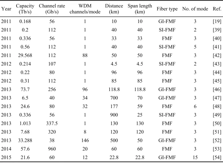
Table 1.1. Recent progress in multicore transmission ... 7
Table 1.2. Recent progress in few-mode transmission ... 8
Table 1.3. Recent progress in multicore few-mode transmission ... 9
Table 1.4. Comparison of various mode conversion and multiplexing technologies ... 17
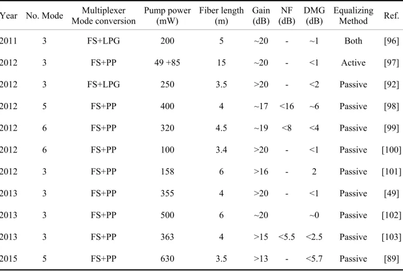
Table 1.5. Recent progress in few-mode erbium-doped fiber amplifier ... 22
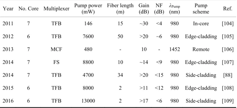
Table 1.6. Recent progress in erbium-doped multicore fiber amplifier ... 23
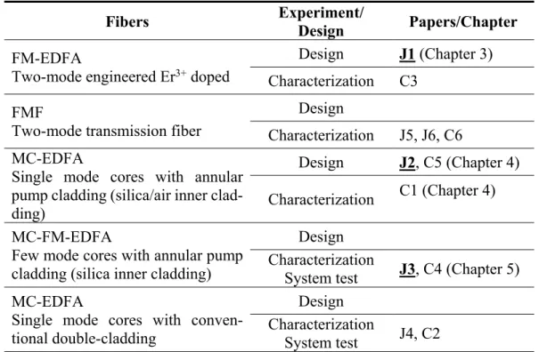
Table 1.7. List of fibers designed and characterized for space-division multiplexing transmissions and related publications. ... 30
Table 3.1. Designed fiber parameters of 2012G3 ... 69
Table 4.1. Fiber parameters ... 87
Table 4.2. Simulation parameters ... 90
Table 4.3. AC-MC-EDF parameters ... 95
xii
List of Figures
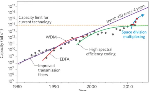
Figure 1.1. The evolution of the transmission capacity in optical fibers as evidenced
by state-of-the-art laboratory transmission demonstrations. [4] ... 2
Figure 1.2. System scheme of typical multicore fiber based space-division multiplexing ... 5
Figure 1.3. System scheme of typical multimode/few-mode fiber based mode division multiplexing ... 6
Figure 1.4. Structures for different types of optical fibers: (a) single-mode fiber; (b) few-mode fiber; (c) multimode fiber; (d) multicore fiber and (e) multicore few-mode fiber. ... 11
Figure 1.5. Pump signal combiner for multicore fibers [89] ... 18
Figure 1.6. Pump signal combiner for multimode fibers [89] ... 18
Figure 1.7. Multi-element amplifier (Left), bundled amplifier (Right) ... 26
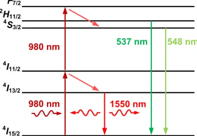
Figure 2.1. Part of Er3+ energy level, from 4I15/2 to 4F7/2 ... 34
Figure 2.2. Typical erbium absorption spectrum of Al-Ge-P co-doped silica glass ... 35
Figure 2.3. Three-level energy diagram for Er3+ in silica host glass showing pump bands at 1480 nm and 980 nm and emission from metastable level 2 to ground state level 1. ... 36
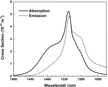
Figure 2.4. Absorption and emission cross-sections of erbium ion around 1550-nm window ... 39
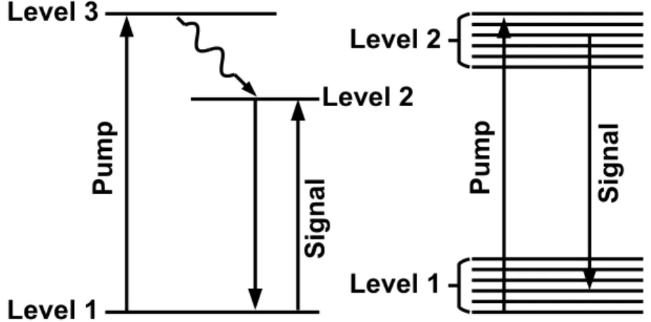
Figure 2.5. Schematic representation of three- and two-level systems ... 40
Figure 2.6. Flow chart of algorithm for amplifier simulation in Matlab® ... 46
Figure 3.1. Erbium doping profiles: (a) outer ring, (b) outer ring + center rod, and (c) outer ring + inner ring. ... 55
Figure 3.2. Differential modal gain (ΔG11-01) as a function of Roi and Roe in a 10-m long MM-EDFA with 200-mW of 980-nm pump. The dashed line represents the contour line of 20-dB gain for LP11, while more than 20-dB gain is obtained inside the shaded area. The black dot indicates the parameters of interest for the outer ring design. ... 56
xiii
Figure 3.3. Differential modal gain (ΔG11-01) in a MM-EDFA with a fixed outer ring
profile (Rob = 5.5 μm and Roe = 7.5 μm) and for varying center rod doping
profiles. Pump power is Pp = 200 mW and doped fiber length is 7 m. The
solid line indicates the contour line of ZDMG (ΔG = 0 dB). The marker identified with a star corresponds to ΔG = +2.6 dB while the square marker indicates ΔG = −1.8 dB. The shaded area surrounding the ZDMG line depicts the region where |∆G| <1 dB. ... 57 Figure 3.4. Differential modal gain as a function of pump power in a 7-m long
MM-EDFA with an outer ring + center rod doping profile. The three solid markers correspond to doping profiles identified in Figure 3.3. ... 58 Figure 3.5. Input and output signal power spectra of both modes for the outer ring +
center rod (Rce = 2.0 μm, ρc = 0.3) doping configuration in a 7-m long
MM-EDFA pumped with Pp = 160 mW power. Insets show enlarged
views of the input and output power spectra. ... 59 Figure 3.6. Differential modal gain (ΔG11-01) in a 7-m long MM-EDFA with a fixed
outer ring profile (Roi = 5.5 μm and Roe = 7.5 μm) and for varying inner
ring doping profiles described with bounding radii Rii and Rie. Pump
power is Pp = 200 mW. The solid line indicates the contour line of ZDMG
(ΔG = 0 dB). The point identified with a hollow star corresponds to ΔG = +2.1 dB while hollow square indicates ΔG = −1.8 dB. The shaded area surrounding the ZDMG line depicts the region where |∆G| <1 dB. ... 60 Figure 3.7. Differential modal gain as a function of pump power in a 7-m long
MM-EDFA with an outer ring + inner ring doping profile. ... 61 Figure 3.8. Differential modal gain as a function of wavelength under several pump
power for the outer ring + center rod doping profile. Where the triangle, star and square marks corresponding to the same points in Figure 3.3. The shaded area corresponds to the |∆G| <1 dB region. ... 62 Figure 3.9. Differential modal gain as a function of wavelength under several pump
power for the outer ring + inner ring doping profile. Where the hollow triangle, star and square marks corresponding to the same points in Figure 3.6. The shaded area corresponds to the |∆G| <1 dB region. ... 62 Figure 3.10. Scheme of two-stage MM-EDFA. Two pump lasers at 980 nm serve as
fundamental mode forward pumping in co-propagation with the input signal. The first stage has a doping profile made of outer ring + inner ring, the second stage has an outer ring + center rod doping profile. ISO: multimode optical isolator. ... 63 Figure 3.11. Differential modal gain as a function of the pump power in each stage.
xiv
ZDMG (ΔG = 0 dB); the black dash line represent the contour line for
various LP11 mode signal gain. ... 64
Figure 3.12. Differential modal gain as function matrix of the pump powers of both stages for positive and negative points configuration. The black solid line indicates the pair of pump powers which can achieve ZDMG (ΔG = 0 dB); the black dash line represent the contour line for various LP11 mode signal gain. ... 65
Figure 3.13. Ring shape multi-layer decomposition of the doped area ... 68
Figure 3.14. Micrograph of the preform cross-section ... 70
Figure 3.15. Weight percentage of dopants across a cross-section of the preform ... 70
Figure 3.16. Micrograph of a cross-section of fibers drawn from the position of preform at (a) 150 mm, (b) 250 mm ... 71
Figure 3.17. Weight percentage of dopants across a cross-section of fibers drawn from the position of preform at (a) 150 mm, (b) 250 mm ... 71
Figure 3.18. Er3+ distribution along the transverse cross-section of design and measurement (downscaled) ... 73
Figure 3.19. Absorption spectrum of the fiber under test ... 74
Figure 3.20. Designed and measured RIPs with corresponding LP01 intensities at 1550 nm ... 74
Figure 3.21. Designed and measured Er3+ concentration profiles ... 75
Figure 3.22. Simulation results comparison for designed and measured profiles, (a) output spectrum, (b) pump power along the fiber, (c) signal gain along the fiber, and (d) NF along the fiber ... 76
Figure 3.23. (a) Upper-level and (c) lower-level population densities of designed profiles, and (b) Upper-level and (d) lower-level population densities of measured profiles ... 77
Figure 3.24. Experimental setup for the FM-EDF characterization ... 78
Figure 3.25. Mode patterns of LP01 and LP11 at 980 nm and 1550 nm after photonic lantern ... 78
xv
Figure 4.1. Transverse cross-section of AC-MC-EDF showing: the annular pump cladding (dark gray), doped cores (blue), depressed inner cladding (gray), and outer cladding (light gray). ... 84 Figure 4.2. Refractive index profile (taken along the A line of Fig. 1.) of a multicore
erbium-doped fiber with a) annular pump cladding with solid inner cladding, b) annular pump cladding with air-hole inner cladding, c) standard double cladding, and d) single clad-ding. ... 86 Figure 4.3. (a) Signal gain and (b) NF as a function of core radius (rcore), and
numerical aperture (NA) for a 1-W pump. Solid square and cross represent respectively parameter sets (rcore = 2.5 μm, NA = 0.15) and (rcore = 4.5 μm,
NA = 0.11). ... 91 Figure 4.4. Relative effective index difference (Feff) as function of dring,in and dring,out
for (a) a solid inner cladding and (b) an air hole inner cladding. The white solid line corresponds to Feff = 1 %. Star, diamond and circle represent
dring,in = dring,out = 10.5 μm, 6.5 μm and 1.5 μm, respectively. Insets show
the signal mode field profile corresponding to small and large values of
Feff. ... 93
Figure 4.5. Normalized intensity distributions (along x-axis, from view A in Figure 4.1) of the first 500 modes for (a) solid and (b) air hole inner claddings. ... 94 Figure 4.6. Signal gain (a) and NF (b) against input pump power from 0.5 to 1.5 W.
Star and diamond markers correspond to the two pump ring parameter sets found in Figure 4.4, solid markers are for AC-MC-EDF and open ones for DC-MC-EDF. ... 96 Figure 4.7. Signal gain against input signal power from −50 to 10 dBm. Star and
diamond represent the two pump ring parameter size sets in Figure 4.4. Solid markers are for AC-MC-EDF and open ones for DC-MC-EDF. ... 98 Figure 4.8. PCEclad against pump power for AC-MC-EDF and DC-MC-EDF. ... 98
Figure 4.9. Pump (980 nm) injection by imaging multiple spots with flat-top intensity pro-files on the AC-MC-EDF showing (a) a single spot, (b) three spots and (c) six spots. White dashed circles represents the limits of the annular pump cladding, while the six white dotted circles indicate the positions of the signal core. ... 99 Figure 4.10. Normalized length averaged intensity distributions after 10, 20, and 30
mm propagation through the annular-cladding with (a) single spot, (b) three spots and (c) six spots injection scheme. White dashed circle represents the limits of the annular pump cladding and the six black dotted circles indicate the position of the signal cores. ... 99
xvi
Figure 4.11. Zoom-in of the normalized average intensity distributions with six-spot injection after 40-mm propagation through the annular-cladding for (a) ACS-MC-EDF (solid inner cladding) and (b) ACA-MC-EDF (air hole inner cladding). ... 101 Figure 4.12. Simulation of the pump power distribution for (a) uniform cladding; (b)
annular-cladding with solid inner cladding; (c) annular-cladding with air-hole inner cladding. ... 104 Figure 4.13. Output beam pattern with multimode side pumping at 980 nm for (a)
annular-cladding with solid inner cladding; (b) annular-cladding with air-hole inner cladding. ... 104 Figure 4.14. Experimental setup to characterize the six-core EDFs. ... 105 Figure 4.15. Range of internal gains and NFs of co- and counter-propagating pumping
for (a) annular-cladding with depressed-solid center; (b) annular-cladding with air-hole center. ... 106 Figure 5.1. Cladding-pumped six-core EDFA. (a) Schematics of side-pumping. (b)
EDF facet image. (c) Refractive index profile of EDF. (d) Output pump intensity distribution with multimode side pumping at 980 nm. ... 111 Figure 5.2. Internal gain and NF characterization. (a),(b) Results for LP01 mode of one
core in a forward-pumping configuration with a total input power of −12 dBm and −2 dBm, respectively as a function of coupled-pump power. (c),(d) Range of internal gains and NFs in both forward and backward pumping for all six cores with a total input power of −12 dBm and −2 dBm, respectively. ... 113 Figure 5.3. Multi-MMF span transmission. (a) Overview of multi-MMF span with
four MMFs and three amplifying cores. (b) Transmission setup includes a WDM/SDM transmitter for generating signal and dummy channels, 120-km transmission link with one in-line six-core EDF and SDM receiver. (c) BER for eight WDM channels... 115 Figure 5.4. Schematic and image of the side-pump coupling technique using a tapered
coreless fiber. ... 117 Figure 5.5. Refractive index difference profile of the three doped core single preforms.
... 120 Figure 5.6. Stacked preform (assembly) transverse cross-section image. In the figure,
the six rods with ‘red’ centers are the doped cores. The largest rod at center is fluorine-doped silica inner cladding and the rest of the area is filled with pure silica rods of different sizes. ... 121
xvii
Figure 5.7. Three individually excited spatial modes at 1300 nm. ... 122 Figure 5.8. Simulated pump power distribution for uniform and annular-cladding by
side pumping. ... 122 Figure 5.9. Core-to-core cross-talk and pump-depletion-induced cross-talk
characterization. (a) Characterization setup for the cladding-pumped six-core EDF with connected fan-in/fan-outs. (b) Schematics and facet image of a tapered-fiber-bundle-based fan-in/fan-out. (c) Output power per mode under different signal loading conditions. ... 124 Figure 5.10. Intensity-impulse response. ... 125 Figure 5.11. BER for each spatial and polarization mode versus wavelength... 126
xviii
List of Abbreviations
AC-MC-EDF Annular-cladding multicore erbium-doped fiber
ACA-MC-EDF Annular-cladding with inner air-hole multicore erbium-doped fiber
ACS-MC-EDF Annular-cladding with inner silica cladding multicore er-bium-doped fiber ASE Amplified spontaneous emission BER Bit error ratio
CMA Constant-modulus algorithm C-MCF Coupled multicore fiber
CPLS Cladding pump light stripper CPU Central processing unit CSI Channel state information
DC-MC-EDF Double cladding multicore erbium-doped fiber DMG Differential mode gain DMGD Differential mode group delay
DRA Distributed Raman amplifier DSP Digital signal processing
EDF Erbium-doped fiber
EDFA Erbium-doped fiber amplifier FM-EDF Few-mode erbium-doped fiber
FM-EDFA Few-mode erbium-doped fiber amplifier
xix ESA Excited state absorption FEC Forward error correction
FMF Few-mode fiber
FUT Fiber under test
FWM Four-wave mixing
GI-FMF Graded-index few-mode fiber
HOM High order mode
ISI Inter symbol interference LCOS Liquid crystal on silicon
LD Laser diode
LG Laguerre-Gaussian
LP Linear polarized
LPG Long period grating
LSM Least square method MC-EDF Multicore erbium-doped fiber MC-EDFA Multicore erbium-doped fiber amplifier
MCF Multicore fiber
MCFA Multicore fiber amplifier
MC-FM-EDF Multicore few-mode erbium-doped fiber
MC-FM-EDFA Multicore few-mode erbium-doped fiber amplifier MC-FMF Multicore few-mode fiber
xx
MC-SI-FMF Multicore step index few-mode fiber MCVD Modified chemical vapor deposition MDG Mode dependent gain
MDL Mode dependent loss
MDM Mode division multiplexing MIMO Multi input multi output
MM-EDFA Multimode erbium-doped fiber amplifier
MMF Multimode fiber
NA Numerical aperture
NF Noise figure
OAM Orbital angular momentum ODE Ordinary differential equation FOPA Fiber optical parametric amplifier
OSA Optical spectrum analyzer OSNR Optical-signal-noise ratio OVD Outside vapor deposition
PCE Power conversion efficiency PCVD Plasma chemical vapor deposition
PDM Polarization division multiplexing
PL Photonic lantern
PLC Planar lightwave circuit PON Passive optical network
xxi
PP Phase plate
QAM Quadrature amplitude modulation QPSK Quadrature phase shift keying
ROADM Reconfigurable optical add-drop multiplexer SDM Space-division multiplexing SI-EDFA Spatially integrated erbium-doped fiber amplifier SI-FMF Step-index few-mode fiber SMF Single mode fiber
SMUX Spatial multiplexer SNR Signal to noise ratio
SOA Semiconductor optical amplifier
SWI Swept wavelength interferometer TFB Tapered fiber bundle
VAD Vapor axial deposition
WDM Wavelength division multiplexing WSS Wavelength selective switch
XPM Cross-phase modulation ZDMG Zero-differential modal gain
xxii
List of Symbols
a Fiber core radius 21
A Spontaneous emission rate
clad,in
A Inner cladding area
clad,p
A Pump cladding area core
A Fiber core area
Er
A Erbium doping area
fiber
A Fiber transverse cross-section area
K
A Area of the Kth layer
ring
A Pump ring area core
d Fiber core diameter
ring,in
d Distances from the core edge to the inner ring side
ring,out
d Distances from the core edge to the outer ring side
DMG m n Differential gain between mode m and n at wavelength λ
12
E Energy separation between level 1 and level 2
1i
E Energy of ith sub-level of level 1
eff
F Relative effective index difference
1
g Number of sub-levels
mG Gain of mode m at wavelength λ
h Planck's constant in
xxiii k
I Beam intensity profile of the kth channel
nk ,
I r Spatial dependent normalized beam intensity profile of the kth channel
l
J The lth order Bessel function of the first kind
0
k Wave number
B
k Boltzmann constant
l
K The lth order modified Bessel function of the second kind
1i
m Normalized ith sub-level populations of level 1
2 j
m Normalized jth sub-level populations of level 2
co
n Fiber core refractive index
cl
n Fiber cladding refractive index
clad,p
n Refractive index of the pump ring eff
n Effective index of the fundamental mode without pump ring
eff
n Effective index of the fundamental mode with pump ring
1
N Ions population density of level 1
1,K
N Ions population density of level 1 for the Kth layer
2
N Ions population density of level 2
2,K
N Ions population density of level 2 for the Kth layer
abs
N Number of photons that absorb the light
core
N Number of cores
,i
N r Spatial dependent ions population density of the ith level
n ,
N r Spatial dependent normalized ions population density T
xxiv
N Average population density
,N r Spatial dependent normalized erbium ion doping distribution abs
P Light power absorbed by the ions
i
P z ASE power at wavelength λ
i,m
P z ASE power at wavelength λfor mth mode
d
P Required pump power
e
P Pump power saving factor
em
P Light power emitted by the ions
k
P z Total power at position z of the kth channel
p
P z Pump power at position z
s
P z Signal power at position z
s,m
P z Signal power at position z for the mth mode
s,out
P Output signal power clad
PCE Modified power conversion efficiency for cladding pumping
p
S Pump power density
t Time
ring
t Total thickness of the pump ring
T Temperature k
u Direction of the kth propagating wavelength channel U Scalar transverse propagation parameter in the core
W Scalar transverse propagation parameter in the cladding
ijk
xxv
Power absorption coefficient at wavelength λ
k
Intrinsic background loss coefficient Light propagation constant in the fiber
Overlap factor at wavelength λ
k
Overlap factor of the kth channel
i
Overlap factor of the ASE at wavelength λ
i, ,m K
The mth ASE mode power filling factor wavelength λ for the Kth layer
, k K
Power filling factor for the Kth layer of the kth channel
p
Overlap factor of the pump
p,K
Pump power filling factor for the Kth layer
s
Overlap factor of the signal s, ,m K
The mth signal mode power filling factor for the Kth layer
i
Bandwidth of the ASE at wavelength λ
k
Bandwidth of the kth channel
Average transition energy between two levels
Inversion ratio Wavelength
i
Frequency of the ASE at wavelength λ
k
Frequency of the kth propagating wavelength channel
p
Frequency of the pump
s
Frequency of the signal
xxvi 12
Absorption cross-section of level 1 to level 2
13
Pump absorption cross-section at frequency ν
21
Emission cross-section of level 2 to level 1
1 ,2i j
Absorption cross-section, sub-level ith of level 1 to sub-level jth of level 2
2 ,1j i
Emission cross-section, sub-level jth of level 2 to sub-level ith of level 1
ai
Absorption cross-section at ASE wavelength
ak
Absorption cross-section of the kth propagating wavelength channel
ap
Absorption cross-section at pump wavelength
as
Absorption cross-section at signal wavelength
ei
Emission cross-section at ASE wavelength
ek
Emission cross-section of the kth propagating wavelength channel
es
Emission cross-section at signal wavelength
Lifetime of the metastable level
Photon flux at frequency ω
, ,
k lm r
Intensity profile of the lm mode of channel k Angular frequency
xxvii
xxviii
And God said
0 D B B E t D H J t
xxix
Acknowledgement
It would not be possible to obtain the Doctor of Philosophy without great support, selfless assistance, and friendly cooperation from numerous people during my pursuing the Ph.D. study. Here, I would like to express my deep and sincere appreciation to all the people who have helped me, although I know it will be never enough.
First and foremost, I would like to appreciate my supervisor, Prof. Sophie LaRochelle, for providing me an unparalleled opportunity to conduct my doctor researching in her lab and her visionary guidance, meticulous patience, and encouragement since I was her student. She guides me to the field of the optical fiber amplifier, in particular for the space-division mul-tiplexing system, which will make tremendous contributions to next generation optical net-works. Her profound knowledge, rigorous scholarship, and sincere passion for science direct me to grow into a researcher, from which I will definitely benefit in my further career. With her amiability and enthusiasm, I have quickly adapted to the new environment.
I would like to express my particular appreciation to Prof. Bora Ung, for his selfless assis-tance and fruitful discussion in most of my work. His is not only a qualified tutor but also a good friend and big brother in my mind. I would like to express my heartfelt appreciation to Prof. Younès Messaddeq, for his contribution to the fiber preparation and technical support-ing. I also would like to express my gratitude to Prof. Leslie Ann Rusch, I learned a lot from her class and her advice.
I wish to thank the defense committee members, Prof. Leslie Ann Rusch, Prof. Lawrence R. Chen, and Prof. Christine Tremblay, for their kindly review, valuable comments and sugges-tions.
I will also take this unique chance to thank all my genius colleagues in Centre d'optique, photonique et laser at Université Laval. My officemates, Mr. Nicolas Ayotte, Dr. Alexandre Delisle-Simard, Mr. Léonard Gagné-Godbout, Dr. Benoit Filion, and Mr. Kéven Bédard, helped me a lot for study and daily life. I was very enjoying those days staying with them. I
xxx
also learned a lot from our group members, Dr. Lixian Wang, Dr. Pravin Vaity, Dr. Charles Brunet, Dr. Chul-Soo Park, Dr. Wing-chau Ng, Dr. An-truong Nguyen, Dr. Jiachuan Lin, and Mr. Zhihui Cao. Thanks to our technicians and researchers, Mr. Philippe Chrétien, Mr. Patrick Larochelle, Mr. Souleymane-toubou Bah, Mr. Nicolas Grégoire, and Mr. Steeve Morency, my lab life would not be going well without their kind help and accompanying. I am grateful to my mentor in Bell Labs, Dr. Nicolas K. Fontaine, for his smart guide, kindly help and personal humor which lead me to have an excellent internship. I am thankful to Dr. Haoshuo Chen whom I consider to be my co-mentor, for his enthusiasm in research and useful guidance in the experiment. I also would like to acknowledge to other people in Bell Labs, Dr. Roland Ryf, Dr. René-Jean Essiambre, Dr. Robert W. Tkach, Dr. Xi Chen and etc. Thanks to my labmates and also the interns in Bell Labs, Mr. Bin Huang, Mr. Kuanping Shang, and Ms. Chengcheng Gui, they made my life fantastic during the internship.
I would like to thank all my friends who shared happiness and sorrow with me in Quebec City. Without your accompanying, it will be hard and lonely for both my life and study. They are Dr. Huan Liang, Dr. Hu Zhang, Dr. Feng Liang, Dr. Linyao Yu, Ms. Yi Dong, Mr. Lei He, Dr. Xiaoqiang Wang, Dr. Zhiqiang Wang, Ms. Ruixuan Wang, Ms. Julie-Anne Roberge and Ms. Roxanne Hamel.
China Scholarship Council which is the most appreciated sponsor provided four-year finan-cial support for my study in Université Laval. I also appreciate the Natural Sciences and Engineering Research Council of Canada (NSERC) supports my research.
Finally, I will present my deepest acknowledgement from the bottom of my heart to my fam-ily. My parents, they are continuously and unselfishly inspiring me to pursue my dream with their infinite love. My wife, Dr. Xinxia Liang, is accompanying me and making my life sci-entific and fantastic. Thank you for your consistent comprehension and encouragements. Without my family support, I would not be where I am now today.
xxxi
Foreword
The Chapter 3 to 5 of this thesis are reproductions of publised or submitted papers, apart from some minor modifications made in order to improve the thesis uniformity. The papers and manuscript presented in the thesis are listed below as as well as the thesis author’s contributions.
The main part of Chapter 3 is a reproduction of the conference proceeding published in SPIE digital library.
J1. C. Jin, B. Ung, Y. Messaddeq, S. LaRochelle, “Tailored modal gain in a multi-mode erbium-doped fiber amplifier based on engineered ring doping pro-files,” Proc. SPIE 8915, Photonics North 2013, 89150A (October 11, 2013). doi:10.1117/12.2033945
The thesis author’s contributions to this article are:
a) The design of two types of erbium doping profile for few-mode erbium-doped fiber that supports three spatial modes. The goal of the fiber design is to achieve modal gain equaliza-tion as well as to provide dynamic gain adjustment.
b) The numerical evaluation of the performances including gain, noise figure, and spectrum flatness of the single stage and double-stage amplifiers based on designed fibers.
c) The writing of the first draft of the paper.
The main part of Chapter 4 is a reproduction of the following journal paper published in OSA digital library.
J2. C. Jin, B. Ung, Y. Messaddeq, S. LaRochelle, “Annular-cladding erbium doped multicore fiber for SDM amplification,” Optics Express, Vol. 23, Issue 23, pp. 29647-29659 (November 4, 2015). doi:10.1364/OE.23.029647
The thesis author’s contributions to this article are:
a) The design of the multicore erbium-doped fiber and the optimization of the fiber parame-ters.
xxxii
b) The numerical evaluation of the performances including gain, and noise figure to compare the performance of the classical design of multicore erbium-doped fiber to annular-cladding fibers with depressed or air inner claddings.
c) The numerical simulation of the multi-spot pump edge-coupling scheme. d) The writing of the first draft of the paper.
The supplementary information at the end of Chapter 4 is a reproduction of a portion of the following conference proceeding that has been presented at the Optical Fiber
Communica-tion Conference (OFC) 2016.
C1. C. Jin, H. Chen, B. Huang, K. Shang, N. K. Fontaine, R. Ryf, R.-J. Essiambre, B. Ung, Y. Messaddeq, S. LaRochelle, “Characterization of Annular Cladding Erbium-Doped 6-Core Fiber Amplifier,” OFC 2016, Tu2I .3, 2016. doi: 10.1364/OFC.2016.Tu2I.3
The thesis author’s contributions to this article are:
a) Calculations using a ray-tracing software to compare the pump confinement.
b) Experimental characterization and comparison of the index depressed solid and air-hole inner cladding annular-cladding multicore erbium-doped fiber.
c) The writing of the paper
Chaper 5 is a reproduction of the following manuscript submitted to Nature Photonics.
J3. H. Chen, C. Jin, B. Huang, N. K. Fontaine, R. Ryf, K. Shang, N. Grégoire, S. Morency, R.-J. Essiambre, G. Li, Y. Messaddeq, S. LaRochelle, “Spatially Inte-grated Optical Fiber Amplifier,” Submitted to Nature Photonics (February 15, 2016)
The thesis author’s contributions to this article are:
a) The designed and modeling of the fiber, and the ray tracing simulations. b) The experimental characterization of the optical fiber amplifier
1
Chapter 1
Introduction
2 1.1 Capacity limit of single mode fiber links
Almost 50 years ago, a fantastic optical waveguide, the optical glass fiber, was invented by Sir Charles K. Kao and his colleague [1]. In the following decades, low loss fiber [2], erbium-doped fiber amplifier (EDFA) [3], wavelength division multiplexing (WDM) and etc. have been successively invented and developed resulting in the rapid evolution of optical fiber communication. From transoceanic communications to data exchange in data-centers, our communication networks increasingly rely on the optical fiber transmission links. Even in wireless communications, the optical fiber, operating behind the scene, is needed to supports such this huge worldwide mobile network.
Figure 1.1. The evolution of the transmission capacity in optical fibers as evidenced by state-of-the-art laboratory transmission demonstrations. [4]
Currently, telecommunication, either cabled or wireless, is one of the important tools allow-ing people to obtain information and acquire knowledge in this Information Explosion era. As the main transmission technology, optical fibers that carry a large amount of high-speed data for either long-haul or short reach provide the huge capacity needed to sustain the traffic growth that enthusiast users create around the world. However, in the next two decades, op-tical fiber based communications will be facing an enormous challenge, as the needed capac-ity increases exponentially [5] for not only the long transmission distance and high speed
3
data rate but also for short access data link, from the demand for so-called “cloud computing” performed by supercomputers or distributed computers, “big data” processed in data center and high definition video streaming through wireless connection, etc.
For many decades, researchers have investigated solutions and put tremendous efforts on increasing the data transmission capacity of the single-mode fiber. Although WDM and po-larization division multiplexing (PDM), as well as advanced modulation formats, were intro-duced to significantly improve fiber capacity at the end of the last century, this capacity will be nearly exhausted in the forthcoming years [6]. According to the information theory de-rived by C. Shannon [7], the capacity limitation of conventional single mode fiber (SMF) is approximately 35 Tb/s (in band from 1530 nm to 1625 nm, i.e. C-band plus L-band) accord-ing to the spectral efficiency limit of 3 bit/Hz due to nonlinear effects [8]. This theoretical limit exacerbates the growing gap between the data transmission demand and the capacity offered by state-of-the-art technologies. However, not everything goes smoothly when we are attempting to enhance the bit rate on SMFs transmission links. In particular, trying to increase the transmission capacity beyond 100 Tb/s has been alleged to be insurmountable because of high signal to noise ratio (SNR) requirements, the bandwidth limitation of the optical amplifier [9]and the difficulty of high power launching due to the intensity dependent Kerr nonlinearity [10]. It, therefore, seems that a ‘capacity crunch’ is looming. In light of this, new multiplexing technologies and encoding methods must be explored and debated in the research community to identify promising innovative paths to overcome the capacity lim-its imposed by current approaches [11].
1.2 Capacity increase brought about by new dimensions of light
Many different degrees of freedom, mentioned in the previous section are already employed to scale the SMFs capacity both in the lab and commercial products. In order to overcome the theoretical limitation indicated by C. Shannon and accommodate larger transmission ca-pacities to keep up with the internet traffic growth, we need to transmit data in parallel rather than along a solo path, in analogy to the computers that have multicore in one central pro-cessing unit (CPU) for parallel calculation. Consequently, a new physical dimension, namely
4
space, is now available and has been paid close attention to worldwide. Inspired by multi input multi output (MIMO) technology in wireless communication [12], space-division mul-tiplexing (SDM) [13] and, in particular, mode division mulmul-tiplexing (MDM) [14] are on the horizon. These emerging technologies grant optical fiber an exceptional opportunity to en-large its capacity. Apart from the SDM concept, new components have been investigated or introduced to realize SDM accompanied with WDM, PDM and advanced modulation formats, e.g. multicore fiber (MCF) [15], few-mode fiber (FMF) [16], even multicore few-mode fiber (MC-FMF) [17] and relevant modules such as amplifier and multiplexer [18]. All these tech-nologies are required to translate the potential of SDM into a viable solution for the future optical network.
1.2.1 Space-division multiplexing with multicore fibers
SDM can be seen as a multi-path system similar to the spatial diversity of wireless commu-nication. However, in the latter, spatial diversity is used to counteract multi-path fading by transmitting the same information in all the channels and, in this way, enhancing the reliabil-ity but not the capacreliabil-ity. On the contrary, SDM with MCF enables the transmission of several, say N, independent channels carrying different information. These N distinct channels thus multiply the SMF capacity by a factor of N.
Figure 1.2 illustrates a typical system in which SDM establishes many parallel channels while still benefiting from earlier technologies such as WDM/PDM transmitters and advanced modulation like quadrature phase shift keying (QPSK) or quadrature amplitude modulation (QAM). Some new key components needed to implement SDM are MCFs, multicore fiber amplifier (MCFA), spatial multiplexer/demultiplexer, and other multicore compatible de-vices.
Ideally, there is no interaction between the cores of MCF but cross-talk can exist in the MCF if the cores are tightly packed in the shared cladding. Hopefully, using digital signal pro-cessing (DSP), especially MIMO propro-cessing after the data has been received by a coherent detector, such cross-talk could be mitigated.
5
Figure 1.2. System scheme of typical multicore fiber based space-division multiplexing 1.2.2 Space-division multiplexing with multimode fibers
A different SDM solution has multiplexed channels that are built from several, say M, guided optical modes in an multimode fibers (MMF). This approach is called MDM. Those modes can be any set of orthogonal modes, e.g. linear polarized (LP), Laguerre-Gaussian (LG) or orbital angular momentum (OAM) modes. Among these different kinds of modes, the LP modes in weakly guided fibers are well known and easier to excite. The following discussion will focus on this approach.
Since the mode dispersion that exists in MMF leads to pulse broadening, one cannot use the MMF for long distance communication. Therefore, SMF was investigated and is used wildly in backbone links. Nevertheless, transmitting in only one mode, i.e. the fundamental mode with two polarization states, seems insufficient if we want to enlarge the capacity. We thus have to find solutions to surmount the drawbacks from the MMF.
Accordingly, the FMF was proposed as the propagating medium for the spatial optical chan-nels. In the FMF, only a restricted number of modes can be guided through the fiber and this number is determined by the normalized frequency, i.e. the V number that associates the fiber core size and numerical aperture (NA) with the operating wavelength. In addition, mode se-lective excitation technique drives one WDM data stream carried on the assigned mode, and the multiple spatial channels can be separated at the receiver side by mode filtering.
A practical MDM system is shown in Figure 1.3 in which one just replaces all the multicore components of Figure 1.2 by the multimode/few-mode ones. Unlike the MCF, which can be easier to use in SDM, MDM has some issues inherent to the fact that the channels are sharing
Fan-o u t Multicore Fiber Transmitter Data IN Coding ... ... λ1, λ2, ··· λl ··· X pol Y pol Mod WDM PDM Fan-i n Receiver Coherent Detection Data OUT DSP LO Optical Hybrid Mixer
6
the same transmission path, e.g. inter-modal cross-talk occurring during propagation, ampli-fication or input-output coupling will be higher.
Figure 1.3. System scheme of typical multimode/few-mode fiber based mode divi-sion multiplexing
1.2.3 Recent progress in space-division multiplexing transmissions
Since 2010, the new degree of freedom, i.e. spatial multiplexing, has been proposed as a potential technique to overcome the fiber capacity limit mentioned above. At the optical fiber communication conference (OFC) 2011, R. Ryf et al. [19] firstly demonstrated the MDM transmission via a graded-index three-mode fiber (i.e. spatial modes LP01, LP11a and LP11b).
Various encouraging experimental transmission results based on SDM or MDM using MCF or FMF have been reported in post-deadline sessions of OFC and European conference on optical communication (ECOC). Both J. Sakaguchi et al. and B. Zhu et al. reported over 100 Tb/s capacity transmission in seven-core single mode fibers using WDM/SDM combined to PDM-QPSK modulation, achieving 109 Tb/s through 16.8 km MCF [20] and 112 Tb/s through 76.8 km MCF in the C+L band [21], respectively. Recently, the most memorable record has been reported in ECOC 2015 by B. J. Puttnam et al. who employed a 22-core fiber with 399 WDM channels to reach 2.15 Pb/s capacity [22]. Other interesting transmission demonstrations done over MCF are shown in Table 1.1.
Among those results, most of the high capacity records have been done with transmission over a single fiber span which does not emulate a realistic transmission link. Although [23] and [24] achieved quite long distance transmissions, even exceeding a few thousand kilome-ters, there was not any multicore amplifier implemented in the link until [25] was carried out.
Mo de M U X Mo de DEM U X Multimode/Few-mode Fiber Transmitter Data IN Coding ... ... λ1, λ2, ··· λl ··· X pol Y pol Mod WDM PDM Receiver Coherent Detection Data OUT DSP LO Optical Hybrid Mixer
7
Table 1.1. Recent progress in multicore transmission
Year Capacity (Tb/s) Channel rate(Gb/s) channels/coreWDM Distance(km) Span length (km) Fiber type No. of core Ref.
2011 109.14 172 97 16.8 16.8 MCF 7 [20] 2011 112 107 160 76.8 76.8 MCF 7 [21] 2011 56 107 80 76.8 76.8 MCF 7 [26] 2011 7.84 1120 1 76.8 76.8 MCF 7 [27] 2011 8.96 128 10 2688 76.8 MCF 7 [23] 2011 0.168 56 1 24 24 C-MCF 3 [28] 2011 0.336 112 1 24 24 C-MCF 3 [29] 2011 0.22 80 1 1200 60 C-MCF 3 [30] 2012 0.96 80 5 4200 60 C-MCF 3 [24] 2012 305 172 100 10.1 10.1 MCF 19 [31] 2012 33.768 603 8 844.8 76.8 MCF 7 [32] 2012 37.856 676 8 1075.2 76.8 MCF 7 [33] 2012 35.84 128 40 6160 55 MCF 7 [25] 2012 1012.32 456 222 52 52 MCF 12 [34] 2013 140.7 100 201 7326 45.5 MCF 7 [35] 2013 688 92 748 1500 50 MCF 12 [36] 2014 108 600 30 1705 31 C-MCF 6 [37] 2015 120.7 95.8 180 204 204 MCF 7 [38] 2015 2150 6468 399 31 31 MCF 22 [22]
8
Table 1.2. Recent progress in few-mode transmission
Year Capacity (Tb/s) Channel rate(Gb/s) channels/modeWDM Distance(km) Span length (km) Fiber type No. of mode Ref.
2011 0.168 56 1 10 10 GI-FMF 3 [19] 2011 0.2 112 1 40 40 SI-FMF 2 [39] 2011 0.336 56 1 33 33 FMF 3 [40] 2011 0.56 112 1 40 40 SI-FMF 5 [41] 2011 29.568 112 88 50 50 FMF 3 [42] 2012 0.214 107 1 4.5 4.5 SI-FMF 2 [43] 2012 0.22 80 1 96 96 FMF 3 [44] 2012 0.31 112 1 85 85 FMF 3 [45] 2013 73.7 256 96 118.8 118.8 GI-FMF 3 [46] 2013 6.5 40 34 700 70 GI-FMF 3 [47] 2013 24.6 80 32 177 59 FMF 6 [48] 2013 0.336 56 1 900 25 SI-FMF 3 [49] 2013 1.013 337.5 1 130 130 FMF 3 [50] 2013 7.68 320 8 120 120 FMF 3 [51] 2013 33.288 38 146 500 50 GI-FMF 3 [52] 2014 57.6 960 20 60 60 FMF 3 [53] 2015 21.6 60 12 22.8 22.8 GI-FMF 15 [54]
9
Table 1.3. Recent progress in multicore few-mode transmission
Year Capacity (Tb/s) Channel rate(Gb/s) WDM channels/core/mode Distance(km) Span length(km) Fiber type No. of core No. of mode Ref.
2014 9.524 243 50 1 1 MC-SI-FMF 7 3 [55] 2014 10.3284 105 20 40.4 40.4 MC-GI-FMF 12 3 [56] 2015 11.16 100 40 5.5 5.5 MC-SI-FMF 36 3 [57] 2015 0.16 10 8 9.8 9.8 MC-GI-FMF 19 6 [58] 2015 3.9348 40 20 527 52.7 MC-GI-FMF 12 3 [59] 2015 2052 50 360 9.8 9.8 MC-GI-FMF 19 6 [60]
10
Extending capacity by mean of MDM seems to be even more challenging. Regardless of the performance criteria considered (total capacity or transmission distance), MDM over FMF is inferior to MCF. V. Sleiffer et al. reported a 73.7 Tb/s transmission capacity of three spatial modes in cascaded FMF spools over 119 km, combined with WDM and PDM [46], which is known as the capacity record of MDM so far. On the other hand, nearly a thousand kilometers transmission was demonstrated in a 30 km three-mode fiber recirculating loop with photonic lantern based mode multiplexer [61]. Other interesting records of transmission in FMF are shown in Table 1.2.
An ultra-dense SDM implementation can be done by utilizing MC-FMF rather than MCF or FMF. With enlarged core size from previous MCF and adding trench or air-hold around the cores, MC-FMF integrates a maximum number of spatial channels within the limit of the cladding. Although only a few works reported transmission over such fibers, the outcomes are encouraging, e.g. over 2 Pb/s capacity was given by 19-core six-mode fiber for 10 km [60]. More descriptions of relevant references are available in Table 1.3.
1.3 Critical components in space-division multiplexing
Although some exultant performance has been achieved, enlarging the capacity by means of SDM or MDM encounters formidable issues that need to be addressed such as cross-talk, MIMO processing and new device or equipment etc.
1.3.1 Novel transmission fibers
The SDM technique, emphasizing the scaling of the spatial domain, requires novel fibers possessing more than one physical path in order to transmit parallel signal channels simulta-neously. MCF and FMF are the most popular transmission medium used for SDM. Moreover, other fibers such as conventional MMF or microstructures fiber are attractive in SDM studies as well. Following, we will describe and discuss the MCF, FMF and their combination, i.e. MC-FMF. Figure 1.4 illustrates some of the SDM compatible fibers, including FMF, MMF, MCF and MC-FMF. The dark gray represents the core area while light gray is the cladding area.
11
Figure 1.4. Structures for different types of optical fibers: (a) single-mode fiber; (b) mode fiber; (c) multimode fiber; (d) multicore fiber and (e) multicore few-mode fiber.
1.3.1.1 Multicore fiber
Although the MCF was reported tens of years ago [62], it has not been paid much attention in the context of optical fiber communications until SDM was proposed as a promising solu-tion for next generasolu-tion optical fiber networks. Compared to a bundle of fibers placed in one optical cable, MCF (see Figure 1.4) has N cores (N >1) in a single fiber, which means that the cores are surrounded by the same cladding. Thus, it provides N parallel physical channels through only one fiber structure and enables a scale-up in capacity per fiber. Note that, the MCF described here has single mode cores. Based on the core-to-core pitch that determines coupling between adjacent cores, the single mode MCF can be classified in two categories, uncoupled and coupled. In order to prevent cross-talk from one core to another and avoid MIMO signal processing after the receiver, most reported MCFs utilize an uncoupled design. Before MCF becomes a practical transmission medium solution, many engineering difficul-ties problems need to be resolved. In terms of fabrication, the preform for each core of an MCF can be prepared by a mature preform fabrication technology, e.g. modified chemical vapor deposition (MCVD). Thereafter, a number of preforms are assembled and drawn into
12
an MCF. Those fabrication processes of MCF must maximize the number of cores in a lim-ited cladding size, while keeping analogous performance to standard SMF (e.g. chromatic dispersion, polarization mode dispersion, background propagation loss, bending loss, me-chanical strength, and ease of splicing and connection with other optical components or sys-tem equipment). To gain the advantage of spatial integration for cost saving, these MCFs must offer similar performance than state-of-the-art fiber links.
Certainly, the main problem hindering the number of cores being integrated and long-haul transmission performance with uncoupled MCF is cross-talk between cores. To deal with this, researchers have investigated some approaches to mitigate cross-talk by reducing power coupling and, although good results were obtained, the scalability is up to 22 cores so far [22]. K. Saitoh et al. presented a novel air-hole assisted multicore structure for suppressing the cross-talk between neighboring cores by achieving a coupling length of several tens of kilometers in a dual-core fiber [63]. Shortly afterward, T. Hayashi et al. reported a trench-assisted index profile that reduces cross-talk to less than -55.5 dB after 17.6 km propagation in a fiber that has seven cores with attenuation less than 0.18 dB/km and effective areas of about 80 μm2 [64]. Besides the seven-core scheme, S. Matsuo et al. reported a ten core MCF
with a large effective area which advances the scalability to a new level. Its cross-talk is observed to be -26 dB between outer cores and -30 dB between the outer cores and the central core after 100 km, while simultaneously keeping attenuation at 0.24 dB/km [65]. The above mentioned works reduced cross-talk by lessening coupling strength and almost always ne-gated fluctuation of the index profile that can cause fiber imperfections and perturbations. In this case, the homogenous cores are characterized by identical propagation constants and cross-talk will accumulate after a long propagation distance even though the coupling is small. Hence, fibers with non-identical multicores, namely heterogeneous [66] and quasi-homoge-neous [67] configurations have been studied. If the cores are no longer homogequasi-homoge-neous, phase mismatch can reduce talk but how much phase difference is needed to suppress cross-talk remains an open question. Another important parameter is the core arrangement, which is usually a hexagonally packed lattice. This strategy results in different cross-talk level for each core layer. A ring structure [68], [69] was proposed to avoid such variations because in this case the cores only suffer the cross-talk from the two adjacent cores located on either
13
side. At OFC’2015, Sumitomo announced an eight-core fiber with a ring arrangement. It seems that this is not an aggressive core number, however, the cladding diameter is 125 μm, which is compatible with the standard system. Actually, the fiber cladding size cannot be larger than a few hundred micrometers since large cladding will make the fiber mechanically fragile.
Additionally, when MCF is used for short-reach links such as passive optical network (PON) and data center interconnection, bending loss is a critical factor to be concerned about. 1.3.1.2 Few-mode fiber
Like MCF, MMF is not a novel concept since MMF was widely used before SMF took the leading role in the backbone network shortly after the invention of the optical fiber. This is because the large modal dispersion of MMF has so far restricted its application, especially for long distance communication. Theoretically, the M orthogonal modes guided in MMF could multiply by M the capacity of the SMF.
The idea of MDM was first introduced with the goal to achieve two-mode multiplexing in MMF over few tens of meters [70]. Further increase in the capacity can be obtained through careful control of the fiber modal content. That means a limited number of modes will be excited and propagated in a specialty optical fiber, named FMF. Unlike MMF that supports a huge number of guided modes due to their large cores (usually seven to eight times larger than SMF), FMF supports a discrete number of well-defined spatial modes, typically two to nine LP modes that, considering their generate states, will provide six to 30 spatial channels. The number of modes is often limited by the need to selectively launch fiber modes for easy multiplexing and demultiplexing. FMF fabrication is similar to SMF, the core size just has to be enlarged.
For example, C. Koebele et al. reported a MIMO processing based five channels transmission at 100 Gb/s employing a FMF that supports four mode groups, i.e. LP01, LP11, LP21 and LP02
[41]. Because of technical difficulties associated with differential mode group delays (DMGD) as well as multiplexers, other experiments mostly only utilized two mode groups,
14
i.e. the fundamental mode LP01 and the two spatially degenerated LP11 modes. E. Ip et al.
presented a WDM transmission over 50 km using such a two-mode group fiber with a few-mode fiber amplifier, achieving three times more capacity than current 100 Gb/s system over short distance [42]. Beyond two LP modes, FMF supporting four, six, seven, and nine [71], [72] LP mode groups have been proposed and some fibers were experimentally demonstrated. As the number of modes is increased, DMGD must be controlled, which can be addressed by introducing a graded-index profile [71].
Besides DMGD, other critical issues such as mode selective injection, mode dependent loss (MDL), and inter- and intra-modal nonlinear effects also need to be considered and solved. To launch few modes into the fiber, offset launching or mode converter are used. A. Li et al. investigated a mode converter that deforms the input end of FMF by inducing a strength grating through the application of pressure with a metallic grating. The authors employed a 3-dB mode converter to equally excite LP01 and LP11 and another mode converter to
trans-form LP11 back to LP01 [43]. C. Koebele et al. studied nonlinear effects in the FMF, and they
pointed out that, if DMGD is sufficiently large, the nonlinear effect between two non-degen-erate modes can be suppressed [73]. K. Ho et al. analyzed the statistical MDL in the strong-coupling regime, i.e. when the fiber can be seen as a cascaded independent characteristics segments and it is much longer than the correlation length, and small overall MDL. They found that the eigenvalue distribution of zero-trace Gaussian unitary ensemble can be used to describe the statistics of MDL and to calculate its standard deviation [74]. Finally, four-wave mixing (FWM) [75] and cross-phase modulation (XPM) [76] among inter-mode and intra-mode were both experimentally examined. Results indicate that inter-mode nonlinearity in the FMF can be fully phase matched far from the zero-dispersion wavelength of each spa-tial mode.
1.3.1.3 Multicore few-mode fiber
Naturally, if one can combine a multicore approach, with N distinct cores, and few-mode cores that support M spatial modes, the total capacity can be as high as N × M times that of SMF. The current MC-FMF make this vision a reality. As MCF, considering that the cores
15
size is enlarged to guide more modes, this type of fiber can obviously suffer from larger cross-talk if the fiber geometry is otherwise unchanged compared to common MCF. Thanks to the trench made by air-holes, a low cross-talk seven-core × three-mode fiber with core pitch close to the single mode case has been investigated [17]. MC-FMFs are using this scheme to obtain more capacity, from seven-core to 36-core [57]. Meanwhile, the number of modes per core is extended from three-mode to six-mode [58]. The highest transmission rec-ord to this date, beyond 2 Pb/s in a MC-FMF, was achieved with 114 spatial channels spread over 19-core and six-mode per core [60]. Those fibers have important shortcomings, i.e. fiber lengths are limited to a few kilometers, which may only be suitable for access network or interconnections. However, such fiber configuration with a high density of cores is not easy to fabricate with good uniformity resulting in signals that will accumulate cross-talk during propagation. Again, MIMO processing has to be utilized to mitigate the impairment brought by cross-talk to achieve transmission distances ranging from tens of kilometers [56] to hun-dreds of kilometers [59].
1.3.2 New devices and subsystems
Since the fibers used in SDM are not compatible with standard SMF systems and components, new devices such as multiplexers [18], isolators, and attenuators, and subsystems like amplifiers, wavelength selective switches (WSS) must be investigated. Those new elements can be based on free space optics or planar lightwave circuit (PLC), depending on fabrication or configuration complexity and application situation.
1.3.2.1 Multiplexers and mode converters
In WDM and PDM, filters and polarization couplers are used to multiplex distinct wave-length channels and two linear polarization states, respectively. The SDM multiplexer has to transform multiple optical paths to a single multiplexed combination of different modes. For the MCF with single mode cores, a so-called fan-in, and fan-out technique is often used to couple each beam from N SMFs into one MCF and vice versa. By using this method, the conventional SMF can be efficiently connected to the MCF that has a hexagonal close-packed